Transmission HONDA INTEGRA 1998 4.G Workshop Manual
[x] Cancel search | Manufacturer: HONDA, Model Year: 1998, Model line: INTEGRA, Model: HONDA INTEGRA 1998 4.GPages: 1681, PDF Size: 54.22 MB
Page 1571 of 1681

25. Top Rear of Automatic Transmission ('98-'99 Mod.)
Component Location
\
28. Right Side of Engine
26. Too Rear ot Transmission29. Center Rear of Engine (Type-R)
27 . Lower Right Side of Engine Compartment30. Center Rear of Engine (All Except GS-R)
201-4
Page 1573 of 1681

37. Left Side of Engine Compartment
Component Location
!
42. Underside of Car. Bight Bear ot Transmission
40. Underside of Car. Front of Manual Transmission
38. Behind Left Side of Air Scooo41. Underside of Car, Front of Transmission ('98-'99)
39. Underside of Car, Left Front Corner of Engine
201-6
Page 1596 of 1681
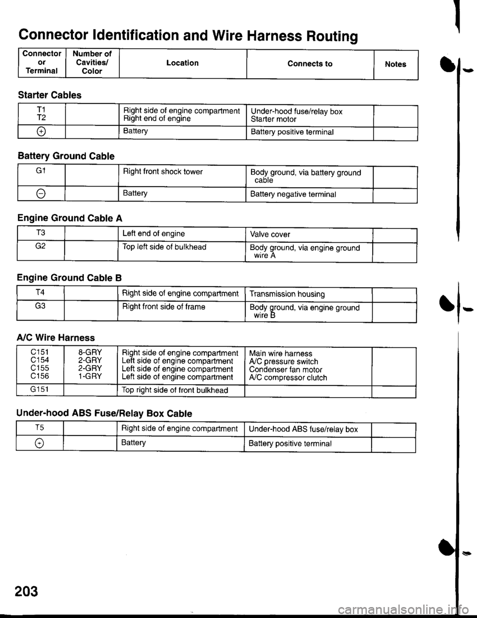
Connector ldentification and Wire Harness Routing
Connector
OT
Terminal
Number of
Cavities/
Color
LocationConnecls toNotesI
fl-
Starter Cables
T1
T2Right side of engine compartmentRight end of engineUnder-hood fuse/relav boxStarter motor
oBatteryBattery positive terminal
Battery Ground Cable
lRight front shock towerBodyground, via battery ground
ABatteryBattery negative terminal
Engine Ground Cable A
T3Left end of engineValve cover
Top left side ol bulkheadBody ground, via engine ground
Engine Ground Cable B
T4Right side of engine compartmentTransmission housing
Right front side of trameBody ground, via engine ground
wrre b
A,/C Wire Harness
Under-hood ABS Fuse/Relay Box Cable
203
c151
c'154utSc
u tco
8-GRY
2-GRY
2-GRY
1-GRY
Right side ol engine compartmentLeft side of engine compartmentLeft srde of engine compartmentLeft side of engine compartment
Main wire harness
A'lC pressure switch
Condenser tan motorA,/C compressor clutch
lrlclTop right side ot front bulkhead
T5Right side of engine compartmentUnderhood ABS fuse/relav box
\,BatteryBattery positive terminal
Page 1598 of 1681
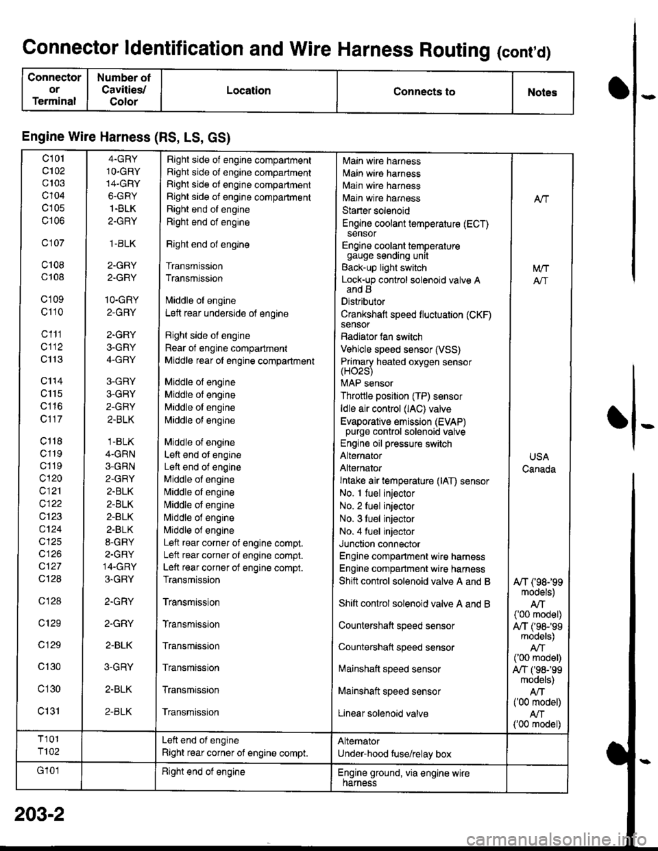
Connector ldentification and Wire Harness Routing (cont,d)
Connector
or
Terminal
Number ot
Cavities/
Color
LocationConnects toNotes
Engine Wire Harness (RS, LS, GS)
c101
c102
c103
c104
c105
c106
c 107
c108
c108
c'1 09
c110
c111
cl12
c113
c'114
c115
c116
c117
c118
c119
c1 19
c120
c121
c122
c123
c124
cl25
cl26
c127
Ql28
c128
c129
c 129
c130
c'l30
c131
4.GRY
1O.GRY
14-GRY
6-GRY
1.BLK
2-GRY
,1-BLK
2-GRY
2.GRY
1O-GRY
2-GRY
2-GRY
3-GRY
4-GRY
3-GRY
3-GRY
2-GRY
2.BLK
.1-BLK
4-GRN
3-GRN
2-GRY
2.BLK
2-BLK
2-BLK
2.BLK
8-GRY
2-GRY
14-GRY
3-GRY
2.GRY
2.GRY
2-BLK
3-GRY
2-BLK
2-BLK
Right side of engine compartment
Right side of engine compartment
Right side ot engine compartment
Right side of engine compartment
Right end of engine
Right end of engine
Right end of engine
Transmission
Transmission
lvliddle ol engine
Lett rear underside of engine
Right side ol engine
Rear of engine compartment
Middle rear ol engine compartment
Middle ol engine
Middle of engine
Middle ol engine
l\4iddle of engine
Middle of engine
Left end ot engine
Lett end of engine
Middle of engine
N,liddle ol engine
Middle of engine
Middle of engine
Middle of engine
Left rear corner of engine compt.
Lelt rear corner of engine compt.
Left rear corner of engine compt.
Transmission
Transmission
Transmission
Transmission
Transmission
Transmission
Transmission
Main wire harness
Main wire harness
Main wire harness
Main wire harness
Starter solenoid
Engine coolant temperature (ECT)sensor
Engine coolant temperaturegauge sending unit
Back-up light switch
Lock-up control solenoid valve Aand B
Distributor
Crankshaft speed fluctuation (CKF)sensor
Radiator fan switch
Vehicle speed sensor (VSS)
Primary heated oxvoen sensor(H02s)
MAP sensor
Throttle position (TP) sensor
ldle air control (lAC) valve
Evaporative emission (EVAP)purge control solenoid valve
Engine oil pressure switch
Alternator
Alternator
Intake air temperature (lAT) sensor
No. I fuel injector
No. 2 fuel injector
No. 3 tuel injector
No. 4 fuel injector
Junction connector
Engine compartment wire harness
Engine compartment wire harness
Shitt control solenoid valve A and B
Shift control solenoid valve A and B
Countershaft speed sensor
Countershatt speed sensor
lvtainshatt speed sensor
Mainshaft speed sensor
Linear solenoid valve
NT
[/VT
A"/T
USA
Canada
A/T (98199models)
AIT('00 model)
A,/T ('98-'�99models)
('00 model)
A,/T f98-'99models)
Atf('00 model)
AN('00 model)
T101
T102
Left end of engine
Right rear corner of engine compt.
Alternator
Under-hood fuse/relay box
G'101Right end ot engineEngine ground, via engine wirenarness
o
I
203-2
Page 1600 of 1681
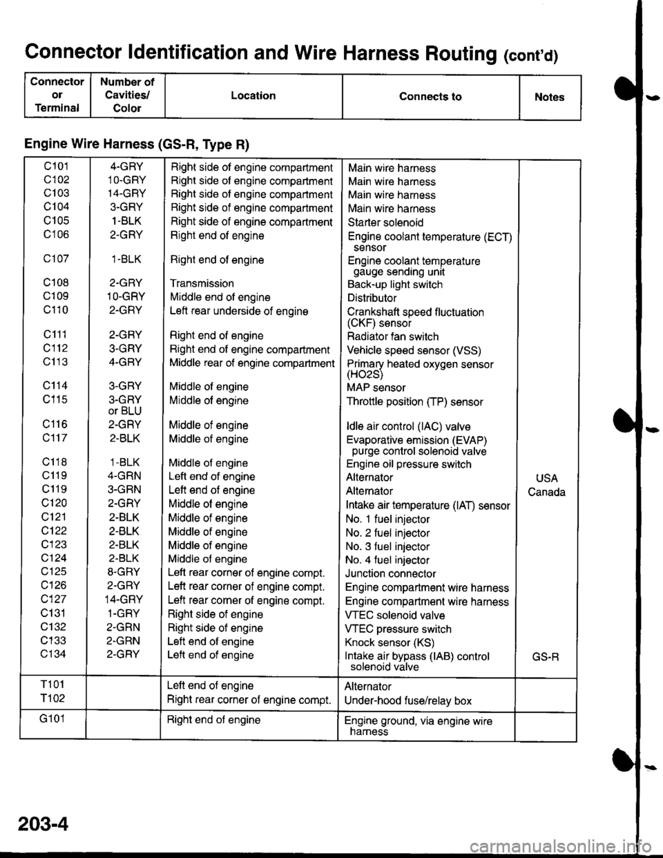
Connector ldentification and Wire Harness Routing (conrd)
Connector
ol
Terminal
Number of
Cavities/
Golor
LocationConnects toNotes
Engine Wire Harness (GS-R, Type R)
c101
c102
c103
c104
U IUC
c106
c107
c108
c109
c110
c111
c112
c113
c114
c115
c116
c117
c118
c11 9
c119
c120
c121
cl22
c123
vtzl
wt10
c127
c131
c132
c133
c134
4-GRY
1O-GRY'I4-GRY
3-GRY
1 -BLK
2-GRY
1.BLK
2-GRY
1O-GRY
2-GRY
2-GRY
3-GRY
4-GRY
3-GRY
3.GRY
or BLU
2-GRY
2-BLK
1 -BLK
4-GRN
3-GRN
2.GRY
2-BLK
2-BLK
2-BLK
2-BLK
8-GRY
2.GRY
14-GRY
1-GRY
2-GRN
2-GRN
2-GRY
Right side of engine compartment
Right side of engine compartment
Bight side of engine compartment
Right side of engine compartment
Right side of engine compartment
Right end of engine
Right end of engine
Transmission
Middle end of engine
Left rear underside of engine
Right end of engine
Right end of engine compartment
Middle rear of engine compartment
Middle of engine
Middle of engine
Middle of engine
Middle of engine
Middle of engine
Left end of engine
Left end of engine
Middle of engine
Middle of engine
Middle of engine
Middle of engine
Middle of engine
Left rear corner of engine compt.
Left rear corner of engine compt.
Left rear corner of engine compt.
Right side of engine
Right side of engine
Left end of engine
Left end of engine
Main wire harness
Main wire harness
Main wire harness
Main wire harness
Starter solenoid
Engine coolant temperature (ECT)
sensor
Engine coolant temperaturegauge sending unit
Back-up light switch
Distributor
Crankshaft speed f luctuation(CKF) sensor
Radiator fan switch
Vehicle speed sensor (VSS)
Primarv heated oxvoen sensor(Hozs)
MAP sensor
Throttle position (TP) sensor
ldle air control (lAC) valve
Evaporative emission (EVAP)purge control solenoid valve
Engine oil pressure switch
Alternator
Alternator
Intake air temperature (lAT) sensor
No. 1 fuel injector
No. 2 fuel injector
No. 3 fuel injector
No. 4 fuel injector
Junction connector
Engine compartment wire harness
Engine compartment wire harness
VTEC solenoid valve
VTEC pressure switch
Knock sensor (KS)
Intake air bypass (lAB) controlsolenoid valve
USA
Canada
GS.R
T101
r102
Left end of engine
Right rear corner of engine compt.
Alternator
Under-hood fuse/relay box
G101Right end of engineEngine ground, via engine wirenarness
203-4
Page 1608 of 1681
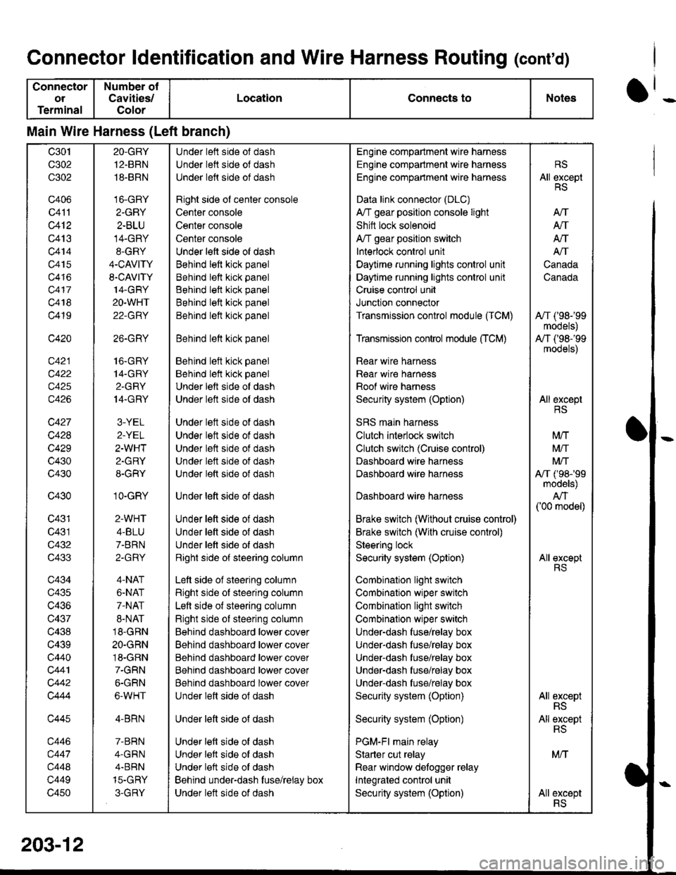
Connector ldentification and Wire Harness Routing (conrd)
Connector
ot
Terminal
Number of
Cavities/
Color
LocationConnects toNotes
Main Wire Harness (Left branch)
c30t
c302
c302
c406
c41'l
c412
c413
c414
c415
c416
c417
c418
c419
c420
c422
c425
c426
c427
c428
c429
c430
c430
c430
c431
c431
c432
c433
c434
c435
c436
c437
c438
c439
c440
c441
c442
Q444
c445
c446
c447
c448
c449
c450
2O-GBY
12.BRN
18-BRN
16-GRY
2-GRY
2-BLU
14-GRY
8-GRY
4-CAVITY
S.CAVITY
14.GRY
2O-WHT
22-GRY
26.GRY
16.GRY
14-GRY
2.GRY
14.GRY
3-YEL
2-YEL
2-WHT
2.GRY
8-GRY
1O-GRY
2-WHT
4-BLU
7-BRN
2-GRY
4-NAT
6-NAT
7-NAT
8-NAT
18-GRN
2O-GRN
18-GRN
7-GRN
6-GRN
6-WHT
4-BRN
7-BRN
4.GRN
4.BBN
15-GHY
3-GRY
Under left side of dash
Under lett side ol dash
Under left side of dash
Right side ol center console
Center console
Center console
Center console
Under left side of dash
Behind left kick panel
Behind lett kick panel
Behind left kick panel
Behind left kick panel
Behind lett kick panel
Behind lett kick panel
Behind left kick panel
Behind lelt kick panel
Under left side of dash
Under left side ot dash
Under lett side of dash
Under lett side of dash
Under left side of dash
Under left side of dash
Under left side of dash
Under lett side of dash
Under left side of dash
Under left side of dash
Under lett side of dash
Right side of steering column
Lett side of steering column
Right side of steering column
Left side of steering column
Right side of steering column
Behind dashboard lower cover
Behind dashboard lower cover
Behind dashboard lower cover
Behind dashboard lower cover
Behind dashboard lower cover
Under left side of dash
Under left side of dash
Under left side of dash
Under left side of dash
Under left side of dash
Behind under-dash fuse/relay box
Under lett side of dash
Engine compartment wire harness
Engine compartment wire harness
Engine comparlmenl wire harness
Data link connector (DLC)
A/T gear position console light
Shitt lock solenoid
A/T gear position switch
Interlock control unit
Daytime running lights control unit
Daytime runnang lights control unit
Cruise control unit
Junction connector
Transmission control module (TCM)
Transmission control module CrCM)
Rear wire harness
Rear wir€ harn€ss
Roof wire harness
Security system (Option)
SRS main harness
Clutch interlock switch
Clutch switch (Cruise control)
Dashboard wire harness
Dashboard wire harness
Dashboard wire harness
Brake switch (Without cruise control)
Brake switch (With cruise control)
Steering lock
Security system (Option)
Combination light switch
Combination wiper switch
Combination light switch
Combinalion wiper switch
Under-dash fuse/relay box
Under-dash fuse/rglay box
Under-dash fuse/relay box
Under-dash fuse/relay box
Under-dash fuse/relay box
Security system (Option)
Security system (Option)
PGM-Fl main relay
Starter cut relay
Rear window detogger relay
Integrated control unit
Security system (Option)
RS
All exceptRS
AtT
Atf
AN
A/T
Canada
Canada
A,/T ('98-'99
models)
A,/T (,98-'99
models)
All exceptRS
M/T
Mtf
Mrf
A,/T ('98-'99models)
AN('00 model)
All exceptRS
All exceptRS
All exceptRS
MN
AII excsptRS
203-1
Page 1632 of 1681
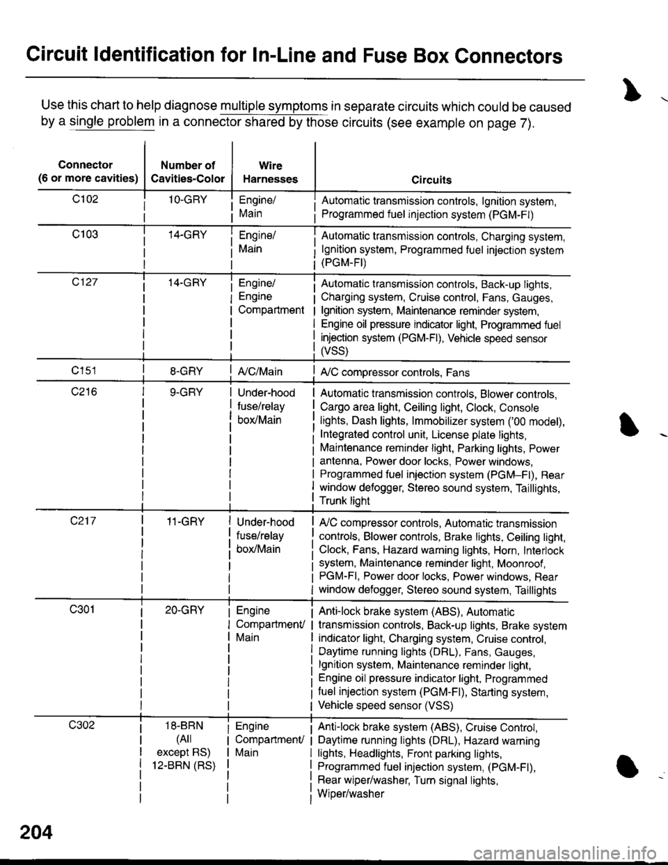
Circuit ldentification for In-Line and Fuse Box Connectors
Use this chart to help diagnose multiple symptoms in separate circuits which could be caused
by a single problem in a connector shared by those circuits (see example on page 7).
Connector
(6 or more cavities)
Number of
Cavities-Color
Wire
Harnesses
Engine/
Main
Engine/
Engine
Compartment
I Automatic transmission controls, lgnition system,
i Programmed fuel injection system (PGM-F|)
Automatic transmission controls, Charging system,
lgnition system, Programmed fuel injection system(PGM-FI)
Automatic transmission controls, Back-up lights,
Charging system, Cruise control, Fans, Gauges,
lgnition system, Maintenance reminder system,
Engine oil pressure indicator light, Programmed fuel
injection system (PGM-Fl), Vehicle speed sensor
ffss)
| {c/Main! A,/C compressor controls, Fans
Under-hood
fuse/relay
box/Main
Automatic transmission controls, Blower controls,
Cargo area light, Ceiling light, Clock, Console
lights, Dash lights, lmmobilizer system ('00 model),
Integrated control unit, License plate lights,
Maintenance reminder light, Parking lights, Power
antenna, Power door locks, Power windows,
Programmed fuel iniection system (PGM-Fl), Rear
window defogger, Stereo sound system, Taillights,
Trunk lioht
11-GRY
18-BBN
(4il
except BS)
12-BBN (RS)
Under-hood
fuse/relay
box/Main
Engine
CompartmenV
Main
Engine
CompartmenU
Main
lr,/C compressor controls, Automatic transmission
controls, Blower controls, Brake lights, Ceiling light,
Clock, Fans, Hazard warning lights, Horn, Interlock
system, Maintenance reminder light, Moonroof ,PGM-FI, Power door locks, Power windows, Rear
window defogger, Stereo sound system, Taillights
Anti-lock brake system (ABS), Automatic
transmission controls, Back-up lights, Brake system
indicator light, Charging system, Cruise control,
Daytime running lights (DRL), Fans, Gauges,
lgnition system, Maintenance reminder light,
Engine oil pressure indicator light, Programmed
tuel injection system (PGM-F|), Starting system,
Vehicle speed sensor (VSS)
Anti-lock brake system (ABS), Cruise Conkol,
Daytime running lights (DRL), Hazard warning
lights, Headlights, Front parking lights,
Programmed fuel injection system, (PGM-Fl),
Rear wiper/washer, Turn signal lights,
Wiper/washer
204
Page 1633 of 1681
)ot
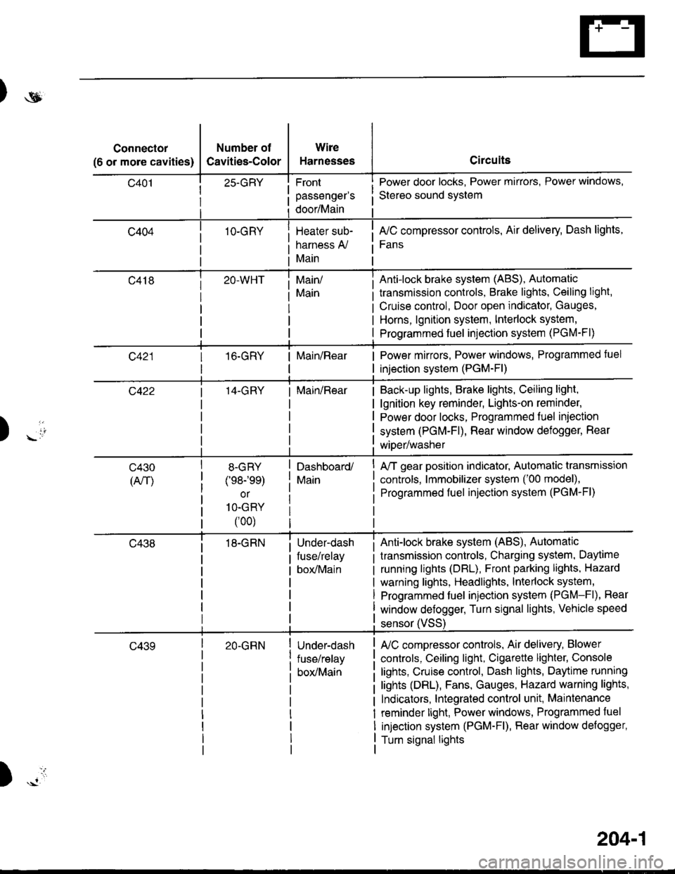
Connector
(6 or more cavities)
Number of
Cavities-Color
25-GRY
1O-GRY
Wire
Harnesses
Front
passenger's
door/Main
Heater sub-
harness A,/
Main
Circuits
Power door locks, Power mirrors, Power windows,
Stereo sound svstem
fuC compressor controls, Air delivery, Dash lights,
Fans
transmission controls, Brake lights, Ceiling light,
Cruise control, Door open indicator, Gauges,
Horns, lgnition system, Interlock system,
Programmed fuel injection system (PGM-Fl)
Main/
Main
Anti-lock brake system (ABS), Automatic
16.GRYMain/RearPower mirrors, Power windows, Programmed tuel
injection system (PGM-Fl)
14-GRYMain/RearBack-up lights, Brake lights, Ceiling light,
lgnition key reminder, Lights-on reminder,
Power door locks, Programmed fuel iniection
system (PGM-Fl), Rear window defogger, Rear
wiDer/washer) -io
tl
c430
(An)
8-GRY
(e8-'ee)
or
1O-GRY
(00)
18-GRN
Dashboard/
Main
Under-dash
fuse/relay
box/Main
A/T gear position indicator, Automatic transmission
controls, lmmobilizer system ('00 model),
Programmed fuel injection system (PGM-Fl)
Anti-lock brake system (ABS), Automatic
transmission controls, Charging system, Daytime
running lights (DBL), Front parking lights, Hazard
warning lights, Headlights, lnterlock system,
Programmed fuel injection system (PGM-Fl), Rear
window defogger, Turn signal lights, Vehicle speed
c43920-GRNUnder-dash
fuse/relay
box/Main
sensor (VSS
L/C compressor controls, Air delivery, Blower
controls, Ceiling light, Cigarette lighter, Console
lights, Cruise control, Dash lights, Daytime running
lights (DRL), Fans, Gauges, Hazard warning lights,
Indicators, lntegrated control unit, Maintenance
reminder light, Power windows, Programmed fuel
injection system (PGM-Fl), Rear window defogger,
Turn signal lights
)
204-1
Page 1638 of 1681
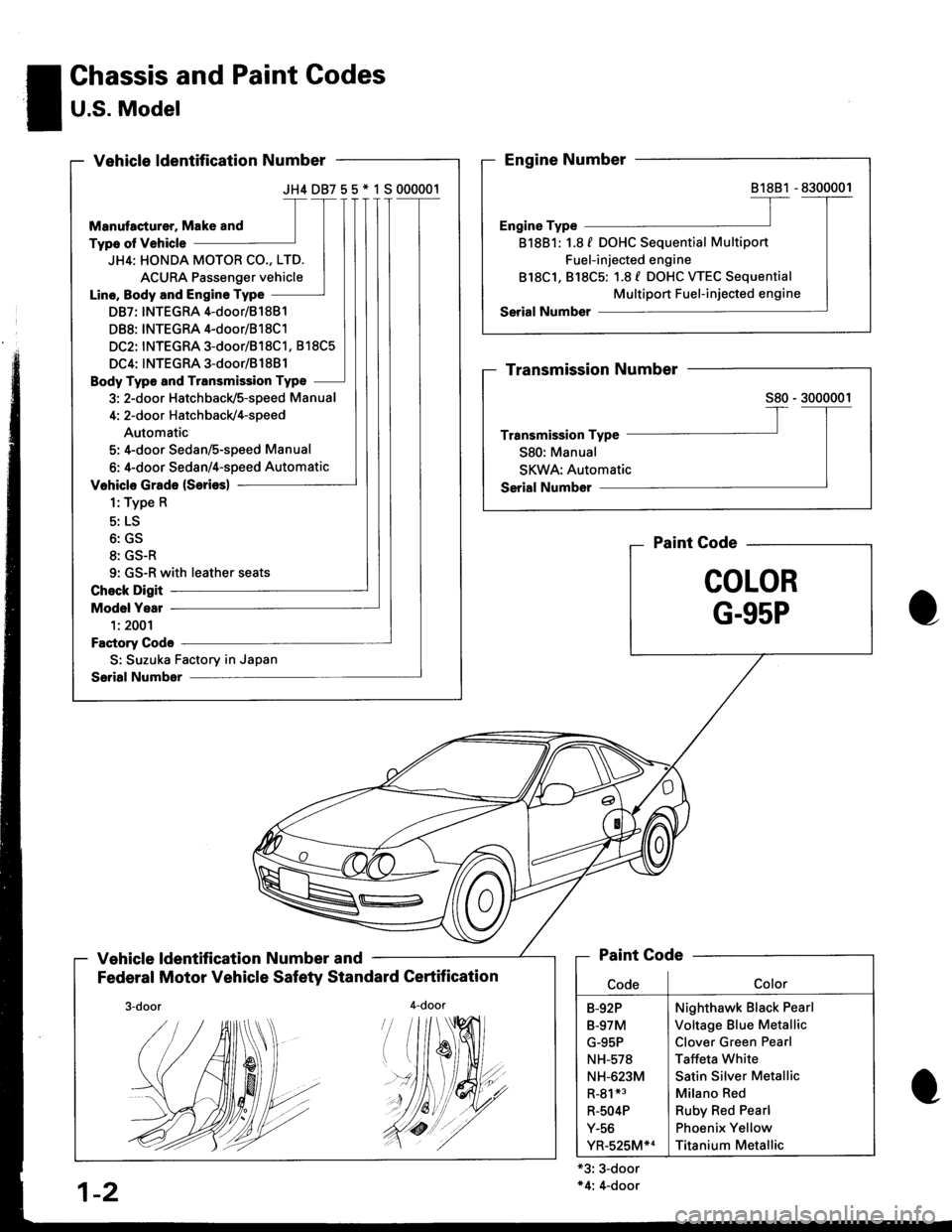
JH4DB755*1S000001
JH4: HONDA MOTOR CO., LTD.
ACURA Passenger vehicle
Line, Body and Engine Type
DB7: INTEGRA 4-door/81 881
DB8: INTEGRA 4-door/B1 8C1
DC2: INTEGRA 3-door/818C1, 818C5
DC4: INTEGRA 3-door/B1881
Body Type and Transmission Type
3: 2-door Hatchback/5-speed Manual
4: 2-door Hatch back/4-speed
Automatic
5: 4-door Sedan/S-speed Manual
6: 4-door Sedan/4-speed Automatic
9: GS-R with leather seats
S: Suzuka Factory in Japan
! Chassis and Paint Codes
I U.S. Model-
Vehicle ldentification Number and
Federal Motor Vehicle Safety Standard Certification
4-door
Paint Gode
COLOR
G-95P
'#19
'//dt
+3: 3-door*4: 4-door
81881
818B1: 1.8 f DOHC Sequential Multiport
Fuel-injected engine
818C1, 818C5: 1.8 f DOHC WEC Sequential
Multiport Fuel-injected engine
Paint Code
Nighthawk Black Pearl
Voltage Blue Metallic
Clover Green Pearl
Taffeta White
Satin Silver Metallic
Milano Red
Ruby Red Pearl
Phoenix Yellow
Titanium Metallic
B-92P
B-97M
G-95P
NH-578
NH-623M
R-81*3
R-504P
Y-56
YR-525M*4
1-2
./.4r//.'.
Page 1639 of 1681
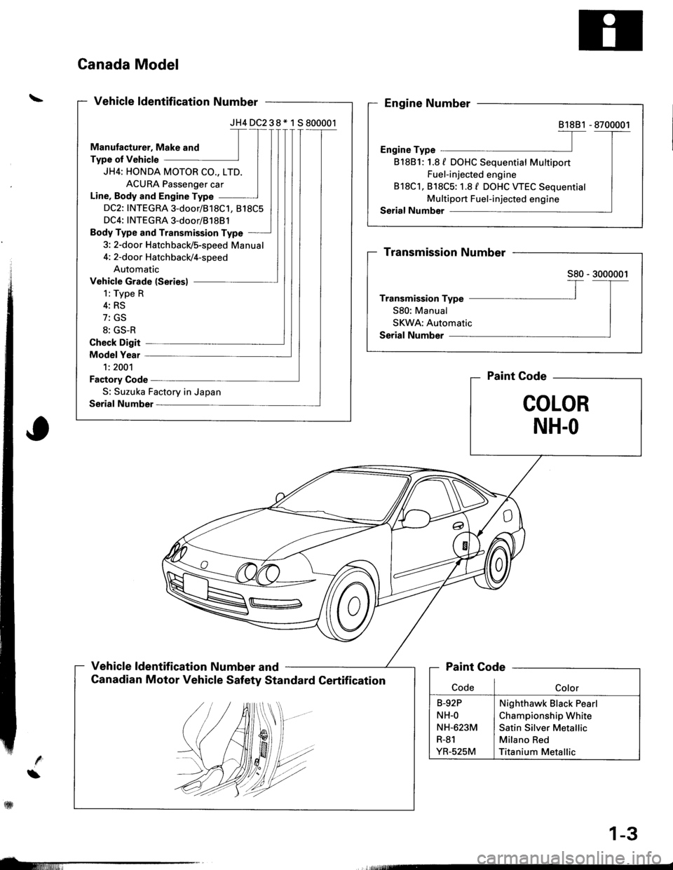
JH4DC238* 1 S800001
JH4: HONDA MOTOR CO., LTD.
ACURA Passenger car
Line, Body and Engine Type
DC2: INTEGRA 3-door/818C1, 818C5
DC4: INTEGRA 3-door/81 88l
Body Type and Transmission Type
3: 2-door Hatchbacld5-speed Manual
S: Suzuka Factory in Japan
\
Canada Model
Vehicle ldentification Number and
Canadian Motor Vehicle Safety Standard Gertification
Paint Gode
COLOR
NH.O
81881
818B1: 1.8 f DOHC Sequential Multiport
Fuel-injected engine
818C1, 818C5: 1.8 / DOHC WEC Sequential
Multiport Fuel-injected engine
Nighthawk Black Pearl
Championship White
Satin Silver Metallic
Milano Red
Titanium Metallic
rfilill
1-3