check engine HONDA INTEGRA 1998 4.G Workshop Manual
[x] Cancel search | Manufacturer: HONDA, Model Year: 1998, Model line: INTEGRA, Model: HONDA INTEGRA 1998 4.GPages: 1681, PDF Size: 54.22 MB
Page 585 of 1681
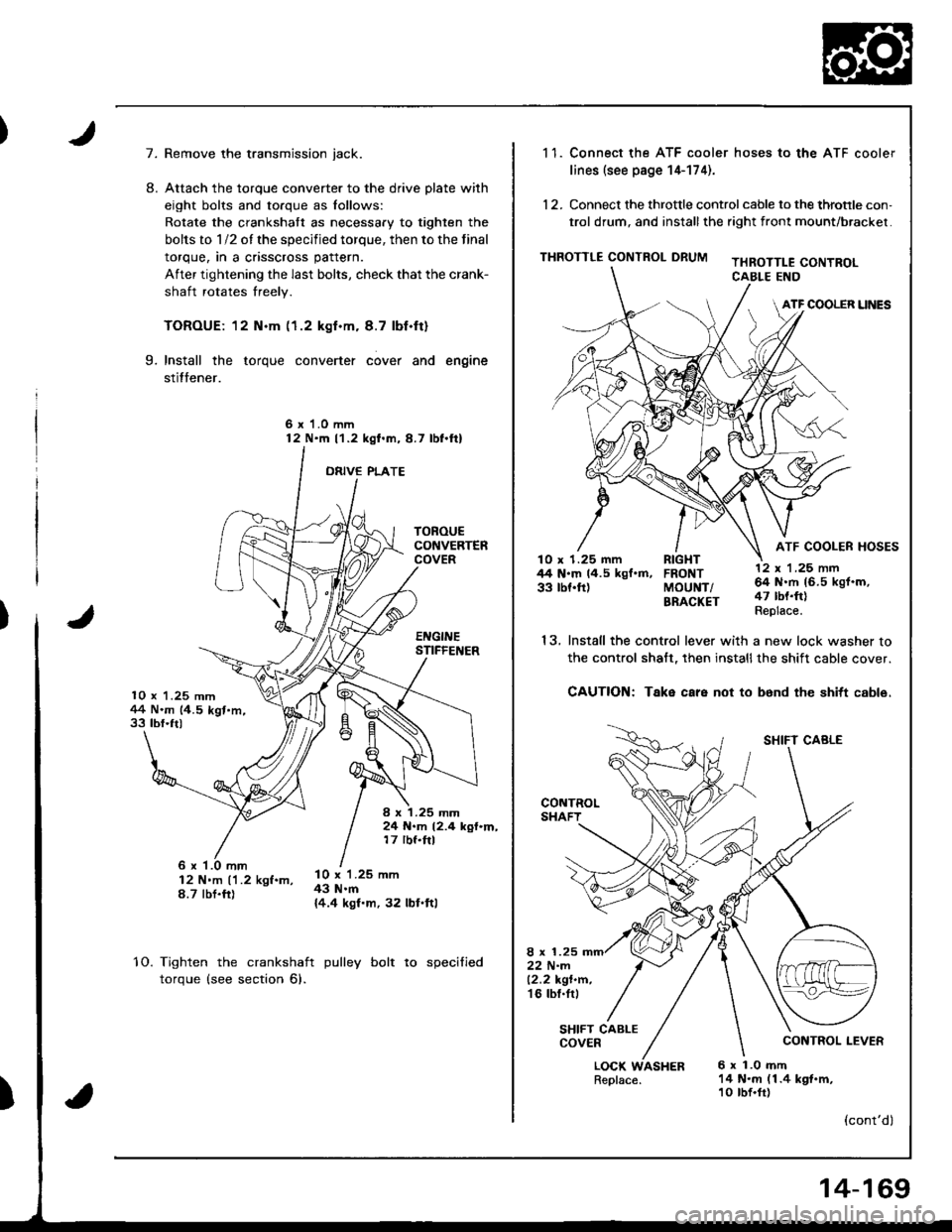
7.
10 x 1.25 mm1+4 N.m (4.5 kgt.m,33 tbf.ft)
TOROUECONVERTERCOVER
EI{GINESTIFFEI{ER
I x 1.25 mm24 N.m 12.4 kgf.m,17 rbf.ftl
8.
Remove the transmission jack.
Attach the torque converter to the drive plate with
eight bolts and torque as lollows:
Rotate the crankshatt as necessary to tighten the
bolts to 1/2 of the specified torque, then to the final
torque, in a crisscross pattern.
After tightening the last bolts, check that the crank-
shaft rotates freely.
TOROUE: 12 N.m (1.2 kgf.m. 8.7 lbf.ft)
Install the torque converter cover and engine
stitfener.
6 x 1.0 mm12 N'm l'1.2 kgl.m,8.7 lbl.ftl
ORIVE PLATE
9.
6 x '1.0 mm12 N'm ('1.2 kgf.m,8.7 tbt.fr)
l0 x 1.25 mm43 N.m{4.4 kgf.m, 32 lbl.ftl
10.Tighten the crankshaft
torque (see section 6).
pulley bolt to specified
)
1 1. Connect the ATF cooler hoses to the ATF cooler
lines (see page 14-174).
12. Connect the throttle control cable to the throtrle con,
trol drum, and installthe right front mount/brackel.
THROTTLE CONTROL DRUMTHROTTLE CONTROLCABLE END
ATF COOLER UNES
ATF COOLER HOSESlO x 1.25 mm RIGHT44 N.m 14.5 kgf.m, FRONT33 tbf.ft) MoUNT/BRACKET
13.
LOCK WASHERReplace.6 x 1.0 mft14 N.m (1.4 kgt.m,10 tbf.fr)
12 x 'l ,25 nn64 N.rh 16.5 kgf.m,47 tbt.ft)Replace.
SHIFT CABLE
CONTROL LEVER
(cont'dl
Install the control lever with a new lock washer to
the control shalt, then installthe shift cable cover.
CAUTION: Take care not to b6nd the shitt cable.
8 x 1.2522 N-m12.2 kgt.n.'t6 tbl.tr,
SHIFT CABLECOVER
14-169
Page 587 of 1681
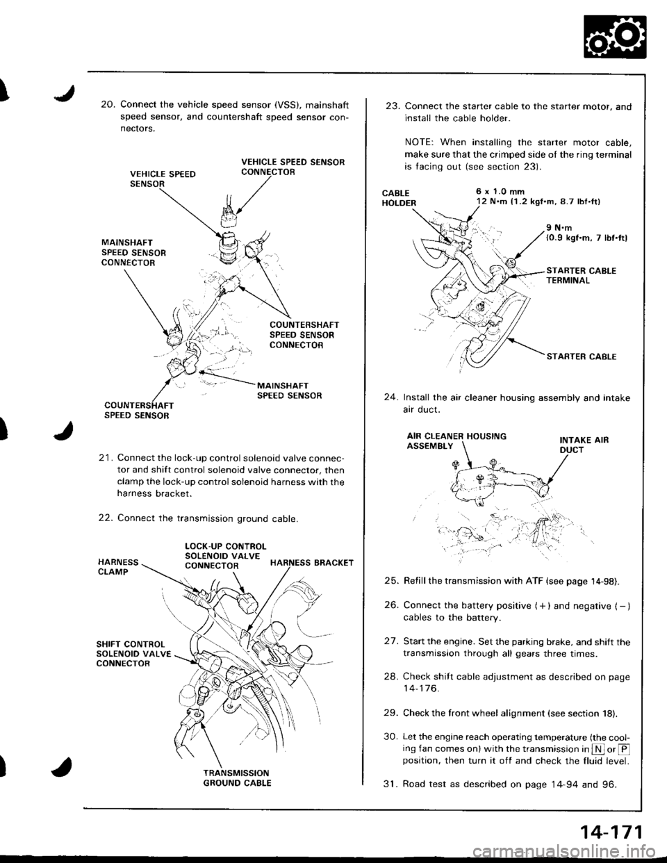
I20.Connect the vehicle speed sensor (VSS), mainshaft
speed sensor, and countershaft sDeed sensor con-
nectors.
VEHICLE SPEED SENSORCONNECTOB
)
k/
t"J
21. Connect the lock-up control solenoid valve connec-
tor and shift control solenoid valve conneclor, then
clamp the lock-up control solenoid harness with the
harness bracket.
22. Connect the transmission ground cable.
SPEED SENSOR
LOCK-UP CONTROLSOLENOID VALVECONNECTOR
23.Connect the starter cable to the starter motor, and
install the cable holder.
NOTE: When installing the starter motor cable,
make sure that the crimped side ol the ring terminal
is facing out (see section 23).
6 x 1.0 mm12 N.m {1 .2 kgf.m, 8.7 lbl.ft)
9 N.m(0.9 kgf.m, 7 lbt.ttl
STARTER CABLETERMINAL
STARTER CABLE
24.Install the air cleaner housing assembly and intake
arr oucl.
AIR CLEANER HOUSINGINTAKE AIRASSEMBLY
27.
Refill the transmission with ATF {see page 14-98).
Connect the battery positive (+ ) and negative { - }cables to the battery.
Start the engine. Set the parking brake, and shift the
transmission through all gears three times.
Check shilt cable adjustment as described on page
14-176.
Check the front wheel alignment (see section 18).
Let the engine reach operating temperature (the cool-ing fan comes onl with the transmission in S or @position, then turn it off and check the fluid level.
31. Road test as described on page 14-94 and 96.
25.
26.
24.
29.
30.
14-171
Page 592 of 1681
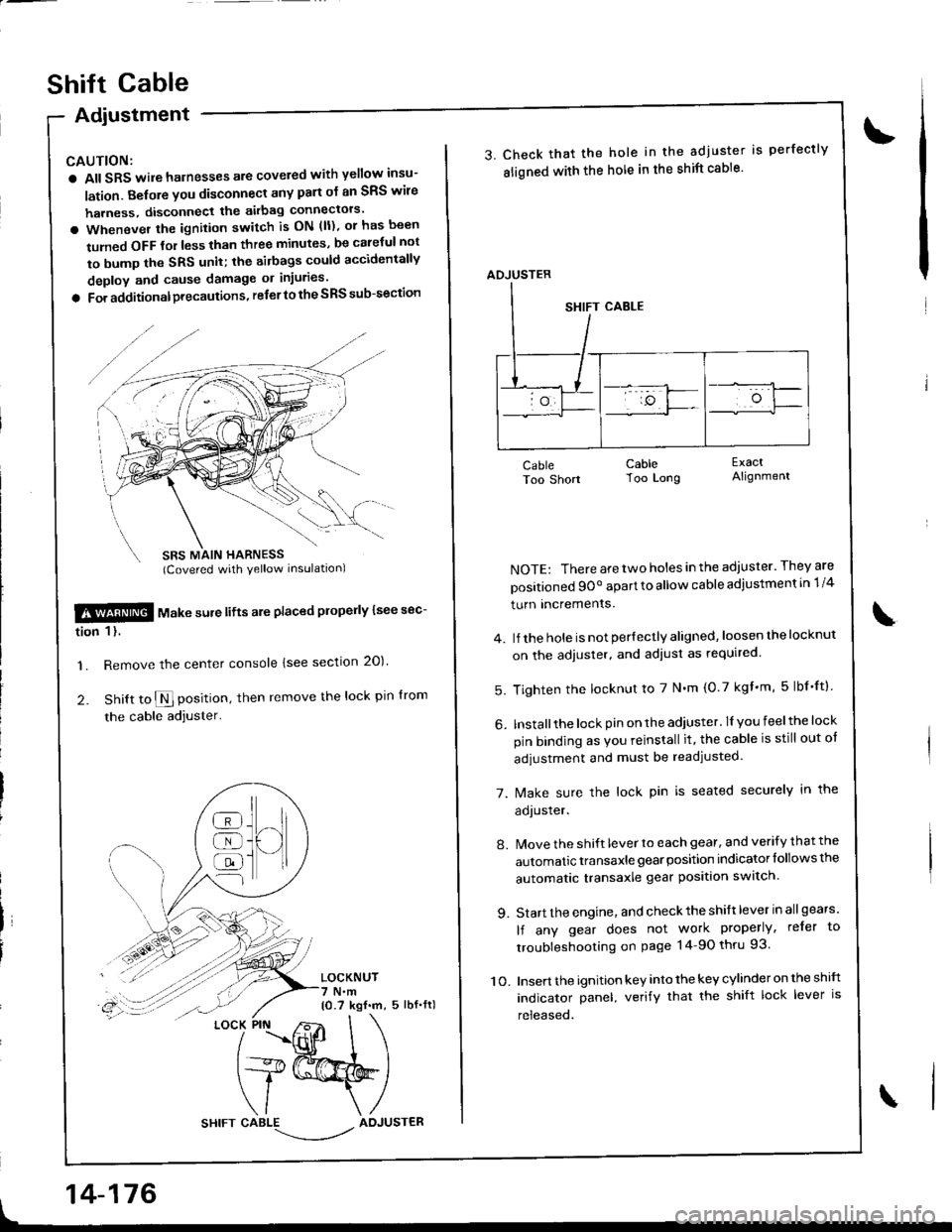
Adiustment
CAUTION:
a All SRS wile harnesses are covered with yellow insu-
lation. Belore you disconnect any part ol an SRS wire
harness, disconnect the akbag connectors'
a Whenever the ignition switch is ON (ll), or has been
tumed OFF tol less than three minutes, be caletul not
to bump the SRS unit; the airbags could accidentally
deploy and cause damage or injuries'
a For additionalprecautions, referto the SRS sub-section
SBS MAIN HARNESS(Covered with yellow inslrlationl
$!@ rtl"t . "ure lifts are placed plope y lsee sec-
tion 1 l.
'1. Remove the center console lsee section 20)'
2. Snitt to $ position, then remove the lock pin lrom
the cable adjuster'
LOCKNUT7 N.m10.7 kgf.m, 5 lbf.fl)
t
]H
@
@
@
{l
LOCK PIN
14-176
shift cable
3. Check that the hole in the adjuster is perfectly
sligned with the hole in the shift cable'
CableToo Short
NOTE: There are two holes in the adjuster. They are
positioned 9Oo apart to allow cable adiustment in 1/4
turn Incremenrs.
4. lJ the hole is not per{ectly aligned, loosen the locknut
on the adjuster, and adiust as required.
5. Tighten the locknut to 7 N'm (0.7 kgf'm, 5lbf'ftl
6. Installthe lock pin on the adiuster. lI you feelthe lock
pin binding as Vou reinstall it, the cable is still out ot
adjustment and must be readjusted.
7. [/ake sure the lock pin is seated securely in the
aoJusrer.
8. Move the shift lever to each gear, and verify that the
automatic transaxle gear position indicator follows the
automatic transaxle gear position swatch.
9. Start the engine, and check the shift lever in allgears'
lf any gear does not work properly, refer to
troubleshooting on page 14-90 thru 93.
10. Insert the ignition key into the key cylinder on the shift
indicator panel, verify that the shift lock lever is
released.
CableToo Long
ExactAlignment
\
ADJUSTER
Page 612 of 1681
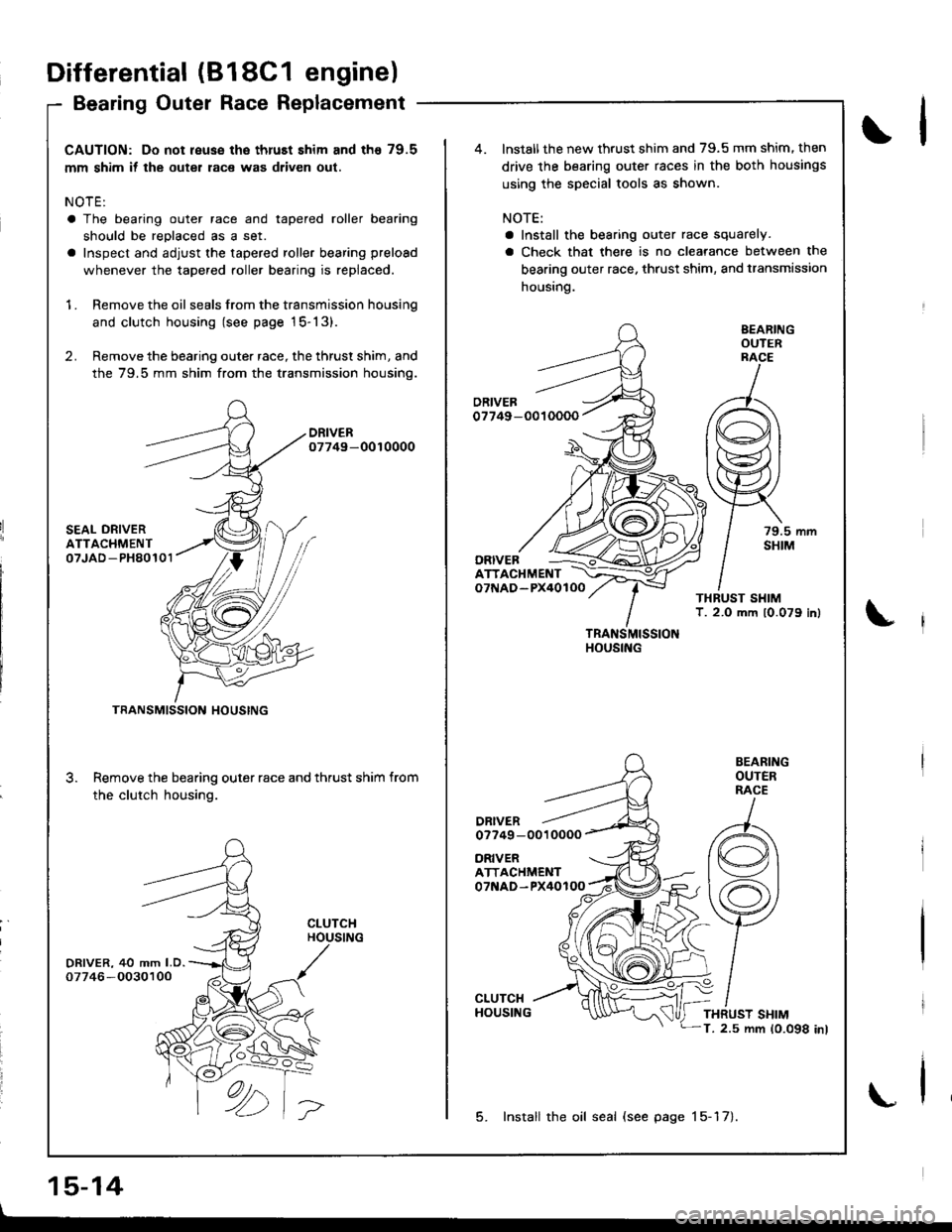
CAUTION: Do not reuse the thruEt shim and th€ 79.5
mm shim if the outer race was driven out.
NOTE:
a The bearing outer race and tapered roller bearing
should be reDlaced as a set.
a Inspect and adjust the tapered roller bearing preload
whenever the tapered roller bearing is replaced.
1 . Remove the oil seals from the transmission housing
and clutch housing (see page 15-13).
2. Remove the bearing outer race, the thrust shim, and
the 79.5 mm shim from the transmission housino.
DRIVER07749-0010000
SEAL ORIVERATTACHMENT07JAD -PH80101
DRIVER, 40 mm LD.07746 -O030100
3.
TRANSMISSION HOUSING
Remove the bearing outer race and thrust shim from
the clutch housing.
CLUTCHHOUSING
ORIVERATTACHMENT07NAD-PX40100
ATTACHMENTo7f{AD-PX40lOO
DRIVERo7749 -0010000
TRANSMISSIONHOUSING
BEARINGOUTERRACE
79.5 mmSHIM
BEARINGOUTERRACE
THRUST SHIMT. 2.5 mm 10.098 inl
lnstall the new thrust shim and 79.5 mm shim. then
drive the bearing outer races in the both housings
using the special tools as shown.
NOTE:
a Install the bearing outer race squarely.
a Check that there is no clearance between the
bearing outer race. thrust shim, and transmission
housing.
ORIVEB
5. Install the oil seal (see page 15-17).
Differential (818C1 engine)
Bearing Outer Race Replacement
15-14
\l
\
\
Page 614 of 1681
Differential
Ted Roll
(B18C1
er Bearinr
engine)
Preload Adjustment (cont'd)aperelng
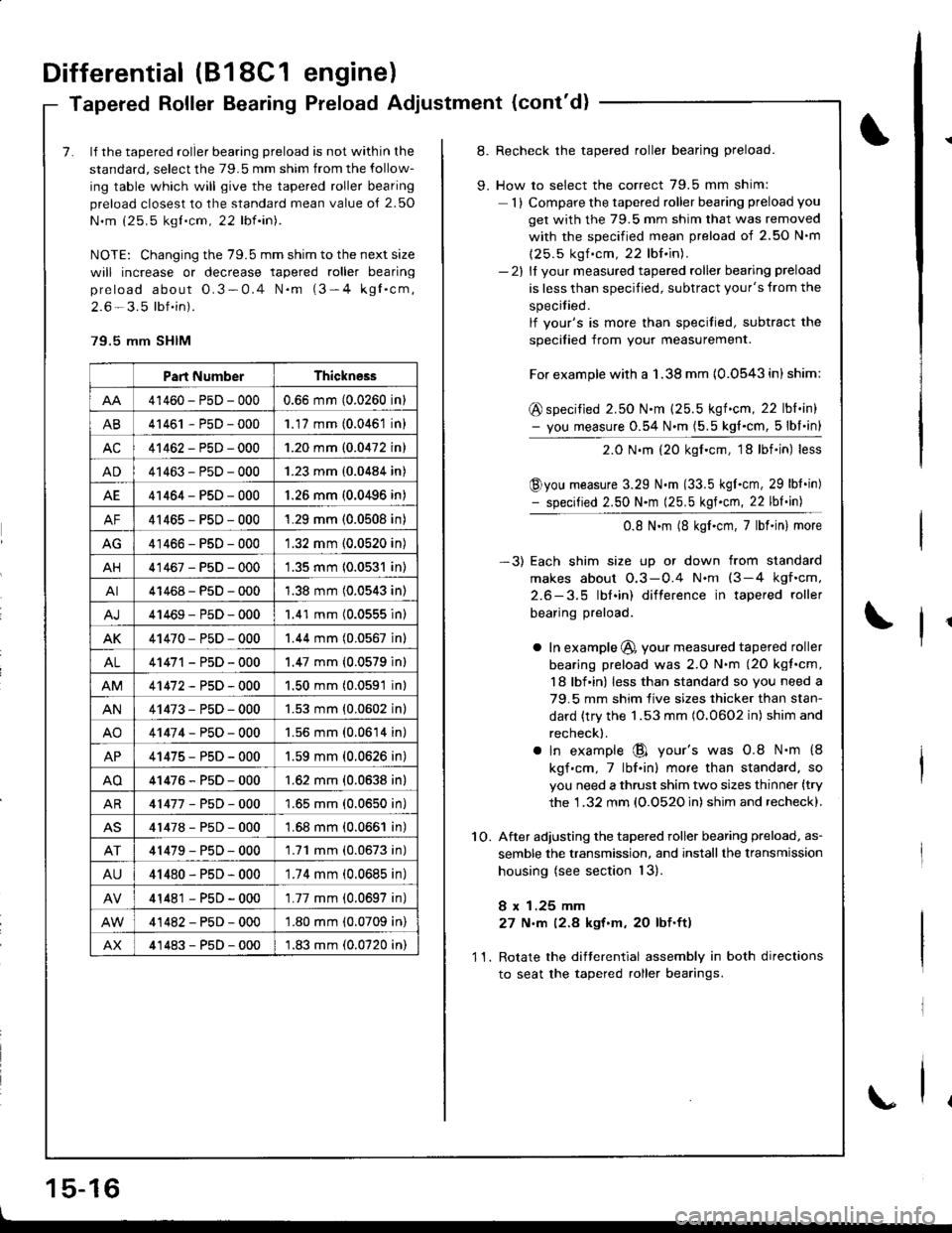
7. lf the tapered roller bearing preload is not within the
standard, select the 79.5 mm shim from the follow-
ing table which will give the tapered roller bearing
preload closest to the standard mean value o{ 2.50
N.m (25.5 kgt.cm, 22 lbf.in).
NOTE: Changing the 79.5 mm shim to the next size
will increase or decrease tapered roller bearing
preload about O.3-0.4 N.m (3-4 kgl.cm,
2.6 - 3.5 lbf.in).
79.5 mm SHIM
Part NumberThickness
41460-PsD-0000.66 mm (0.0260 in)
AB41461 - P5D - 0001.17 mm (0.0461 in)
AC41462-PsD-0001.20 mm (0.0472 in)
AD41463-P5D-0001.23 mm (0.0484 in)
AE41464-PsD-000'1.26 mm (0.0496 in)
AF41465-PsD-0001.29 mm (0.0508 in)
AG41466-PsD-0001.32 mm (0.0520 in)
AH41467-PsD-0001.35 mm 10.0531 in)
AI41468-PsD-0001.38 mm (0.0543 in)
41469-P5D-0001.41 mm (0.0555 inl
AK41470-PsD-0001.44 mm (0.0567 in)
AL41471 - PsD - 000'1.47 mm {0.0579 in}
41472-P5D-0001.50 mm (0.0591 in)
AN41473-PsD-0001.53 mm {0.0602 in}
AO41474-P50-0001.56 mm (0.0614 in)
AP41475-PsD-0001.59 mm (0.0626 in)
AO41476-P5D-000'1.62 mm {0.0638 in}
AR41477-P5D-0001.65 mm (0.0650 in)
41478-P5D-0001.68 mm (0.0661 in)
41479-P50-0001.71 mm (0.0673 in)
AU41480-PsD-0001.74 mm (0.0685 in)
41481 - PsD - 000'1.77 mm (0.0697 in)
41482-PsD-000'1.80 mm (0.0709 in)
AX41483-P5D-0001.83 mm (0.0720 in)
8. Recheck the tapered roller bearing preload.
9. How to select the correct 79.5 mm shim:
1) Compare the tapered roller bearing preload you
get with the 79.5 mm shim that was removed
with the soecified mean Dreload of 2.50 N'm
(25.5 kgf .cm, 22 lbf.in).- 2l ll vour measured tapered roller bearing preload
is less than specified, subtract your's from the
specitied.
lf vour's is more than specitied, subtract the
soecified from vour measurement.
For example with a 1.38 mm {0.0543 in) shim:
@ specified 2.50 N.m (25.5 kgf.cm, 22 lbl.in)- you measure 0.54 N.m (5.5 kg{.cm, 5lbl.in}
2.0 N.m (20 kgf.cm, 18lbf.in) less
@you measure 3.29 N.m (33.5 kgI.cm, 29 lbt.in)- specified 2.50 N.m (25.5 kgf.cm, 22 lbf.in)
0.8 N.m (8 kgf.cm,7lbf.in) more
-3) Each shim size up or down from standard
makes about O.3-0.4 N.nt (3-4 kgf.cm,
2.6-3.5 lbl.in) difterence in tapered roller
bearing preload.
a In example @, your measured tapered roller
bearing preload was 2.O N.m (2O kgt.cm,
18 lbf in) less than standard so you need a
79.5 mm shim live sizes thicker than stan-
dard {try the 1.53 mm (O.0602 in) shim and
recheck).
a ln example @ your's was 0.8 N.m {8
kgf.cm,7lbf.in) more than standard. so
you need a thrust shim two sizes thinner (try
the 1 .32 mm (O.O52O in) shim and recheck).
1O. After adjusting the tapered roller bearing preload, as-
semble the transmission, and installthe lransmission
housing (see section 13).
8 x 1.25 mm
27 N,m (2.8 kgt'm, 20 lbf.ft)
11. Rotate the difterential assembly in both directions
to seat the tapered roller bearings.
1 5-16
\
Page 620 of 1681
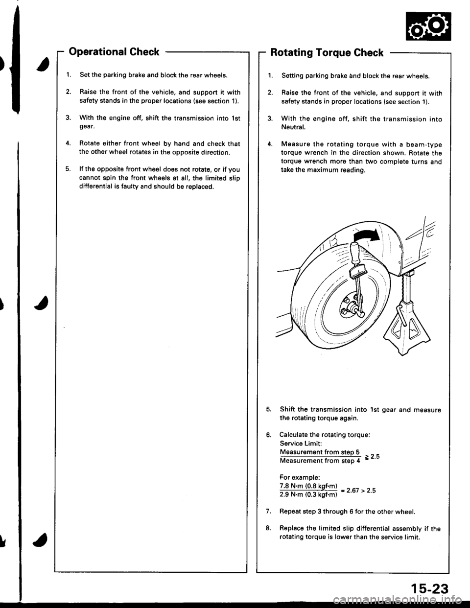
Operational Check
Set the parking brake and block the rear wheels.
Raise the front of the vehicle, and support it with
safety stands in the proper locations (see section 1).
With the engine off, shift the transmission into lstgear,
Rotate either front wheel bv hand and check that
the other wheel rotates in the opposite direction.
lf the opposite tront wheel does not rotste, or if voucannot spin the front wheels at all, the limited slip
differential is faulty and should be roplaced.
Rotating Torque Check
Setting parking brake and block the rear wheels.
Raise the front of the vehicle, and support it with
safety stands in proper locations (see section 1).
With the engine off, shift the transmission into
Neutral.
Measure the rotating torque with a beam-type
torquo wrench in the direction shown, Rotate the
torque wrench morg than two complete turns and
take the maximum reading.
Shift the transmission into 1st gear and measure
the rotating torque again.
Calculate the rotating torque:
Service Limit:
Measur€ment from steD 5
Measurementfrom step 4 =--
For example:
7.8 N.m (0.8 kgf.m)
zg N"ll (03 kgf'ntl = z'ot > z''
Repeat step 3 through 6 for the other wheel.
Replace the limited slip differential assembly if the
rotsting lorque is lower than the service limit.
!
15-23
Page 623 of 1681
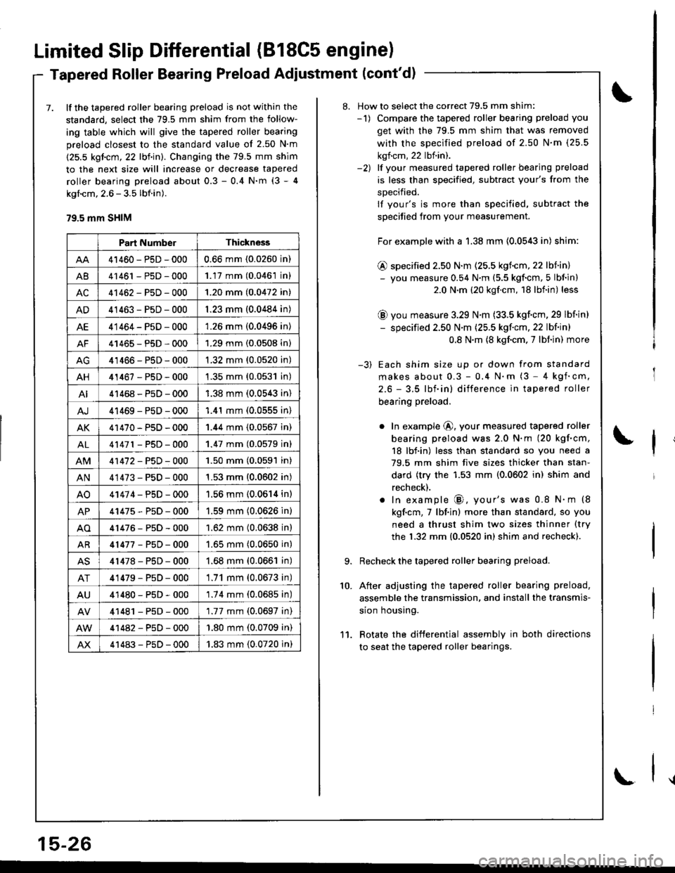
Limited Slip Differential (B18C5 engine)
Tapered Roller Bearing Preload Adiustment (cont'd)
7. lf the tapered roller bearing preload is not within the
standard, select the 79.5 mm shim from the follow-
ing table which will give the tapered roller bearing
preload closest to the standard value of 2.50 N'm
(25.5 kgicm, 22 lbf in). Changing the 79.5 mm shim
to the next size will increase or decrease tapered
roller bearing preload about 0.3 - 0.4 N'm (3 - 4
kgl.cm, 2.6 - 3.5 lbf.in).
79.5 mm SHIM
Part NumberThickness
41460-PsD-0000.66 mm (0.0260 in)
A841461 - P5D - 0001.17 mm (0.0461 in)
AC41462-P5D-0001.20 mm (0.0472 in)
AD41463-P5D-0001.23 mm (0.0484 in)
AE41464-P5D-0001.26 mm (0.0496 in)
AF41465-P5D-0001.29 mm (0.0508 in)
41466-PsD-0001.32 mm (0.0520 in)
AH41467-PsD-0001.35 mm (0.0531 in)
AI41468-P5D-0001.38 mm (0.0543 in)
AJ41469-PsD-0001.41 mm (0.0555 in)
AK41470-PsD-0001.44 mm (0.0567 in)
AL41471 - PsD - 0001.47 mm (0.0579 inl
41472-P5D-0001.50 mm (0.0591 in)
AN41473-P5D-0001.53 mm (0.0602 in)
AO41474-PsD-0001.56 mm (0.0614 in)
AP41475-P5D-0001.59 mm (0.0626 in)
AO41476-P5D-0001.62 mm (0.0638 in)
AR41477-P5D-0001.65 mm (0.0650 in)
AS41478-PsD-0001.68 mm (0.0661 in)
AT41479-P5D-0001.71 mm (0.0673 in)
AU41480-PsD-0001.74 mm (0.0685 in)
41481 - PsD - 0001.77 mm (0.0697 in)
41482-P5D-000'1.80 mm (0.0709 in)
AX41483-P5D-0001.83 mm (0.0720 in)
15-26
\
8. How to select the correct 79,5 mm shim:-1) Compare the tapered roller bearing preload you
get with the 79.5 mm shim that was removed
with the sDecified preload of 2.50 N'm (25.5
kgf.cm, 22 lbf.in).-2) lf vour measured tapered roller bearing preload
is less than specified, subtract your's from the
sDecified.
lf your's is more than specified, subtract the
specified from your measurement.
For example with a 1.38 mm (0.0543 in) shim:
@ specified 2.50 N.m (25.5 kgf.cm,22 lbiin)- you measure 0.54 N.m (5.5 kgf'cm, 5 lbf in)
2.0 N.m (20 kgf.cm, 18 lbf.in) less
@ you measure 3.29 N.m (33.5 kgf.cm, 29 lbf in)
- specified 2.50 N'm (25.5 kgf'cm, 22 lbf in)
0.8 N.m {8 kgf.cm. 7 lbf in) more
-3) Each shim size up or down from standard
makes about 0.3 - 0,4 N.m (3 - 4 kgf'cm,
2.6 - 3.5 lbf.in) difference in tapered roller
bearing preload.
o In example @, your measured tapered roller
bearing preload was 2.0 N.m (20 kgf.cm,
18 lbf.in) less than standard so you need a
79.5 mm shim five sizes thicker than stan-
dard (try the 1.53 mm (0.0602 in) shim and
recheck).
. In example @, your's was 0.8 N.m (8
kgf.cm,7 lbf.in) more than standard, so you
need a thrust shim two sizes thinner (try
the 1.32 mm {0.0520 in) shim and recheck).
Recheck the tapered roller bearing preload.
After adjusting the tapered roller bearing preload,
assemble the transmission, and install the transmis-
sion housing.
Rotate the difterential assembly in both directions
to seat the tapered roller bearings.
10.
11.
Page 659 of 1681
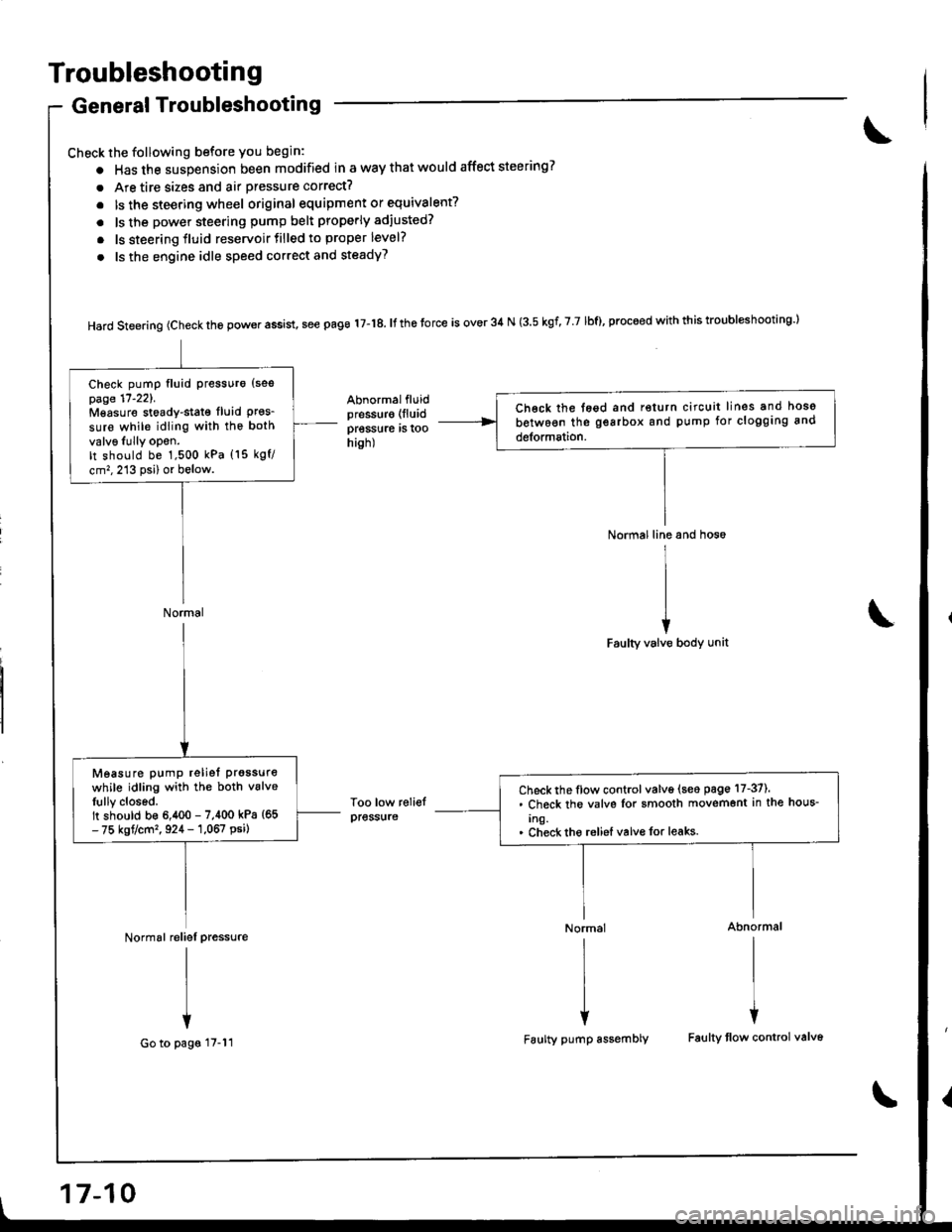
Troubleshooting
General Troubleshooting
Check the following before you begin:
o Has the suspension been modified in a way that would affect steering?
. Are tire sizes and air pressure correct?
. lsthe steering wheel original equipment or equivalent?
. ls the power steering pump belt properly adiusted?
. ls steering fluid reservoirtilled to proper level?
. ls the engine idle speed correct and steadyT
Hard steering (check the power assist, see page 17-18. It the torce is over 34 N (3.5 kgf, 7 7 lbf), proceed with this troubl*hooting l
Abnormalfluidpressur€ (lluid
pressure rs roohish)
Too low reliefpress{ire
Normal line and hos6
I
II
iFaulty valve body unit
Normal Abnormal
rlrl
l{
Faulty pump assembly Faulty tlow control valv6
Ch€ck the tegd and return circuit lines and hoso
between the gearbox and pump for clogging and
detormation.
Check pump fluid Pressuro {sespage 17'221.Mgasure stoady-stat€ fluid Pres_sure while idling with the both
valv6Iully opon.It should be 1,500 kPa (15 kgf/
cm,,213 psi) or below.
Normal
Check the flow control valve (seo page 17-37).. Check the valvs Ior smooth movemont in the hous-
Ing.. Check tho reliel valvo for leaks.
Measure pump reliet prgssure
while idling with the both vslveIully closed.It should b€ 6,400 - 7,400 kPa {65- 75 kgt/cm'�, 924 - 1,067 psi)
Normal reliel pressure
I
I
+
Go to pags 17-11
17-10
Page 660 of 1681
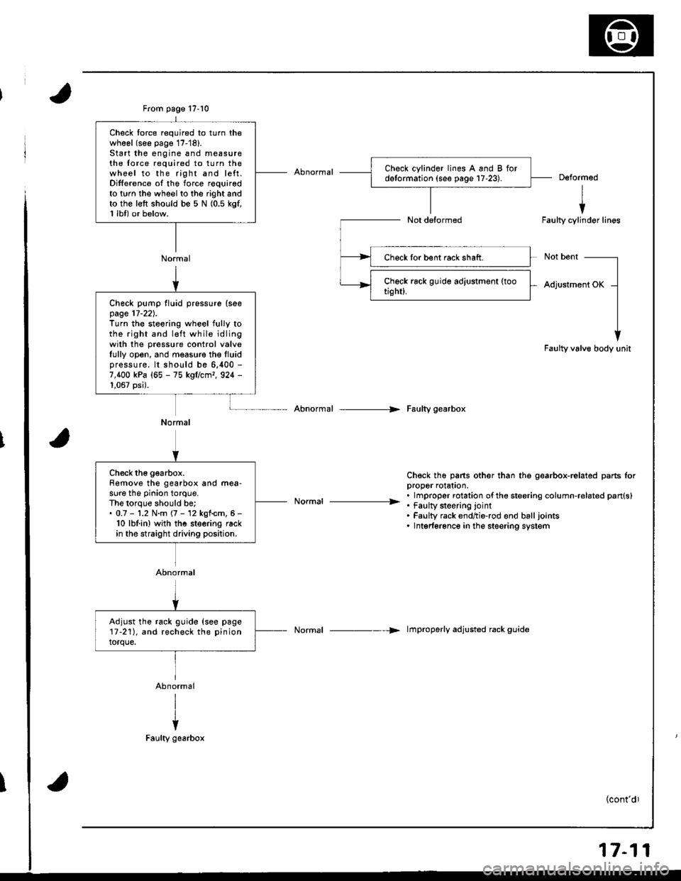
From page 17-10
Normal
Check lorce required to turn thewhool (see page 17-'18).Start the engine and measu16the force required to turn thewheel to the right and left.Difference of the force requiredto twn the wheel to the right andto the left should be 5 N (0.5 kgf,1 lbl) or below.
Deformed
I
iFaulty cylinder lines
Not bent
Adjustment OK
Faulty valve body unit
Abnormal --> Faulty gearbox
Ch€ck th6 pans other than the gearbox-related parts lorDrooer rolaton.
. . lmproper rotation ofthe steering column-related pan{s}----------------- . tau[y $eenng lornt. Faulty rack endtio-rod ond balljoints. Intgrferonce in the steering system
Normal -----> lmproperly adjusted rack guide
Check lor bent rack shaft.
Check pump fluid pressure (seepage 17-22).Turn the steoring wheel fully tothe right and l€ft while idlingwilh the pressure control valveIully open, and measure the Iluidpressure. lt should be 6,400 -
7,400 kPa (65 - 75 kgflcmr, 924 -
1,067 psi).
Normal
Ch€ck the gearbox.Remove the gearbox and mea-sure the pinion torque.The lorque should be;. 0.7 - '1.2 N.m (7 - 12 kgf.cm, 6 -
10 lbf.in) wjth the steering rackin the straight driving position.
Abnormal
Adjust the rack guide {see page17-211, and recheck the pinion
torque.
17-11
Page 662 of 1681
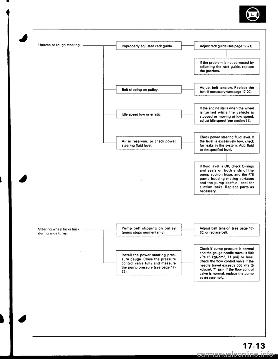
Unev€n or rough steering.Adjust rack guid€ (see page 17-21).
It the problem is not corrocted byadjusting the rack guid€, replacethe g€a.box.
Adjust b6ll tension. Ropl6ce theb6lt, it necossary {s€e p€ge 17-20).
lfth€ engine stalls when the wheelis turned while the vehic16 isstopped or moving at low speed.adjust idl6 sp6od (s€e s€ction 111.
ldle spoed low or €rratic.
Check powsr st6oring fuid lovel. lfthe lovel is exceggively low, ch6cktor leaks in the svstem. Add fluidto the sD6cilied l6v6l,
Air in r€gervoir, or check powsr
steering fluid lovel.
lf fluid level is OK, chock O-ringsand seals on both 6nds ot thepump suction hose. and the P/Spump housing mating surfacesand tho oumo shaft oil seal forsuction lgakr. Roplaco parts asn6c6ssary.
Pump b€lt slipping on pulloy(pump stops momentarily).Adiust b6lt t€nsion {s6e page '17-
20) or r6olac€ b€lt.
Chock if pump pressure is normaland the gauge needle trav€l is 500kPa (5 kgl/cm'�, 71 psi) or lesB.Ch€ck the flow control valvo if theno€dl€ trav€l oxco€ds 500 kPa {5kg7cml, 71 p6i). lf the flow controlvalve is normal. roplace the pumpas an assemDtv.
Install the power st66ring pr6s-
su16 gaug6. Close th6 prossure
control valve lully and m6asurethe pump prossure (see page'17-22t.
Ste€ring wheol kicks backduring wide turns.
7-13