belt HONDA INTEGRA 1998 4.G User Guide
[x] Cancel search | Manufacturer: HONDA, Model Year: 1998, Model line: INTEGRA, Model: HONDA INTEGRA 1998 4.GPages: 1681, PDF Size: 54.22 MB
Page 162 of 1681
I
i
Pistons
Installation (cont'dl
ll the crankshaft is not installed
1. Remove the connecting rod caps, then install the
ring compressor. and check that the bearing is
securely in place.
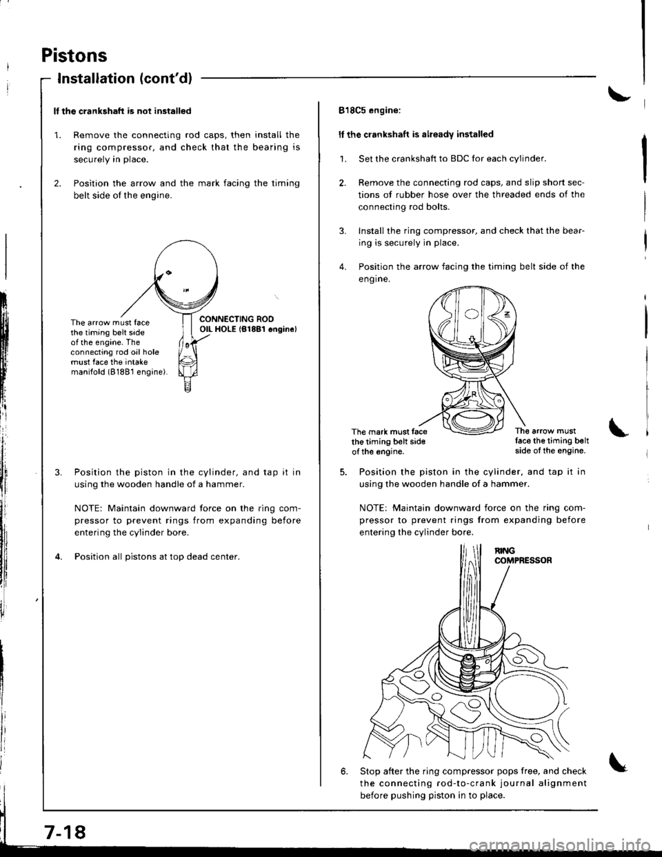
2. Position the arrow and the mark facing the timing
belt side of the engine.
ItIl
Iti
tfll|lflI[lrB
[:
i"lrt
i'
ff
ll,
illi
llillr
il
The arrow must facethe timing belt sideof the engine. Theconnecting rod oil holemust face the intakemanilold (8188'l engine).
Position the piston in the cylinder, and tap it in
using the wooden handle of a hammer.
NOTE: Maintain downward force on the ring com-
pressor to prevent rings from expanding before
entering the cylinder bore.
Position all pistons at top dead center.
7-18
818C5 engine:
ll the crankshaft is already installed
1. Set the crankshaft to BDC for each cylinder.
2. Remove the connecting rod caps, and slip short sec-
tions of rubber hose over the threaded ends of the
connecting rod bolts.
3. Install the ring compressor, and check that the bear-
ing is securely in place.
4. Position the arrow facing the timing belt side of the
eng ine.
The mark must facethe timing belt sideof the engine.
The arrow mustlace the timing beltside of the engine.
Position the piston in the cylinder, and tap it in
using the wooden handle of a hammer.
NOTE: Maintain downward iorce on the ring com-
pressor to prevent rings from expanding before
entering the cylinder bo.e.
6. Stop after the ring compressor pops free, and check
the connecting rod-to-crank journal alignment
before pushing piston in to place.
Page 163 of 1681
I
7.
8.
9.
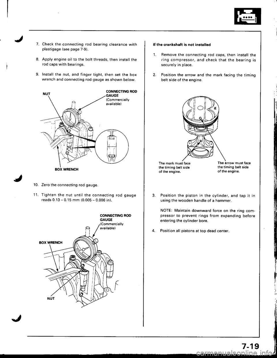
Check the sonnecting rod bearing clearance withplastigage (see page 7-9).
Apply engine oil to the bolt threads, then install the
rod caps with bearings.
Install the nut, and finger tight, then set the boxwrench and connecting rod gauge as shown below.
CONNCCNNG RODGAUGE{Commerciallyavailable)
10.
WRENCH
Zero the connecting rod gauge.
Tighten the nut until the connecting rod gauge
reads 0.13 - 0.15 mm (0.005 - 0.006 in).
CONNECNNG HOOGAUGE
1t.
ll the crankshaft is not installed
1. Remove the connecting rod caps, then install the
ring compressor, and check that the bearing is
securely in place.
2. Position the arrow and the mark facing the timing
belt side ot the engine.
The mark must facethe timing belt sideof the engine.
Tb6 arrow must tac6th€ timing belt sideof the engine.
Position the piston in the cylinder, and tap it in
using the wooden handle of a hammer.
NOTE: Maintain downward force on the ring com-pressor to prevent rings from expanding before
entering the cylinder bore.
Position all pistons at top dead center.
Page 166 of 1681
Piston Pins
Removal
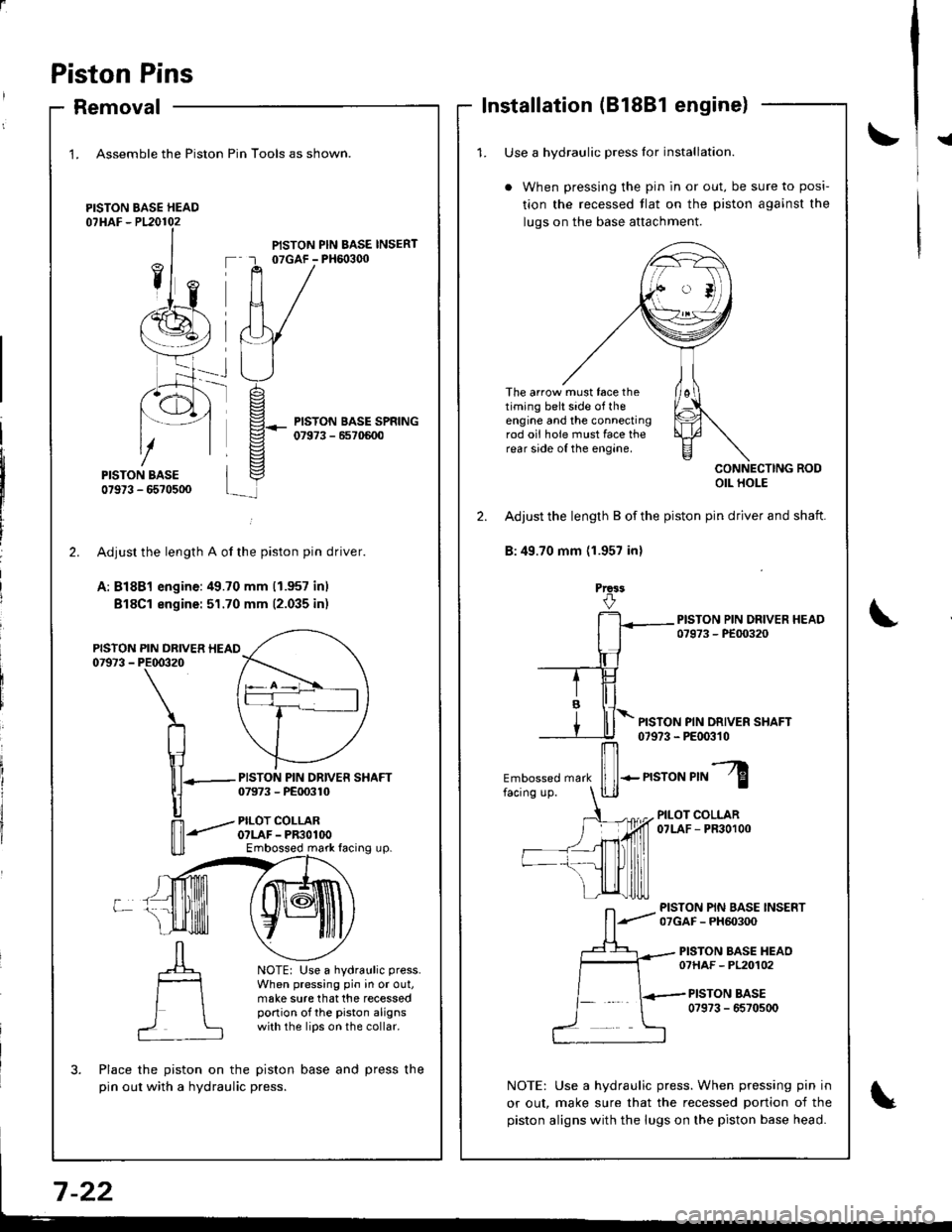
1. Assemble the Piston
PISTON BASE HEAD07HAF - P120102
Pin Tools as shown.
PISTON PIN BASE INSERT07GAF - PH6o3q)
PISTON BASE SPRING07973 - 6570600
-rt_
2.
PISTON07973 -
L
PISTON PIN DRIVER SHAFT07973 - PE00310
PILOT COLLARO?LAF - PR3OlOOEmbossed mark facing up.
NOTE: Use a hydraulic press.
When pressing pin in or out,make sure that the recessedportion of the piston alignswith the lips on the collar.
?
Adjusr the length A of the piston pin driver.
A: Bl8Bl engine:49.70 mm (1.957 inl
Bl8Cl engine: 51.70 mm (2.035 inr
PIN DRIVER HEAIPE00320
\
n
\1lll-
|]
n'-"'
Place the piston on the piston base and press the
pin out with a hydraulic press.
Installation (81881 engine)
!{1. Use a hvdraulic Dress lor installation.
When pressing the pin in or out, be sure to posi-
tion the recessed tlat on the piston against the
luqs on the base attachment.
The arrow must face thetiming belt side of theengine and the connectingrod oii hole must face therear side of the engine.
CONNECTING RODOIL HOLE
2. Adjust the length B of the piston pin driver and shaft.
B:49.70 mm (1.957 inl
Prca3
PISTON PIN DRIVER SHAFT07973 - PE00310
Embossed mark
ffi-n"ro"r,"l
PILOT COLLAR07LAF - PR30100
PISTON PIN BASE INSERT07GAF - PH60300
PISTON BASE HEAO07HAF - PL20102
PISTON BASE0?973 - 6570500
NOTE: Use a hydraulic press. When pressing pin in
or out, make sure that the recessed portion of the
piston aligns with the lugs on the piston base head.
Page 184 of 1681
3.
Removal/lnspection/lnstallation
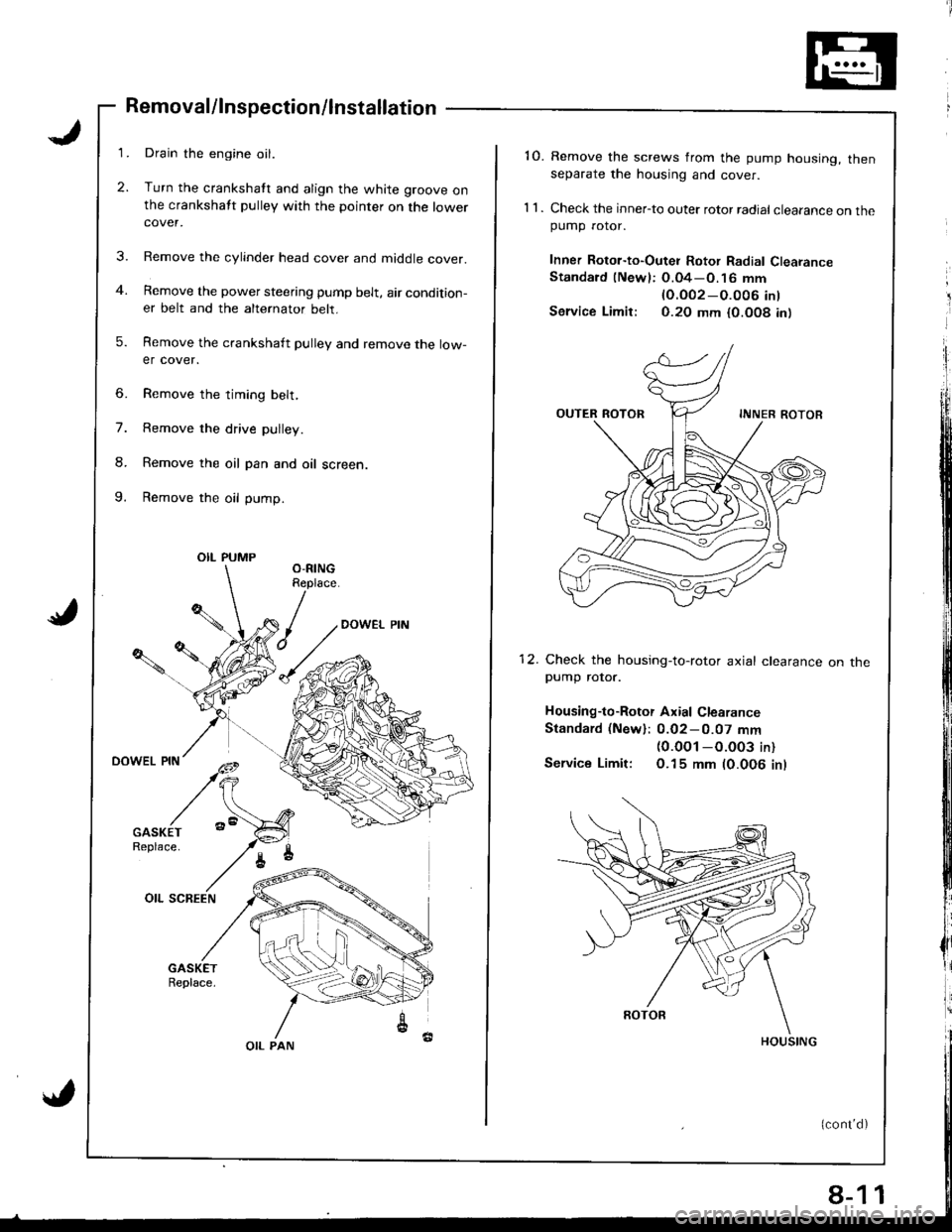
Drain the engine oil.
Turn the crankshatt and align the white groove onthe crankshatt pulley with the pointer on the lowercover.
Remove the cylinder head cover and middle cover.
Remove the power steering pump belt, air condition-er belt and the alternator belt.
Remove the crankshaft pulley and remove the low-er cover.
6. Remove the timing belt,
7. Remove the drive pulley.
8. Remove the oil pan and oil screen.
9. Remove the oil pump.
OIL PUMP
OIL PAN
8-1
'10. Remove the screws from the pump housing, thenseparate the housing and cover.
1 1 . Check the inner-to outer rotor radial clearance on thepumD rotor.
Inner Rotor-to-Outei Rotor Radial ClearanceStandard (Newl: O.04-O.16 mm
lO.OO2-O.O06 int
Service Limir: 0.20 mm {0.O08 in)
12. Check the housing-to-rotor axial clearancepump rotor.
Housing-to-Rotor Axial Clearance
Standard (New): 0.02-0.07 mm(0.0O1 -O.003 in)
Service Limit: O.15 mm (0.006 inl
on tne
1
Page 205 of 1681
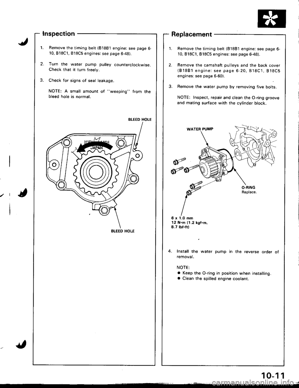
Inspection
Remove the timing belt (81881 engine: see page 6-10, B'l8Cl,818C5 engines: see page 6-48).
Tu.n the water pump pulley counterclockwise.Check that it turn freely.
Check for sign6 of seal leakage.
NOTE: A small amount of "weeping" trom thebleed hole is normal.
BLEED HOLE
Remove the timing belt (81881 engine: see page 6-
10,818C1, Bl8C5 engines: see page 6-48).
Remove the camshaft pulleys and the back cover(B'1881 engine: see page 6-20, 818C1, 818C5
engines: see page 6-60).
Remove the water pump by removing flve bolts.
NOTE: Inspect, repair and clean the O-ring groove
and mating surface with the cylinder block,
Replacement
6 x 1.0 mm12 N.m 11.2 kgt.m,8.7 tbf.tt)
4. Install the water pump in the reverse order ofremoval.
a Keep the O-ring in position when installing.a Clean the spilled engine coolant.
BLEED HOL€
10-1 1
Page 241 of 1681
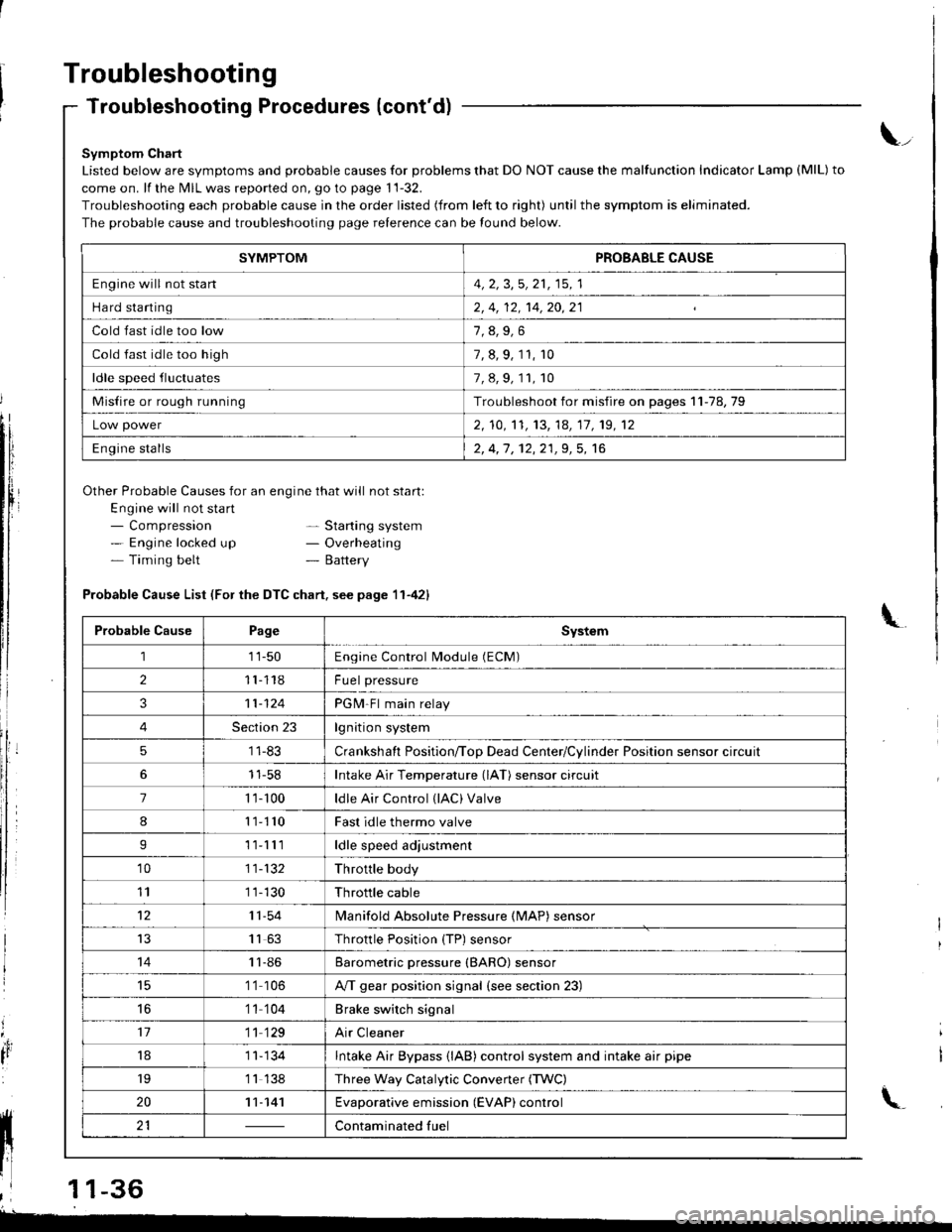
Troubleshooting
Troubleshooting Procedures (cont'd)
Symptom Chart
Listed below are symptoms and probable causes for problems that DO NOT cause the malfunction Indicator Lamp (MlL) to
come on. lf the MIL was reported on, go to page 11-32.
Troubleshooting each probable cause in the order listed (from left to right) until the symptom is eliminated.
The probable cause and troubleshooting page relerence can be found below.
Other Probable Causes for an engine that will not start:
Engine will not sta rt- Compression- Engine locked up- Timing belt
\_
- Starting system- Overheating- Battery
'4,
It
Probable Cause List (For the DTC chart. see page 11-421
Probable CausePageSystem
111-50Engine Control Module (ECM)
211118Fuel pressure
311-124PGM-Fl main relay
4Section 23lgnition system
51 1-83Crankshaft Position/ToD Dead Center/Cylinder Position sensor circuit
11-58Intake Air Temperature (lAT) sensor circuit
71 '�t- 100ldle Air Control (lAC) Valve
811110Fast idle thermo valve
I11lllldle speed adjustment
'1011-132Throttle body
111 1-130Throttle cable
1211-54lvlanifold Absolute Pressure {MAP) sensor
IJ1163Throttle Position {TP) sensor
1411-86Barometric pressure (BARO) sensor
1 '1 106A/T gear position signal {see section 23)
16'1 1 104Brake switch signal
1711 129Air Cleaner
181 1- 134Intake Air Bypass {lAB} control system and intake air pipe
19'1 1 138Three Way Catalytic Convener (TWC)
2011-141Evaporative emission (EVAP) control
21Contaminated fuelll ll 21 | - | cont"-in"t"o tu"
11 l-
I
,l 11-36
-
SYMPTOMPROBABLE CAUSE
Engine will not stan4, 2, 3,5, 21, 15, 1
Hard starting2, 4, 12, 14,20,21
Cold fast idle too low
Cold fast idle too high7, 8, 9, 11, r0
ldle speed fluctuates7,8,9,11,10
Misfire or rough runningTroubleshoot for misfire on pages 11-78,79
Low power2, 10,'t1, 13, 14, 17, 19, 12
Engine stalls2, 4,1 , 12,21,9, 5, 16
Page 248 of 1681
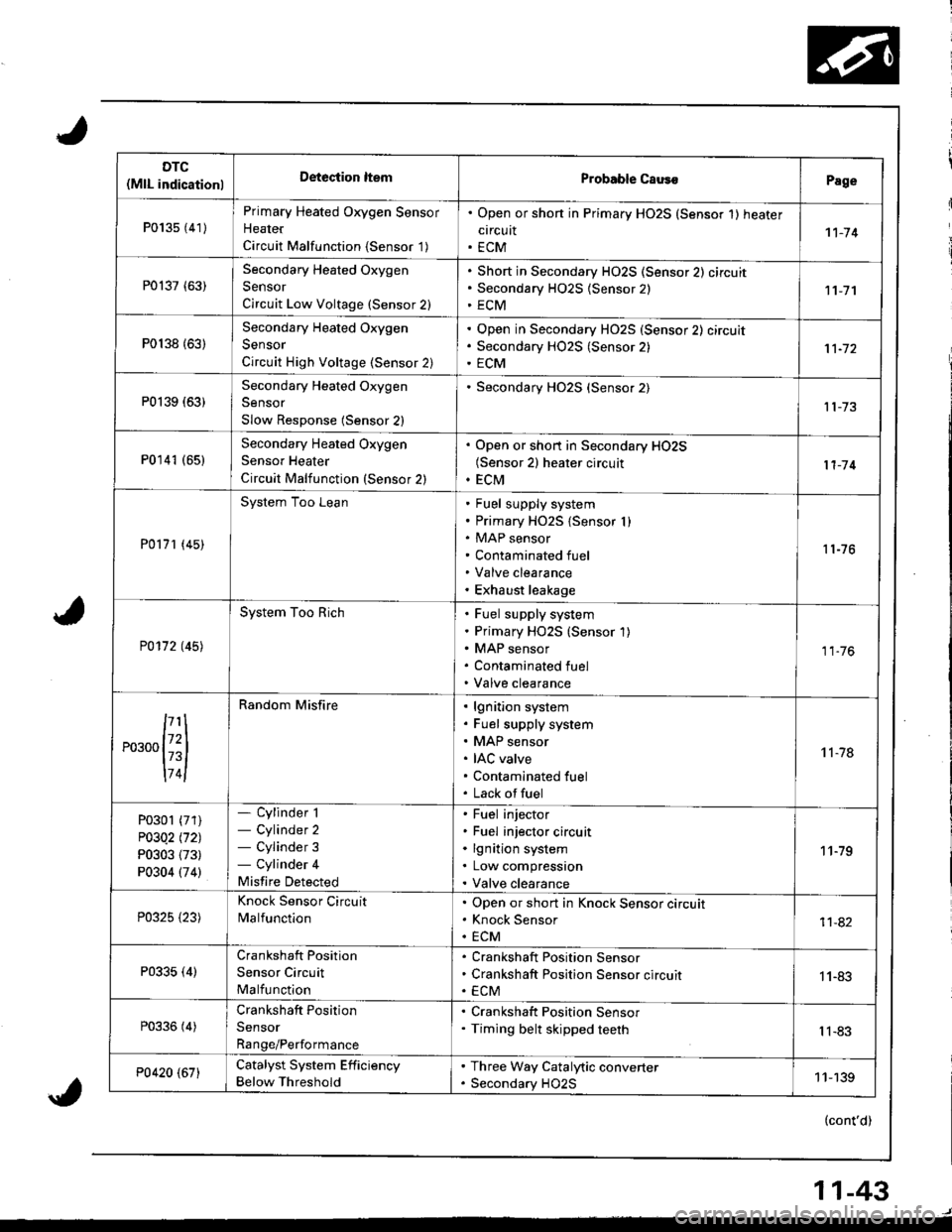
DTC(MlL indicationlDeteciion ltemProbable CausoPage
P013s {41)
Primary Heated Oxygen Sensor
Heater
Circuit Malfunction {Sensor '1)
. Open or shon in Primary HO2S (Sensor 1) heater
circuit. ECM1't-74
P0137 (63)Secondary Heated Oxygen
Sensor
Circuit Low Voltage (Sensor 2)
Short in Secondary HO2S (Sensor 2) circuit
Secondary H02S {Sensor 2)
ECM11-7'l
P0138 {63)
Secondary Heated Oxygen
Sensor
Circuit High Voltage (Sensor 2)
Open in Secondary HO2S (Sensor 2) circuit
Secondary HO2S (Sensor 2)
ECM
P0139 (63)Secondary Heated Oxygen
Sensor
Slow Response (Sensor 2)
Secondary HO2S (Sensor 2)
P0141 (651Secondary Heated Oxygen
Sensor Heater
Circuit Malfunction (Sensor 2)
. Open or short in Secondary HO2S(Sensor 2) heater circuit. ECM11-'14
P0171 (45)
System Too LeanFuel supply system
Primary HO2S {Sensor I )MAP sensor
Contaminated fuel
Valve clearance
Exhaust leakage
11-76
P0172 t45l
System Too RichFuel supply system
Primary HO2S (Sensor 1)
MAP sensor
Contaminated fuel
Valve clearance
11.76
,...,{iil
174l
Random Misfirelgnition system
Fuel supply system
MAP sensor
IAC valve
Contaminated fuel
Lack offuel
't 1-78
P0301 (71)
P03Q2 l'121
P0303 (73)
P0304 (74)
- Cylinder 1- Cylinder 2- Cylinder 3- Cylinder 4
Misfire Detected
Fuel injector
Fuel injector circuit
lgnition system
Low compression
Valve clearance
11-79
P0325 {23)
Knock Sensor Circuit
MalfunctionOpen or short in Knock Sensor circuit
Knock Sensor
ECM11-82
P0335 (4)Crankshaft Position
Sensor Circuit
Malfunction
Crankshaft Position Sensor
Crankshaft Position Sensor circuit
ECM1 1-83
P0336 (4)Crankshaft Position
Sensor
Range/Performance
. Crankshaft Position Sensor. Timing belt skipped teethIl-83
P0420 (67)Catalyst System Efficiency
Below Threshold
. Three Way Catalytic converter. Secondary HO2S11-139
(cont'd)
11-43
Page 651 of 1681
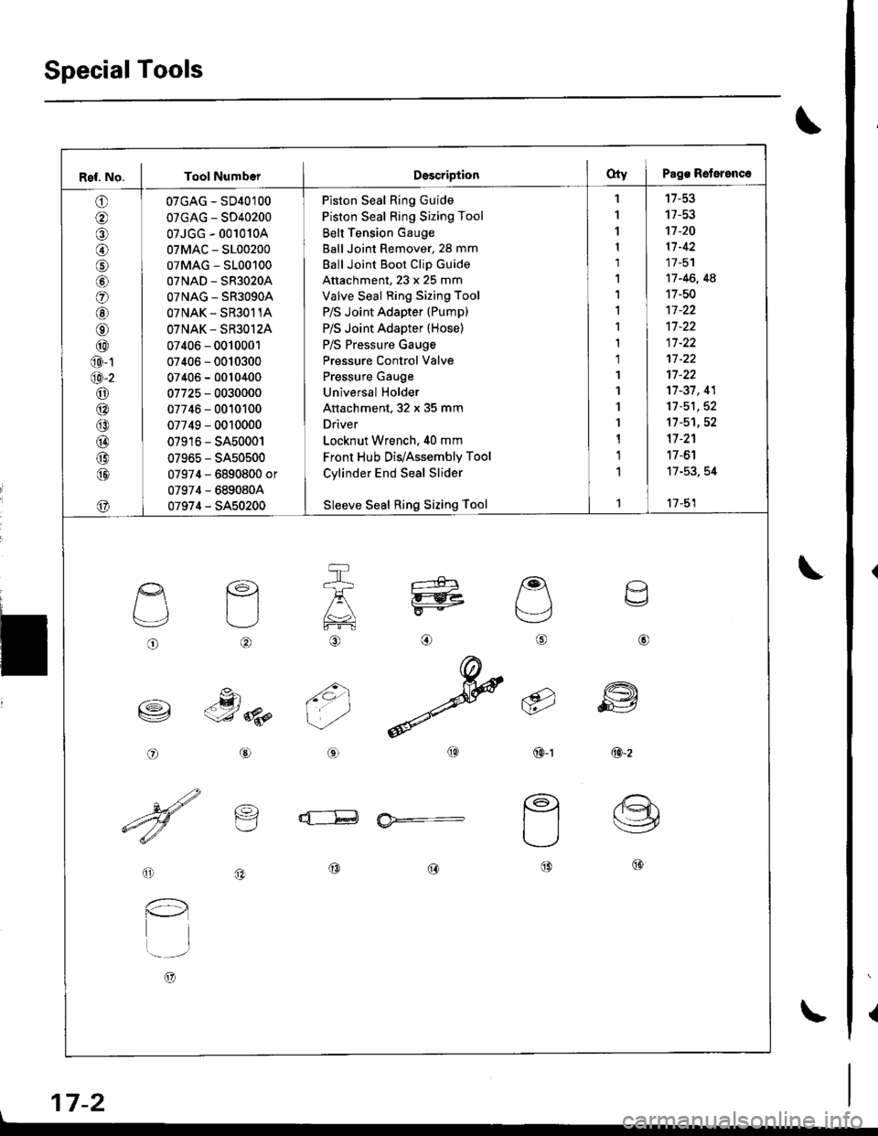
SpecialTools
{
\
\
17-2
Ref. No. I Tool NumberDsscriptionOty I Pags Reterenc.
o
@
@
o
@
@
@
@
@
@-1
@-2
o6:^
@
@
@
@
@
07GAG - SD40100
07GAG - SD40200
07JGG - 001010A
07MAC - S100200
07MAG - S100100
07NAD - SR3020A
OTNAG _ SR3OgOA
OTNAK - SR3O11A
OTNAK - SR3O12A
07406 - 0010001
07406 - 0010300
07406 - 0010400
07725 - 0030000
07746 - 0010100
07749 - 0010000
07916 - SA50001
07965 - SA50500
07974 - 6890800 or
07974 - 6890804
07974 - SA50200
Piston Seal Ring Guide
Piston Seal Ring Sizing Tool
Belt Tension Gauge
Ball Joint Remover, 28 mm
Ball Joint Boot Clip Guide
Attachment, 23 x 25 mm
Valve Seal Ring Sizing Tool
P/S Joint Adapter (Pump)
P/S Joint Adapter (Hose)
P/S Pressure Gauge
Pressure Control Valve
Pressure Gauge
Universal Holder
Attachment, 32 x 35 mm
Driver
Locknut Wrench. 40 mm
Front Hub Dis/Assembly Tool
Cylinder End Seal Slider
Sleeve Seal Ring Sizing Tool
'I
1
1
1
1'|
1,l
I
1
1
1'I
'l
1
1
1
1
1
't7-53
17-53't]-20
11-42
17 -51
17 -46, 4A
17-50
17-37, 41
11-51,52't1-51,52
17 -2'�1
17 -6'l
17-53. 54
17-51
o
L'4,
o
€)
-g)c-J 8p
@
@
6i
(9')\E/'
@-t
a
6
ffi
@-z
d--E ia*=-
o
l-l
t..-_-.r
A)
@@@
\
Page 652 of 1681
I
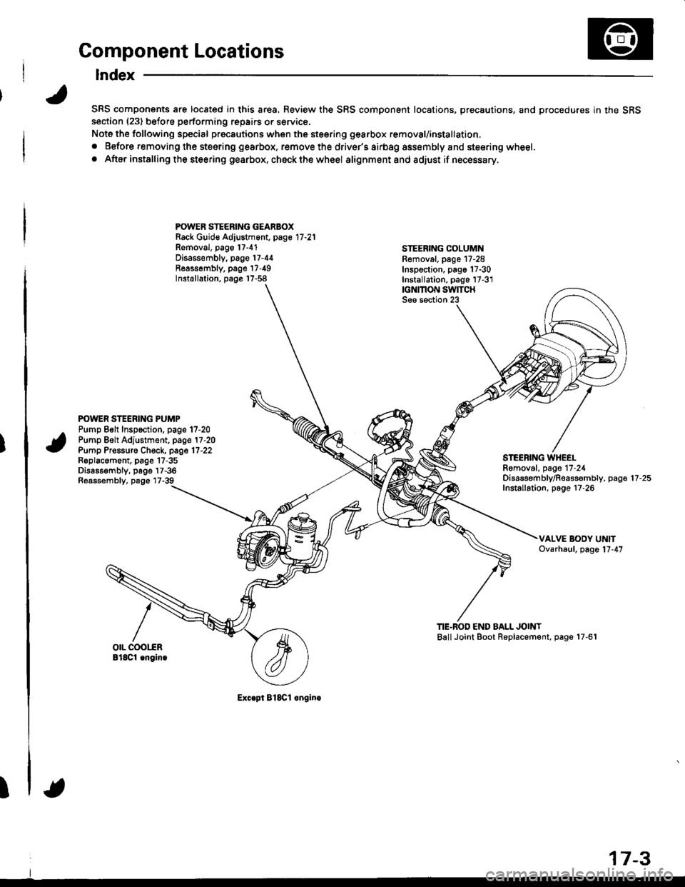
Component Locations
Index
SRS components are located in this area. Review the SRS component locations, precautions, and procedures in the SRSsection (23) before performing repairs or service.
Note the following special precautions when the steering gearbox removal/installation,
. Before removing the steering gearbox, remove the driver's airbag assembly and steering wheel.
. After installing the steering gearbox, ch6ck the wheel alignmentand adjust if necessary.
POWER STEERING GEARBOXRack Guid€ Adjustment, page 17 -21
Removal, pago 17-4'1Disassembly, page 17-44Reassombly. page'17-49Installation, page 17-58
STEEBING COLUMNRemoval. page 17-28Inspection, pago 17-30Installation, page 17-3'1|GNMON SWITCHSee section 23
POWER STEERING PUMPPump Belt Inspection. page 17-20Pump Belt Adjustment, page 17 -20
Pump Pr€ssuro Check, page 17'22Roplacament, page 17-35Dis686embly, page 17-36Reassembly, page 17-39
STEEBING WHEELRomoval, page 17-24Disassembf y/Reassembly, paga 17 -25
Installation, page 17-26
TIE.BOD END BALL JOINTBallJoint Boot Replacement, page 17-61
Exc.pt BlSCl onginc
17-3
Page 654 of 1681
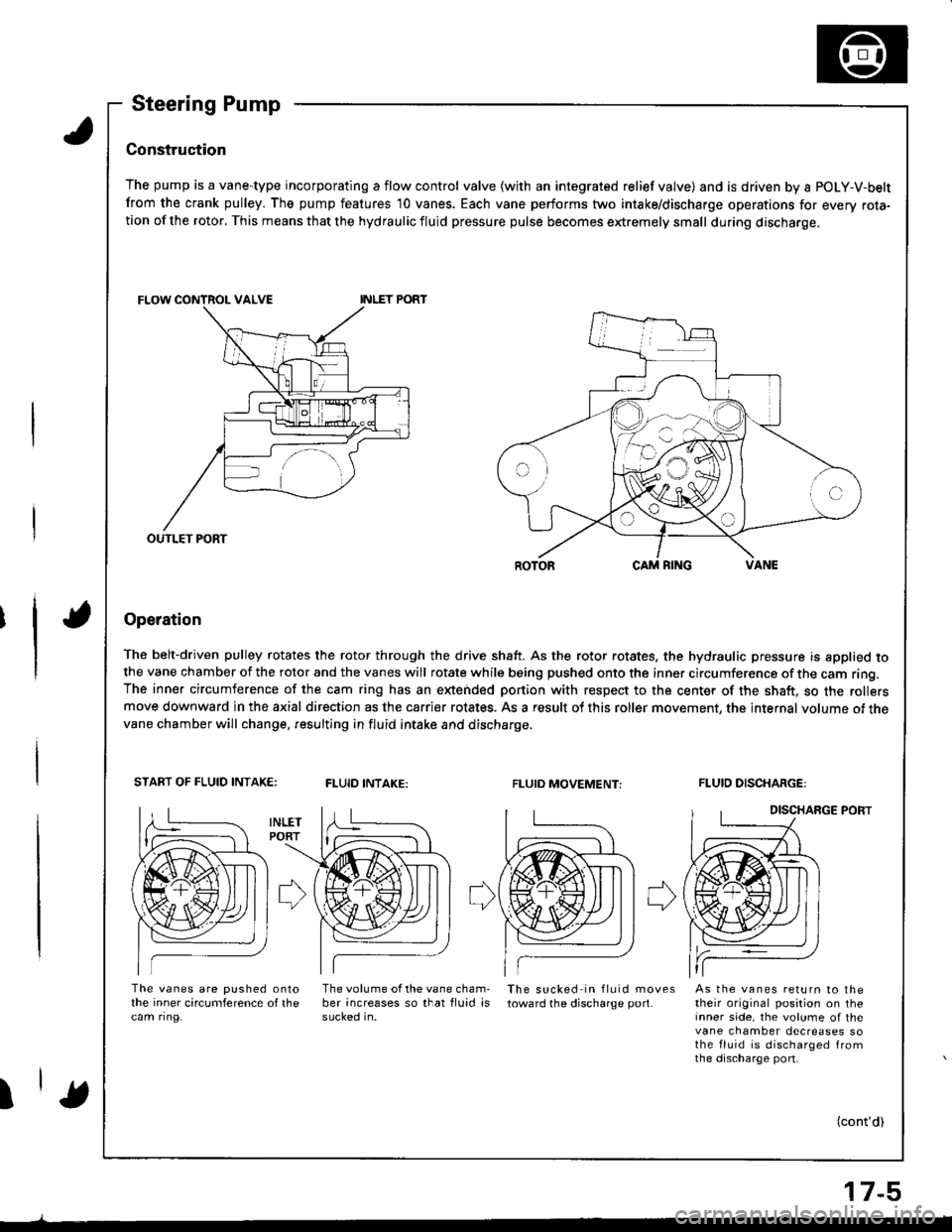
Steering Pump
Construc'tion
The pump is a vane-type incorporating a flow control valve (with an integrated relief valve) and is driven by a POLY-V-belt
from the crank pulley. The pump features 10 vanes. Each vane performs two intake/discharge operations for every rota-tion of the rotor. This means that the hydraulic fluid pressure pulse becomes extremely small during discharge.
Operation
The belt-driven pulley rotates the rotor through the drive shaft. As the rotor rotates. the hydraulic pressure is applied tothe vane chamber of the rotor and the vanes will rotate while being pushed onto the inner circumference of the cam ring.The inner circumference of the cam ring has an extended portion with respect to the center of the shaft, so the rollersmove downward in the axial direction as the carrier rotates. As a result of this roller movement, the internal volume of thevane chamber will change. resulting in fluid intake and discharge.
START OF FLUID INTAK€:FLUID INTAKE:FLUIO MOVEMENT:FLUID DISCHARGE:
DISCHARGE PORT
The vanes are pushed onlothe inner circumference of thecam ring.
The volume of the vane cham-ber increases so that fluid issucked in.
The sucked in fluid movestoward the discharge port.As the vanes return to thetheir original position on theinner side, the volume of thevane chamber decreases sothe fluid is discharged fromthe discharge port-
I(cont'd)
OUTLET PORT
17-5