brake sensor HONDA INTEGRA 1998 4.G User Guide
[x] Cancel search | Manufacturer: HONDA, Model Year: 1998, Model line: INTEGRA, Model: HONDA INTEGRA 1998 4.GPages: 1681, PDF Size: 54.22 MB
Page 511 of 1681
Road Test
NOTE: Warm up the engine to operating temperature (the radiator fan comes on).
1. Apply parking brake and block the wheels. Start the engine, then shift to @ position while depressing the brake pedal-
Depress the accelerator pedal, and release it suddenly. The engine should not stall.
2. Repeat same test in E position.
3. Test drive the vehicle on a flat road in the @ position. Check that the shift points occur at approximate speeds shown.
Also check for abnormal noise and clutch slippage.
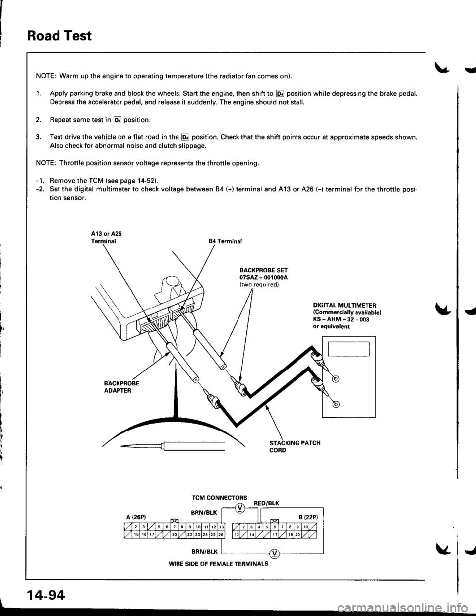
NOTE: Throttle position sensor voltage represents the throttle opening.
-1. Remove the TCM (see page 14-52).-2. Set the digital multimeter to check voltage between 84 (+) terminal and A13 or A26 (-) terminal for the throttle posi-
tion sensor.
84 Terminal
DIGITAL MULTIMETER(Commercially availablelKS - AHM -32 - 003oa oquivalent
, 14-94
TCM CONNECTORS
WIRE SIDE OF FEMALE TERMINALS
i
J
Page 513 of 1681
Road Test
(cont'dl
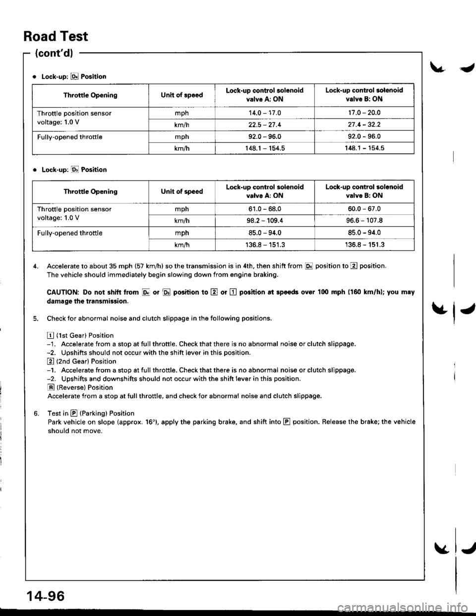
Lock-up: E Position
. Lock-up: Ell Position
4. Accelerate to about 35 mph (57 km/h) so the transmission is in 4th, then shitt from E position to E position.
The vehicle should immediately begin slowing down from engine braking.
CAUTION: Do noi shitt lrom I or $ position to E or E position 8t speeds over l0o mph (160 km/h); you may
damage the transmission.
5. Check for abnormal noise and clutch slippage in the following positions,
E {1st Gear} Position-1. Accelerate from a stop at fullthrottle. Check that there is no abnormal noise or clutch slippage.-2. Upshifts should not occur with the shift lever in this position.
E (2nd Gear) Position-1. Accelerate from a stop atfull throttle. Check that there is noabnormal noiseorclutch slippage.-2. Upshifts and downshifts should not occur with the shift lever in this position.
E (Reverse) Position
Accelerate from a stop at tull throttle, and check for abnormal noise and clutch slippage.
6. Test in E (Parking) Position
Park vehicle on slope {app.ox. 16'}, apply the parking brake, and shift into E position. Release the brake; the vehicle
should not move.
Throttle OpeningUnit of spoedLock-up control solenoid
valve A: ON
Lock-up contlol solenoid
valve B: ON
Throttle position sensor
voltage: 1.0 V
mph14.0 - 17.017 .0 - 20.0
km/h22.5 - 27 .427 .4 - 32.2
Fully-opened throftlemph92.0 - 96.092.0 - 96.0
km/h148.1 - 154.5148.1- 154.5
Throttle OpeningUnit of speedLock-up conirol 3olenoid
valve A: ON
Lock-up control solonoid
valvs B: ON
Throttle position sensor
voltage: 1.0 V
mph61.0 - 68.060.0 - 67.0
km/h98.2 - 109.496.6 - 107.8
Fully-opened throttlempn85.0 - 94.085.0 - 94.0
km/h136.8 - 151.3'136.8 - 151.3
14-96
-
Page 521 of 1681
Transmission
Removal
. Make sure lifts, iacks and salety stands are placed
properly, and hoist brackets are attached to lhe cor-
rect position on the engine (see section 11.
. Apply parking brake and block real wheels, so vehi-
cle will nol roll off stands and fall on you while work-
ing under it.
CAUTION: Use fender covers to avoid damaging paint-
ed surtaces.
1 . Disconnect the battery negative (- ) and positive { + )
cables from the battery.
2. Remove the intake air duct and air cleaner housing
assemoty.
AIR CLEANERHOUSING ASSEMBLY
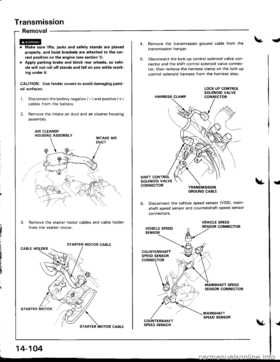
Remove the starter motor cables and cable holder
from the starter motor.
MOTOR CABLECABLE HOLDER
STARTER MOTOR'/,/ \
STARTER MOTOR CABI-E
14-104
-
5.
Remove the transmission ground cable from the
transmission hanger.
Disconnect the lock-up control solenoid valve con-
nector and the shift control solenoid valve connec-
tor, then remove the harness clamp on the lock-up
control solenoid harness from the harness s1ay.
HARNESS CLAMP
TRANSMISSIOIGROUND CABLE
Disconnect the vehicle speed sensor (VSS), main-
shalt speed sensor and countershalt speed sensor
connecrors.
{
6.
VEHICLE SPEED
VEHICLE SPEED
ll t2tor coNNEcroR
V
MAINSHAFT SPEEDSENSOR CONNECTOR
MAINSHAFTSPEED SENSORCOUNTERSHAFTSPEED SENSOR{
Page 526 of 1681
L
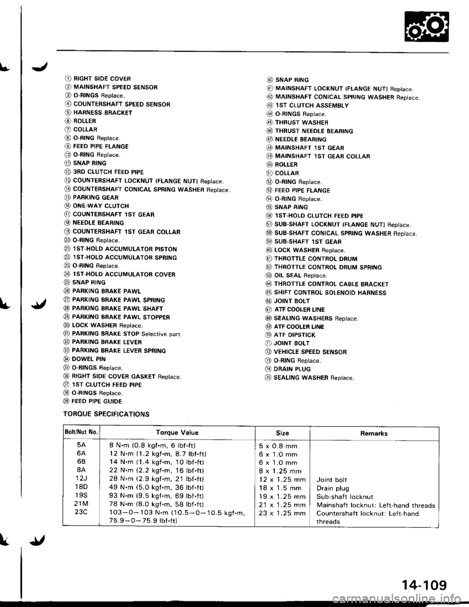
(t RtcHT sroE covER
@ MAINSHAFT sPEEo sENsoR(O O-RINGS Reptace.
@ couNTERSHAFT spEEo sENsoR
@ HARNESS BRACKET
@ RoLLER
O coLLAR
@ O-RING Replace.
@ FEEo PIPE FLANGE
@ o-RtNG Reptace.
O) SNAP RING
@ 3RD cLUTcH FEED PIPE
@ COUNTERSHAFT LocKNUT (FLANGE NUT) RepIace,
@ couNTERSHAFT CONtcAL spRtNG wAsHER Reptace.
@ PARKING GEAR
G) ONE-WAY cLUTcH
@ COUNTERSHAFT lST GEAR
@ NEEoLE BEARTNG
@ COUNTERSHAFT 1ST GEAR COLLAR
€0 o-RING Reprace.
@ 1sT-HoLD AccUMULAToR ptsTok
@ 1sr-HoLD AccUMULAToR spRtNG
@ o-RING Reptace.
@ rsr-HoLD AccUMULAToR covER
@ SNAP RING
@ PARKING BRAKE PAWL
@ PARKING BRAKE PAWL SPRING
€0 PARKTNG BRAKE PAWL SHAFT
@ PARKTNG BRAKE pawl sroppER
€0 LOCK WASHEF Replace.
@ PARKTNG BRAKE STOP Setecrive oart
@ PARKING BRAKE LEVER
@ PARKING ERAKE LEVER SPRING
@ DowEL PrN
@ o-RlNGs Reptace.
@ RtcHT StOE COVER GASKET Reptace.
@ 1sr cLUTcH FEED ptpE
@ O-R|NGS Reptace.
@ FEEO P|PE GUTOE
TOROUE SPECIFICATIONS
@ SNAP R|NG
@ MAINSHAFT LocKNUT (FLANGE NUT) Replace
@ MAtNSHAFT coNtcAL spRtNG wAsHER Reptace.
@ 1sT clurcH ASSEMBLY
@ O-RINGS Reptace.(4D THRUST wASHEB
@ THRUST NEEDLE EEARING
@) NEEDLE EEARING
@ MAINSHAFT 1sT GEAB
@ MAINSHAFT ,IsT GEAR coLLAR
@ ROLLER
€) coLLAR
@ o-R|NG Reptace.
@ FEED PIPE FLANGE
@ o-RtNG Reptace.
@ SNAP RING
@ 1sT-HoLD cLUTcH FE€D ptpE
@ SUB-SHAFT LOCKNUT TFLANGE NUT) Reptace.
@ suB-SHAFT CONTCAL SpRtNG WASHER Reptace.
@ SUB-SHAFT 1sT GEAR
@ LocK WASHER Reptace.
@ THRoTTLE coNTRoL DRUM
6, THRoTTLE coNTRoL DRUM SPRING
@ OIL SEAL Replace.
@ THRoTTLE coNTRoL cAELE BRAGKET
@ sHtFT coNTRoL soLENoto HARNESS
G0) JOINT BOLT
@ ATF COOLER LINE
@ SEAL|NG wASHERS Reptace.
@ ATF cooLER LINE
@ ATF DrPsflcK
@ JOINT BoLT
@ vEHrcLE SPEED sENsoR
@ o-RING Reptace.
(, DRAIN PLUG
@ SEAL|NG wasHER Replace.
Bolti Nut No.Torque ValueSizeRemarks
5A
6A
6B
8A
12J
18D
r9s
21M
23C
8 N.m (0.8 kgf.m, 6 lbf'ft)
12 N.m (1.2 kgf.m,8.7 lbf.ft)
14 N.m { 1 .4 kgf .m, 1 0 lbf .ft)
22 N'm 12.2 kgf 'm, 16 lbf .ft)
28 N.m (2.9 kgf.m. 2'1 lbl.It)
49 N.m {5.O kgl.m, 36 lbf.tt)
93 N.m (9.5 kgt.m, 69 lbf.tt)
78 N.m (8.0 kgt.m, 58 lbf .ft)
103-O- 103 N.m (1O.5 - O- 10.5 kgf.m.7 5.9 - O- 75.9 tbt.ft)
5xO.8mm
6 x 1.O mm
6 x 1.O mm
8 x 1.25 mm
12x1.25mm
18 x 1.5 mm
19 x 1.25 mm
2t x |.25 mm
23 x 1.25 mm
Joint bolt
Drain plug
Sub-shaft locknut
Mainshaft locknut: Left-hand threads
Countershaft locknut: Left hand
threads
{l
14-109
Page 587 of 1681
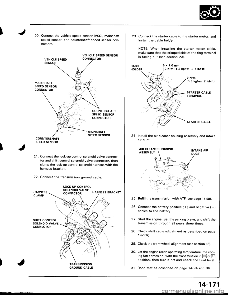
I20.Connect the vehicle speed sensor (VSS), mainshaft
speed sensor, and countershaft sDeed sensor con-
nectors.
VEHICLE SPEED SENSORCONNECTOB
)
k/
t"J
21. Connect the lock-up control solenoid valve connec-
tor and shift control solenoid valve conneclor, then
clamp the lock-up control solenoid harness with the
harness bracket.
22. Connect the transmission ground cable.
SPEED SENSOR
LOCK-UP CONTROLSOLENOID VALVECONNECTOR
23.Connect the starter cable to the starter motor, and
install the cable holder.
NOTE: When installing the starter motor cable,
make sure that the crimped side ol the ring terminal
is facing out (see section 23).
6 x 1.0 mm12 N.m {1 .2 kgf.m, 8.7 lbl.ft)
9 N.m(0.9 kgf.m, 7 lbt.ttl
STARTER CABLETERMINAL
STARTER CABLE
24.Install the air cleaner housing assembly and intake
arr oucl.
AIR CLEANER HOUSINGINTAKE AIRASSEMBLY
27.
Refill the transmission with ATF {see page 14-98).
Connect the battery positive (+ ) and negative { - }cables to the battery.
Start the engine. Set the parking brake, and shift the
transmission through all gears three times.
Check shilt cable adjustment as described on page
14-176.
Check the front wheel alignment (see section 18).
Let the engine reach operating temperature (the cool-ing fan comes onl with the transmission in S or @position, then turn it off and check the fluid level.
31. Road test as described on page 14-94 and 96.
25.
26.
24.
29.
30.
14-171
Page 721 of 1681
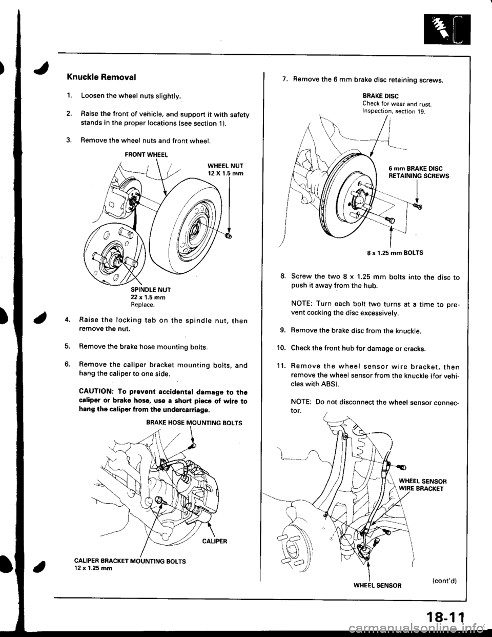
1.
Knuckle Removal
Loosen the wheel nuts slightly.
Raise the front of vehicle. and support it with safetystands in the proper locations {see section l ).
B€move the wheel nuts and front wheel.
SPINDLE NUT22 x 1.5 mmReplace.
Raise the locking tab on the
remove the nut.
spindle nut. then
Remove the brake hose mounting bolts.
Remove the caliper bracket mounting bolts, andhang the caliper to one side.
CAUTION: To pravant accidental damage to thgcaliper or braks hoso, use a shqrt piece of wirs tohsng the c8liper flom the undercarriage.
CALIPER BRACKET MOUNTING BOLTS12 x 1.25 mm
7, Remove the 6 mm brake disc retaining screws.
BRAKE DISCCheck for wear and rust.Inspection, section j9.
8. Screw the two I x L25 mm bolts into the disc topush it awav from the hub.
NOTE: Turn each bolt two turns at a time to pre-
vent cocking the disc excessively.
Remove the brake disc from the knuckle.
Check the front hub for damage or cracks.
Remove the wheel sensor wire bracket, thenremove the wheel sensor lrom the knuckle (for vehi-cles with ABS).
NOTE: Do not disconnect the wheel sensor connec-ror.
4.
6.
10.
11.
WHEEL SENSOFWIRE BRACKET
FRONT WHEEL
8 x 1.25 mm BOLTS
WHEEL SENSOR(cont'd)
Page 726 of 1681
Front Suspension
Knuckle/Hub (cont'd)
Knuckle lnstallation
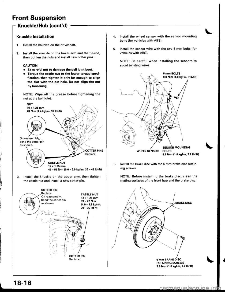
1. lnstall the knuckle on the driveshaft.
2. lnstall the knuckle on the lower arm and the tie-rod,
then tighten the nuts and install new cotter pins.
CAUTION:
. Be carelul not to damage tho ball ioint boot.
a Torque the castls nut to the lowel torque spgci-
fication, then tight€n it only far enough to align
the slot with the pin hole. Do not align the nut
by loosening.
NOTE: Wipe off the grease before tightening the
nut at the ball joint.
NUT
ri
10 x 1.25 mm4il N.m (4.{ kgtm,32lbf.ftl
On reassembly,bend the cotter pin
as shown.
CASTLE NUT12 x 1 .25 mm49 - 59 N.m (5.0 - 6.0 kgf m, 36 -,|i| lbf ft)
3. Install the knuckle on the upper arm, then tighten
the castle nut and install a new cotter Din.
COTTER PINReplace.On reassembly,bend the cotter pin
CASTLE NUT12 x 1.25 mm39 - 47 N.m{4.0 - 4.8 kgf.m,29 - 3s rbr.ft)
;
, 'ar
COTTER PIN
18-16
4.Install the wheel sensor with the sensor mounting
bolts (tor vehicles with ABS).
lnstall the sensor wire with the two 5 mm bolts (for
vehicles with ABS).
NOTE: Be careful when installing the sensors to
avoid twisting wires.
6 mm BOLTS9.8 N.m 11.0 kgf.m,7 lbf.ftl
v_)
SENSOR MOUNTINGBOLTS9.8 N.m (1.0 kgf.m,7.2 lbl.ftl
6. lnstall the brake disc with the 6 mm brake disc retain-
Ing screws.
NOTE: Before installing the brake disc, clean the
mating surfaces of the front hub and the brake disc.
6 mm BRAKE DISCRETAINING SCREWS9.8 N.m 11.0 kgl.m, 7.2 lbf'ftl
Page 775 of 1681
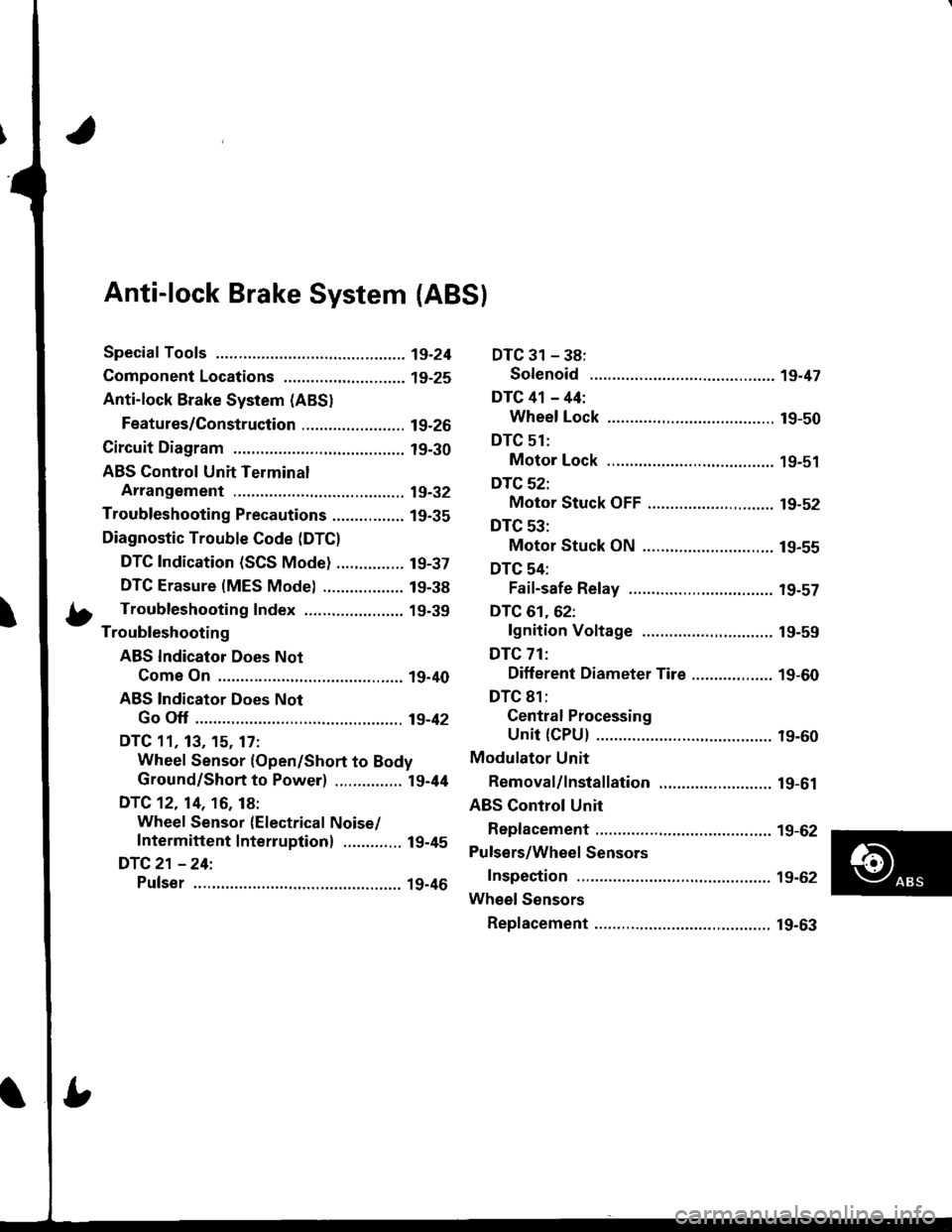
Anti-lock Brake System {ABS}
Speciaf Tools ............... 19-24
Component Locations,...........,..,........... 19-25
Anti-lock Brake System (ABSI
Features/Construction ....................... 19-2G
Circuit Diagram ........... 19-30
ABS Control Unit Terminal
Arrangement ........... 19-32
Troubleshooting Precautions ................ 1g-35
Diagnostic Trouble Code (DTC)
DTC Indication (SCS Mode) ............... t9-37
DTC Erasure {MES Mode) .................. 19-38
b Troubleshooting Index ...................... 19-39- Troubleshooting
ABS Indicator Does Not
Come On .............. 19-40
ABS Indicator Does Not
Go Off .............. ..... 19-42
DTC 11, 13, 15. 17:
Wheel Sensor (Open/Short to Body
Ground/Short to Power) ............... l9-44
DTC 12. 14, 16, 18:
Wheel Sensor (Electrical Noise/
Intermittent Interruption) ..........,.. 19-45
DTC21 -24:
Pulser ...,.......... ..... 19-46
DTC 31 - 38:
Solenoid .............. 19-47
DTC 41 - 44:
Wheel Lock .......... 19-50
DTC 51:
Motor Lock .......... 19-51
DTC 52:
Motor Stuck OFF ...................,........ 19-52
DTC 53:
Motor Stuck ON ............................. 19-55
DTC 54:
Fail-safe Relay ................................ t9-57
DTC 61.62:
lgnition Voltage ............................. 19-59
DTC 71:
Different Diameter Tire .................. 1 9-60
DTC 81:
Gentral Processing
Unit {CPU} ............ 19-60
Modulator Unit
Bemoval/lnstallation ......................... 19-61
ABS Control Unit
Replacement ............ 19-62
Pulsers/Wheel Sensors
Inspection ................ 19-62
Wheel Sensors
Replacement .,.......... 19-63
Page 784 of 1681
![HONDA INTEGRA 1998 4.G User Guide ABS Gontrol Unit Terminal Arrangement
ABS CONTROL UN]T 22P CONNECTOR
Wire side oI female t6rminals
Terminal
numbel
Wire
Golor
Terminsl sign
{Terminal
namet
Description
Measurgmgnt
TerminalConditions
{ HONDA INTEGRA 1998 4.G User Guide ABS Gontrol Unit Terminal Arrangement
ABS CONTROL UN]T 22P CONNECTOR
Wire side oI female t6rminals
Terminal
numbel
Wire
Golor
Terminsl sign
{Terminal
namet
Description
Measurgmgnt
TerminalConditions
{](/img/13/6069/w960_6069-783.png)
ABS Gontrol Unit Terminal Arrangement
ABS CONTROL UN]T 22P CONNECTOR
Wire side oI female t6rminals
Terminal
numbel
Wire
Golor
Terminsl sign
{Terminal
namet
Description
Measurgmgnt
TerminalConditions
{lgnition swhch ON {ll}}Voltage
1BLK/WHTGND3(Ground 3)
Ground1.GNDBelow 0.3 V
4GRN/REDPARK
{Parking)
Detects parking brake
switch signal4-GNDParking
brake
PulledBelow 0.3 V
Battery voltage
LT GRN/
BLK
FLW (-)
{FronLleft
wheel negative)
Detects left-front wheel
sensor srgnal
0.053 V or
above
0sci\oscope:
0.15 Vp-p or
above
7GBN/ORN
FLW (+)
(Front-left
wheel positive)- | Turn wheel at
E
1 turntsecona
l'GRN
FRW (-)
(Front-right
wheel negative)
Detects right-f ront wheel
sensor slgnal
8-9
1 FR\N (+)
I \GRN/BLK (Front-right
I I wheelpositiveStops0.25 - 1.15 V
10GRN/WHTSTOPDetects brake switch signal1O.GNDBrake pedalDepressedBaftery voltage
ReleasedBelow 0.3 V
11BLK/TELtG2
(lgnition 2)
Power source for activating
the system11-GNDlgnition
switch
oN {I)Battery voltage
Start (lll)Below 0.3 V
19-32
Page 1058 of 1681
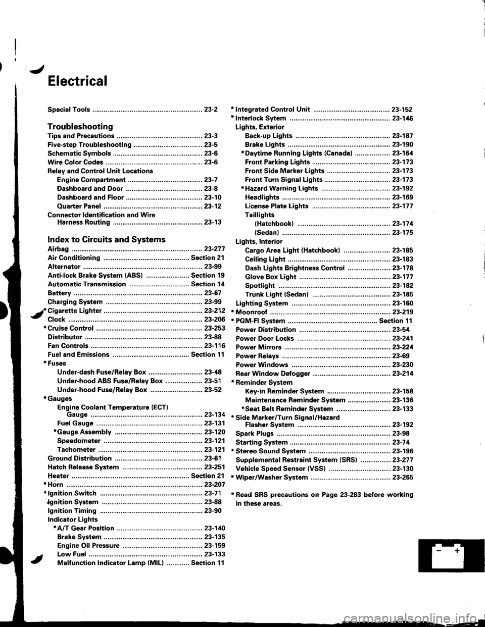
J
Electrical
Speciaf Toofs ..........................23-2
Troubleshooting
Tips 8nd Precautions .......................,..,.,.,.,.,......,..., 23-3
Five-step Troubleshooting ............,......,.,.,...,..,....., 23-5
Schsmatic Svmbols ...............23-6
Wire Color Code3 .. ................. 23-6
Relay and Control Unit Locations
Engine Compartment ......,.,.................,.,.,.,.,.,,,, 23-7
Dashboard and Door .........,...........,.....,.,....,.,.... 23-8
Dashboard and Floor ......................................... 23-10
Ouarter Pan€f .,,.,...,.,..,...,,,23-12
Connector ldontification and WireHarness Routing ......,.,......23-'13
Index to Circuits and Systems
Airbag
* Integrated Control Unit .....,.,.,.....23-152* Interlock Sytem .,...,.,...........,. 23.146
Lights, Exterior
Eack-up LighB ..................23.187
Brake Ligh$ ......................23-190*Daytime Running Lights (Canada) ................... 23"164
Front Parking Lights .......................................... 23-173
Front Side Marker Lights .................................. 23-173
Front Turn Signal Lights ..................-.......,...,.,. 23-173* Hazard Warning Lights ....................,........,....... 23-192
Headlights.....23-169
23-253 powerDistribution..................... 23-5/r
Air Conditioning.....,....... Soction 21
Alternator ..........,................... 23.99
iCigarette Lighter .........23-212
*Cruise Control
Distributor
'.'.,.'.'.,.'...,,,,.,''.'.,.',.'''.' 23.277
.............................. 23.88
................... 23-90lgnition Timing ......
Indicator Lights
Key-in Reminder System
Maintenance Reminder System*Seat Belt R€mindor System .,...........................* Side Marker/Turn Signal/HazardFlashcr Svstem .................23-192
Spark Plugs ............................23-98
Starting System .....................23-74* Stereo Sound System ...,......,..........,...,......,.,.,.,..,., 23-196
Supplemental Restraint System (SRS) ................ 23-277
Vshicle Speed Sensor (VSS) ................................. 23.130r Wiper/Washer System .........................................., 23-265
*Read SRS precautions on Psge 23-283 before working
in those areas,
23-154
23.136
23"133