main relay HONDA INTEGRA 1998 4.G Workshop Manual
[x] Cancel search | Manufacturer: HONDA, Model Year: 1998, Model line: INTEGRA, Model: HONDA INTEGRA 1998 4.GPages: 1681, PDF Size: 54.22 MB
Page 211 of 1681
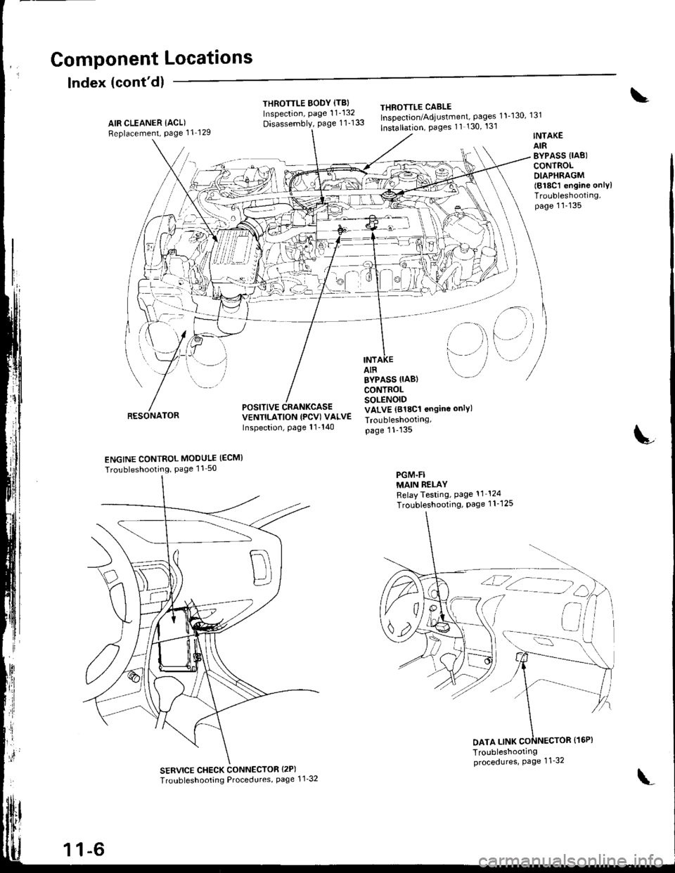
Gomponent Locations
Index (cont'dl
THROTTLE BODY {TBIInspection, page 1 1'132
Disassembly, page 1 1-133
THEOTTLE CABLEInspection/Adjustment, pages 11-130, 131
lnstallation, Pages 11 130' 131AIR CLEANER IACL)Replacement, Page 11 129
RESONATOR
INTAKEAIRBYPASS {IAB)CONTROLDIAPHRAGM(818C1 engine onlylTroubleshooting,page 11-135
i-)
i--- / /
i rl
l'-' i
INTAIR
POSITIVE CRANKCASEVENTILATION (PCV) VALVEInspection, page 11'140
BYPASS IIAB}CONTROLSOLENOIDVALVE (818C1 ongine only)
Troubleshootrng,page 11-135
PGM-FIMAIN RELAYRelayTesting, Page 11 124
Troubleshooting, Page 1 1-1 25
L
ENGINE CONTROL MODULE IECM}
Tro!bleshooting, Page 11 50
SERVICE CHECK CONNECTOR {2P)
Troubleshooting Procedures, page 1 1'32
DATA LINK
1 1-6
\'
Page 227 of 1681
![HONDA INTEGRA 1998 4.G Workshop Manual System Description
System Gonnectors IEngine Compartment]
\
c1G)
c113
c132
cr31 L
UNDER.t{ooDFUSE/RELAYBOX
MAINWIREHARNESS
WIRE HARNESS
11-22 HONDA INTEGRA 1998 4.G Workshop Manual System Description
System Gonnectors IEngine Compartment]
\
c1G)
c113
c132
cr31 L
UNDER.t{ooDFUSE/RELAYBOX
MAINWIREHARNESS
WIRE HARNESS
11-22](/img/13/6069/w960_6069-226.png)
System Description
System Gonnectors IEngine Compartment]
\
c1G)
c113
c132
cr31 L
UNDER.t{ooDFUSE/RELAYBOX
MAINWIREHARNESS
WIRE HARNESS
11-22
Page 231 of 1681
![HONDA INTEGRA 1998 4.G Workshop Manual I
ll
System Description
System Gonnectors [Dash and Floor]
\
ENGINECOMPARTMENTWIREHARNESSPGM.FI MAIN
RELAYOASHBOARD WIREHARNESS
L
.1
:J HONDA INTEGRA 1998 4.G Workshop Manual I
ll
System Description
System Gonnectors [Dash and Floor]
\
ENGINECOMPARTMENTWIREHARNESSPGM.FI MAIN
RELAYOASHBOARD WIREHARNESS
L
.1
:J](/img/13/6069/w960_6069-230.png)
I
ll
System Description
System Gonnectors [Dash and Floor]
\
ENGINECOMPARTMENTWIREHARNESSPGM.FI MAIN
RELAYOASHBOARD WIREHARNESS
L
.1
:J
Page 241 of 1681
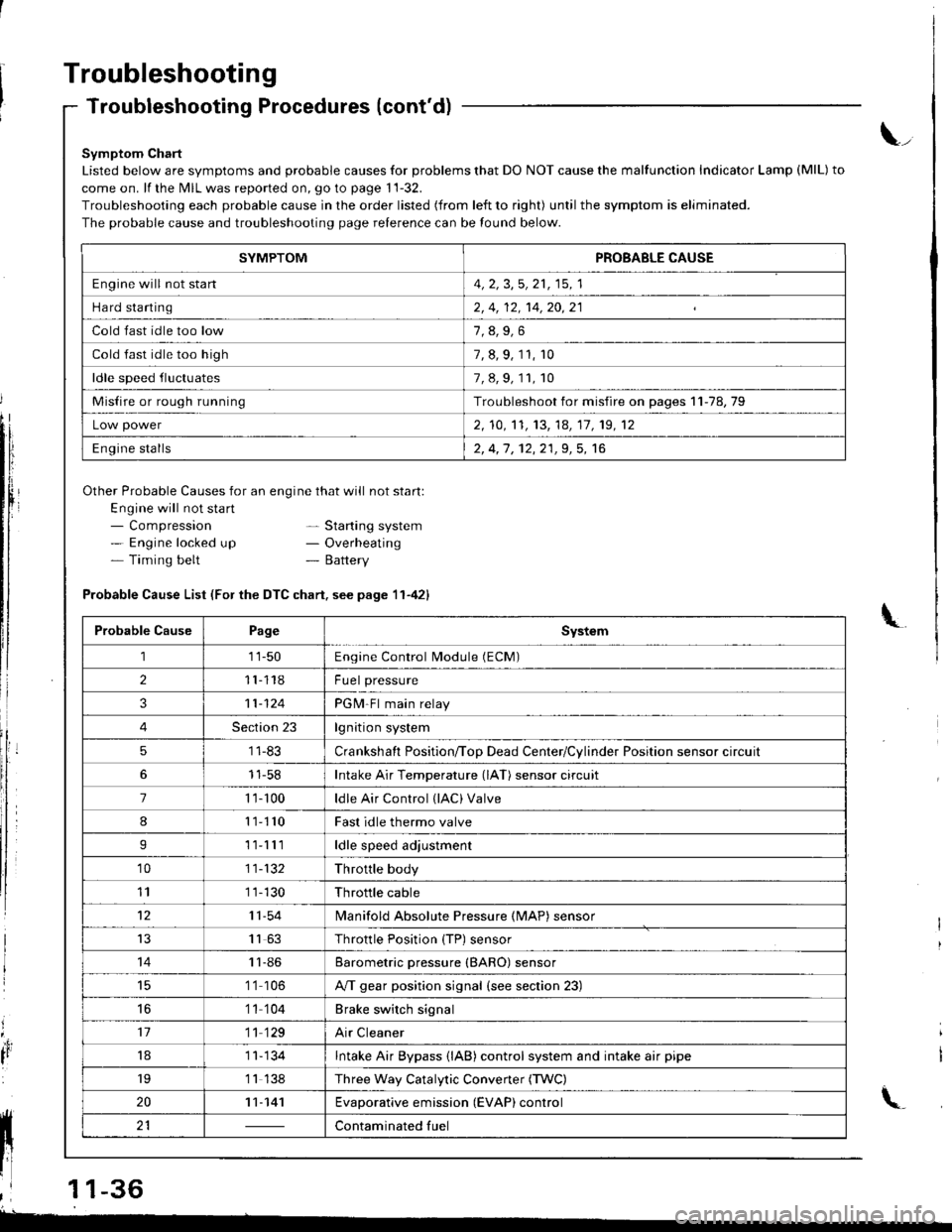
Troubleshooting
Troubleshooting Procedures (cont'd)
Symptom Chart
Listed below are symptoms and probable causes for problems that DO NOT cause the malfunction Indicator Lamp (MlL) to
come on. lf the MIL was reported on, go to page 11-32.
Troubleshooting each probable cause in the order listed (from left to right) until the symptom is eliminated.
The probable cause and troubleshooting page relerence can be found below.
Other Probable Causes for an engine that will not start:
Engine will not sta rt- Compression- Engine locked up- Timing belt
\_
- Starting system- Overheating- Battery
'4,
It
Probable Cause List (For the DTC chart. see page 11-421
Probable CausePageSystem
111-50Engine Control Module (ECM)
211118Fuel pressure
311-124PGM-Fl main relay
4Section 23lgnition system
51 1-83Crankshaft Position/ToD Dead Center/Cylinder Position sensor circuit
11-58Intake Air Temperature (lAT) sensor circuit
71 '�t- 100ldle Air Control (lAC) Valve
811110Fast idle thermo valve
I11lllldle speed adjustment
'1011-132Throttle body
111 1-130Throttle cable
1211-54lvlanifold Absolute Pressure {MAP) sensor
IJ1163Throttle Position {TP) sensor
1411-86Barometric pressure (BARO) sensor
1 '1 106A/T gear position signal {see section 23)
16'1 1 104Brake switch signal
1711 129Air Cleaner
181 1- 134Intake Air Bypass {lAB} control system and intake air pipe
19'1 1 138Three Way Catalytic Convener (TWC)
2011-141Evaporative emission (EVAP) control
21Contaminated fuelll ll 21 | - | cont"-in"t"o tu"
11 l-
I
,l 11-36
-
SYMPTOMPROBABLE CAUSE
Engine will not stan4, 2, 3,5, 21, 15, 1
Hard starting2, 4, 12, 14,20,21
Cold fast idle too low
Cold fast idle too high7, 8, 9, 11, r0
ldle speed fluctuates7,8,9,11,10
Misfire or rough runningTroubleshoot for misfire on pages 11-78,79
Low power2, 10,'t1, 13, 14, 17, 19, 12
Engine stalls2, 4,1 , 12,21,9, 5, 16
Page 253 of 1681
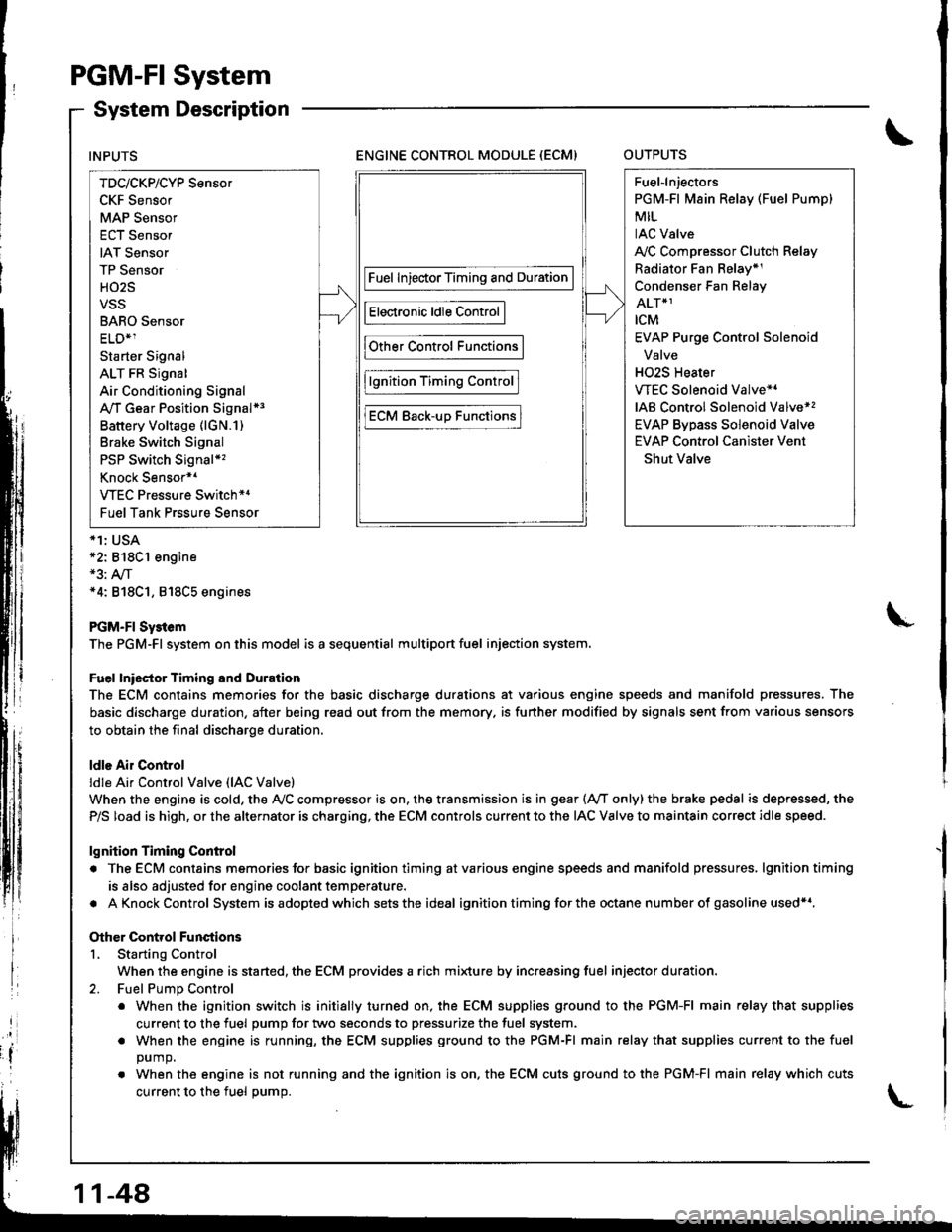
PGM-FI System
System Description
ENGINE CONTROL MODULE (ECM)OUTPUTS
*1: USA*2: 818C1 engine*3: A,/T*4: 818C1, 818C5 engines
PGM-FI Sy3tem
The PGM-Fl system on this model is a sequential multiport fuel injection system.
Fuel lniector Timing and Duration
The ECM contains memories for the basic discharge durations at various engine speeds and manifold pressures. The
basic discharge duration, after being read out from the memory. is further modified by signals sent from various sensors
to obtain the final discharge duration.
ldle Air Control
ldle Ai. Control Valve (lAC Valve)
When the engine is cold, the Ay'C compressor is on. the transmission is in gear (Ay'T only)the brake pedal is depressed, the
P/S load is high, or the alternator is charging, the ECM controls current to the IAC Valve to maintain correct idle speed.
lgnition Timing Control
. The ECM contains memories for basic ignition timing atvarious engine speeds and manifold pressures, lgnitiontiming
is also adjusted for engine coolant temperature.
. AKnockControl System isadoptedwhich sets the ideal ignition timing for the octane n um ber of gasoline used*r,
Other Control Functions
L Starting Control
When the engine is started, the ECM provides a rich mi{ure by increasing fuel injector duration.
2. Fuel PumD Control
. When the ignition switch is initially turned on, the ECM supplies ground to the PGM-FI main relay that supplies
current to the fuel pump for two seconds to pressurize the fuel system.
. When the engine is running, the ECM supplies ground to the PGM-FI main relay that supplies current to the fuel
DUmO.
. When the engine is not running and the ignition is on. the ECM cuts ground to the PGM-FI main relay which cuts
current to the fuel oumo.
INPUTS
TDc/CKP/CYP Sensor
CKF Sensor
MAP Sensor
ECT Sensor
IAT Sensor
TP Sensor
HO2S
VSS
BARO Sensor
ELD*1
Starter Signal
ALT FR Signal
Air Conditioning Signal
A,/T Gear Position Signal*3
Battery Voltage (lGN.1)
Brake Switch Signal
PSP Switch Signal*'�
Knock Sensor*1
VTEC Pressure Switch*4
Fuel Tank Prssure Sensor
Fuel InjectorTiming and Duration
Electronic ldle Control
Other Control Functions
lgnition Timing Control
ECM Back-uD Functions
Fuel-lnjectors
PGM-Fl Main Relay (Fuel Pump)
MIL
IAC Valve
A,/C Compressor Clutch Relay
Radiator Fan Belay*1
Condenser Fan Relay
ALT*1
rcM
EVAP Purge Control Solenoid
Valve
H02S Heater
VTEC Solenoid Valve*'
IAB Control Solenoid Valve*,
EVAP Bypass Solenoid Valve
EVAP Control Canister Vent
Shut Valve
11-48
Page 256 of 1681
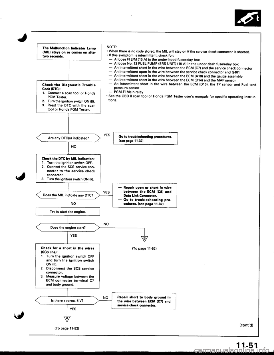
NOTE:. Whon there is no cod6 stored, the MIL willstay on iftho aorvice check conn€ctor is snoned.' lfthis symptom is intermittent. check tor:- A loos6 Fl E/M (15 A) in the undor-hood tuse/relav box- A loose No. 13 FUEL PUMP {SRS UNIT) (15 A) in th6 under-dash fuse/retay box- An intermitt6nt short in the wir€ betwesn the ECM (C7) and th€ sorvice chock conn€qor- An intormittent open in the wire between the sorvice chsck conneclor and G40l- An intermittent short in the wire betwo€n the ECM (A18) and the gaug6 assemDry- An intermittent shon in the wir6 between the ECM (D14) and the MAP sonsor- An intermittent shon in the wire bstween the ECM (Dto), th6 Tp sensor and Fu6l tankpI6SSU16 SOnSOT- PGM-FI Main relay. See th6 OBD ll scan tool or Honda PGM Tester user's manuals for sp6cific operating instruc-!ons.
(To page 11-52)
(cont'd)
Th. M.lfunction Indic.tor LlmplMlll .t!yr on or comlr on ltt .two aaconda.
Ch.ck th! Dirgnoitic tioubl.Cod. IDTC):'1. Connoct a 6can tool or HondaPGM Tester,2. Turn tho ignition switch ON (ll).3. Read tho DTC with the scantool or Honda PGM T6st6r.
Go to trouHorhooting proQduaaa.
koo p.g6 I 1.3:ll
Ch.ct th. DTC by MIL indication:1. Turn th€ ignition switch OFF.2. Connect the SCS seNic€ con-n€ctor to the sorvico checkconnoctor,3. Turn the ignition s1\,itch ON (ll).
Rapair opan or ahort in wirabotw..n thg ECM lCSl .ndData Llnk Conncctor.Go lo troublcrhootlng pro-c.dur.3. {.co pag. 11-32)
Do.s th6 MIL indicate anv DTC?
Try to start tho engine.
Chack lor r 3hort in th. wlr.3lsqg lln.):1. Turn the ignition switch OFFand turn the ignition switchoN { },2. Disconnect th6 SCS serviceconnector,3. M€a6urg voltaOe between theECM connoctor torminal C7and body ground.
Rapah 3hort to body ground inlh. wir. b.lw..n ECM lCTl .ndacwica chack connactor.
ls ther6 approx. 5 V?
\{,
(To page 11-52)
11-51
Page 258 of 1681
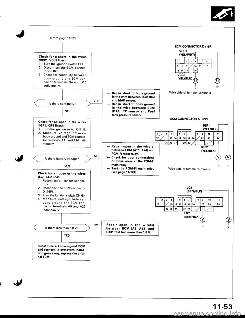
{From page 11 52)
Chock lor a shon in lhe wi.asiVCC1. VCC2lin$l:1. Turn the ignition switch OFF-2. Disconnect the ECM connec,tor D (16P).
3. Check lor continuity betweenbody ground and ECM con-nector terminals D4 and D10individually.
- Repair short to body groundin tho wire between ECM {D4land MAP 3enso..- Rep.ir short to body groundin the wire between ECMlD10l, TP sensor and Fueltank pa6ssure sanso..
Chock lor an op€n in the wire3{lGP1.lGP2lines):1. Turn the ignition switch ON (ll).2, Measure voltage betweenbody ground and ECM connec-torterminals A'11 and A24 indi-vadually.- R6pe;r open in the wire{slbetween ECM 1A11, A24l andPGM-FI main .elay.- Check for poor connectionsor loose wi.es at the PGM-FImain relay.- Test tho PGM-FI main ral.v(see page 11-124).Check for an open in the wires(LG1, LG2line3l:1. Reconnect all sensor connec-tors.2. Reconnect the ECM connectorD (16P).
3. Turn the ignition switch ON (ll).4- M easu re voltage betweenbody ground and ECM connector terminals A9 and A22individually.
Repai. open in the wir€ls)bctween ECM {A9, A22l .ndG101 ihet had more then 1.0 V.
ls there lessthan 1.0 V?
Substitute , known-good ECMand rechock. f symptom/indica-tion goes away, roplac6 the odgi-n3l ECM.
Wire side of female terminals
ECM CONNECTOR A I32P)
a,
Wire side of female terminals
LGl
1 1-53
Page 301 of 1681
ldle Control System
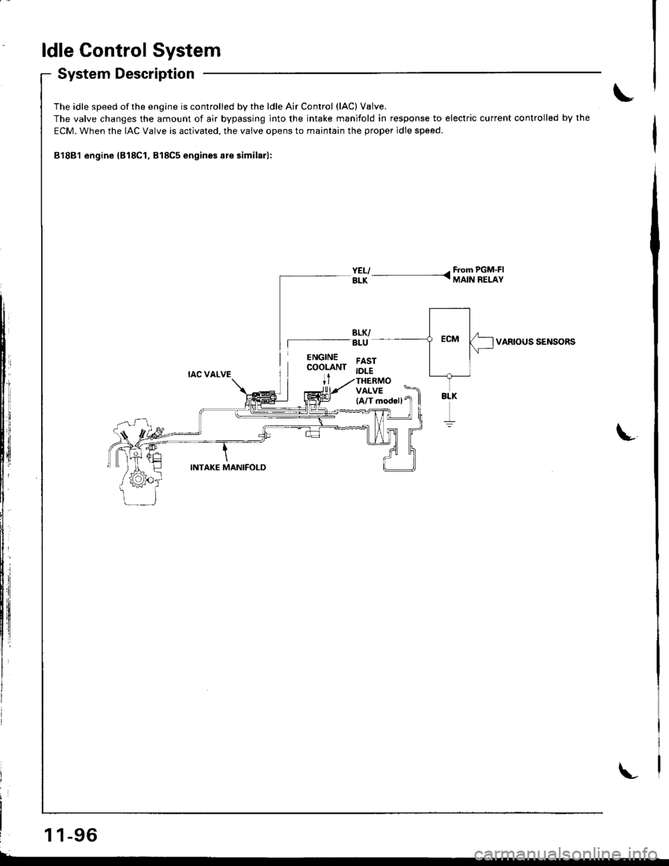
System Description
The idle speed of the engine is controlled by the ldle Air Control (lAC) V8lve.
The valve changes the amount of air bypassing into the intake manifold in response to electric current controlled by the
ECM. When the IAC Valve is activated. the valve opens to maintain the proper idle speed.
81881 engine {B18Cl, B18C5 engines are similarl:
YELI - F.om PGM'FIBLK - MAIN RELAY
VARIOUS SENSORS
L
1 1-96
Page 310 of 1681
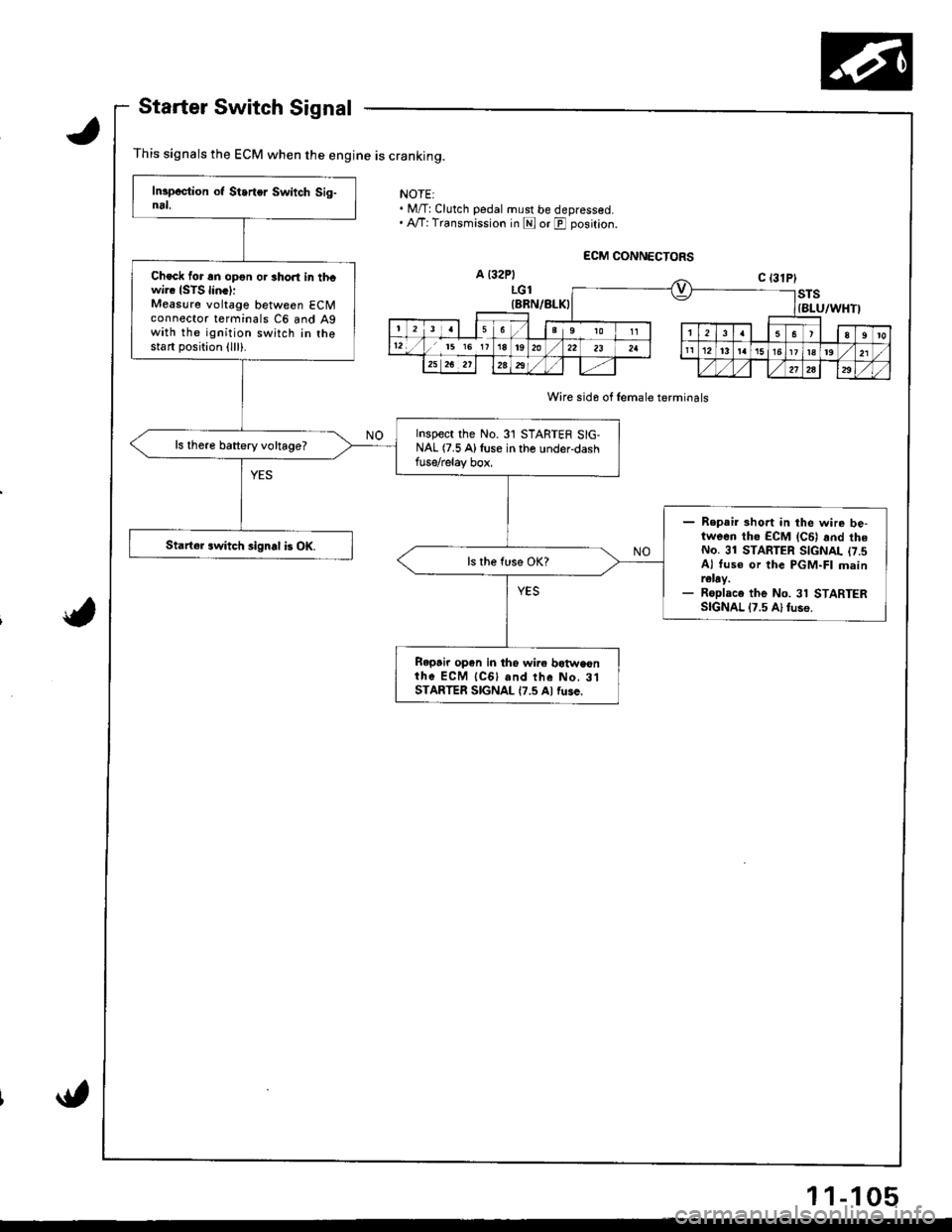
Starter Switch Signal
This signals the ECM when the engine is cranking.
NOTEI. M/T:Clutch pedal must be depressed.. A,/T: Transmission in E or E position.
Wire sida of female terminals
Check for an opon or short in thcwi.. ISTS lin.l:Measure voltage between ECMconnector terminals C6 and Agwith the ignition switch in thostart position (lll).
Inspect the No.31 STARTER SIG-NAL (7.5 Alluse in the under-dashfuse/relay box,
ls there battery voltage?
- Repair 3hort in the wire be-tween tho ECM lc6l rnd theNo. 31 STARTER SIGNAL (7.sAl tus€ or the PGM-FI mainr€lay.- Roplace the No. 31 STARTERSIGNAL 17.5 Al fuso.
Starter switch signal b OK.
Ropair open in tho wire botwaonih6 ECM {CGl and the No, 3lSTARTER SIGNAL {7.5 Al fuse.
11-105
Page 323 of 1681
The fuel supply system co
high pressure fuel pump, t
fuel pressure regulator. f
damper, and fuel delivery i
delivers pressure-regulated
cuts the luel delivery when
Fuel Supply System
System Description
consists of a fuel tank, in-tank
r, PGM-Fl main relay, fueffilter,
. fuel injectors, fuel pulsation
y and return lines. This system
ed fuel to the fuel injectors and
rn thq engine is not running.
Fuel Pressure
Relieving
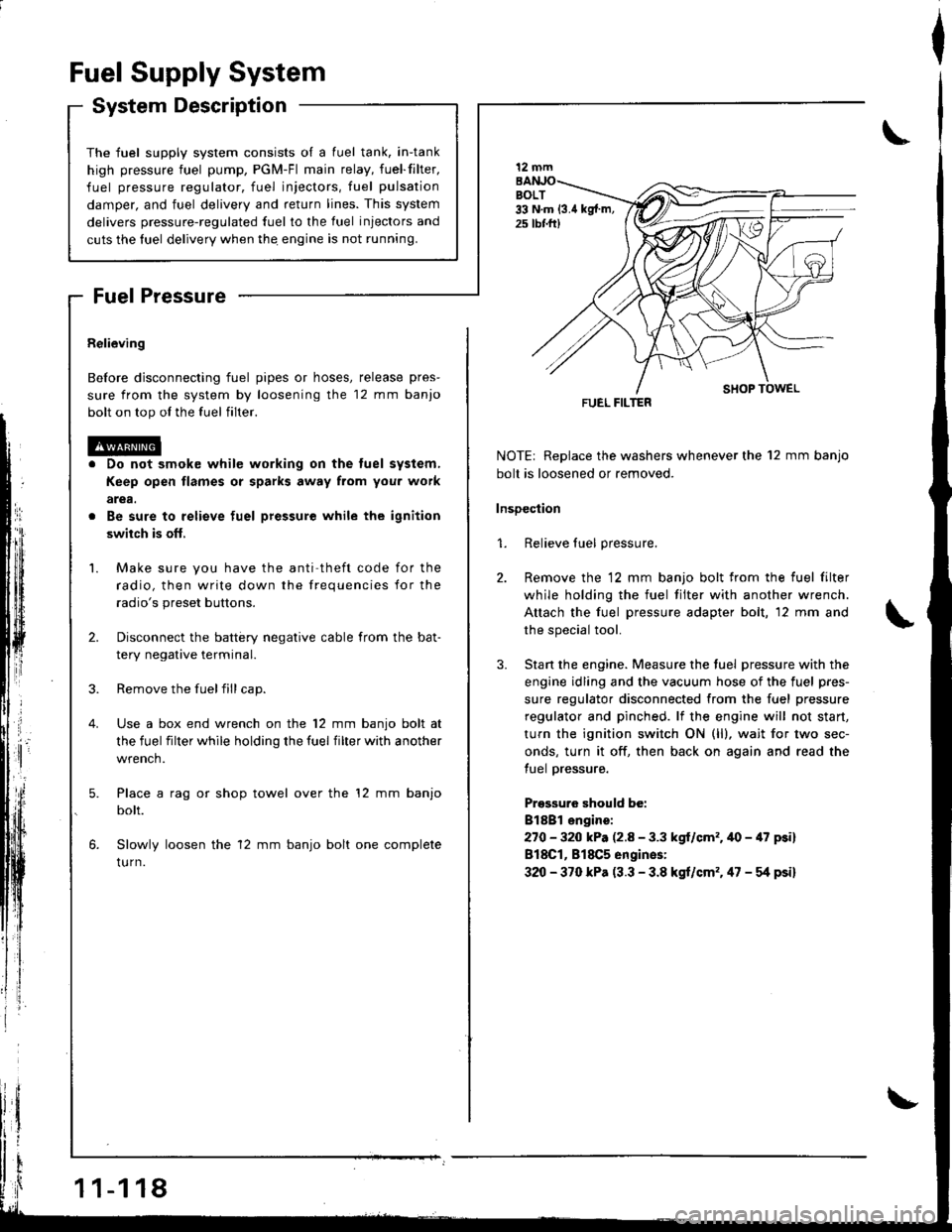
Before disconnecting fuel pipes or hoses, release pres-
sure from the system by loosening the 12 mm banjo
bolt on top ol the fuel filter.
Do not smok€ while working on the tuel system,
Keep open flames or sparks away from you. work
arga.
Be sure to relieve fuel pressure while the ignition
swiich is ofl,
Make sure you have the anti theft code for the
radio, then write down the frequencies for the
radio's preset buttons.
Disconnect the battery negative cable from the bat-
tery negative terminal.
Remove the fuelfill cap.
Use a box end wrench on the 12 mm banjo bolt at
the fuel filter while holding the fuel filter with another
wrench.
Place a rag or shop towel over the '12 mm banjo
bolt.
Slowly loosen the 12 mm banjo bolt one complete
tu rn.
1 1-1 18
I
NOTE| Replace the washers whenever the 12 mm banjo
bolt is loosened or removed.
lnsDection
1. Relieve fuel pressure.
2. Remove the 12 mm banjo bolt from the fuel filter
while holding the fuel tilter with another wrench.
Attach the fuel pressure adapter bolt, 12 mm and
the special tool.
3. Stan the engine. Measure the tuel pressure with the
engine idling and the vacuum hose of the fuel pres-
sure regulator disconnected from the fuel pressure
regulator and pinched. lf the engine will not start,
turn the ignition switch ON (ll), wait for two sec-
onds, turn it off, then back on again and read the
tuel pressure.
Pressuro should be:
Bl8Bl engire:
270 - 320 kP. (2.8 - 3.3 kgl/cm'�.40 - 47 psi)
818C1, 818C5 engines:
320 - 370 kPa (3.3 - 3.8 kgt/cm'�. 47 - g psi)
12 mm
FUEL FILTER