engine HONDA INTEGRA 1998 4.G Workshop Manual
[x] Cancel search | Manufacturer: HONDA, Model Year: 1998, Model line: INTEGRA, Model: HONDA INTEGRA 1998 4.GPages: 1681, PDF Size: 54.22 MB
Page 1078 of 1681
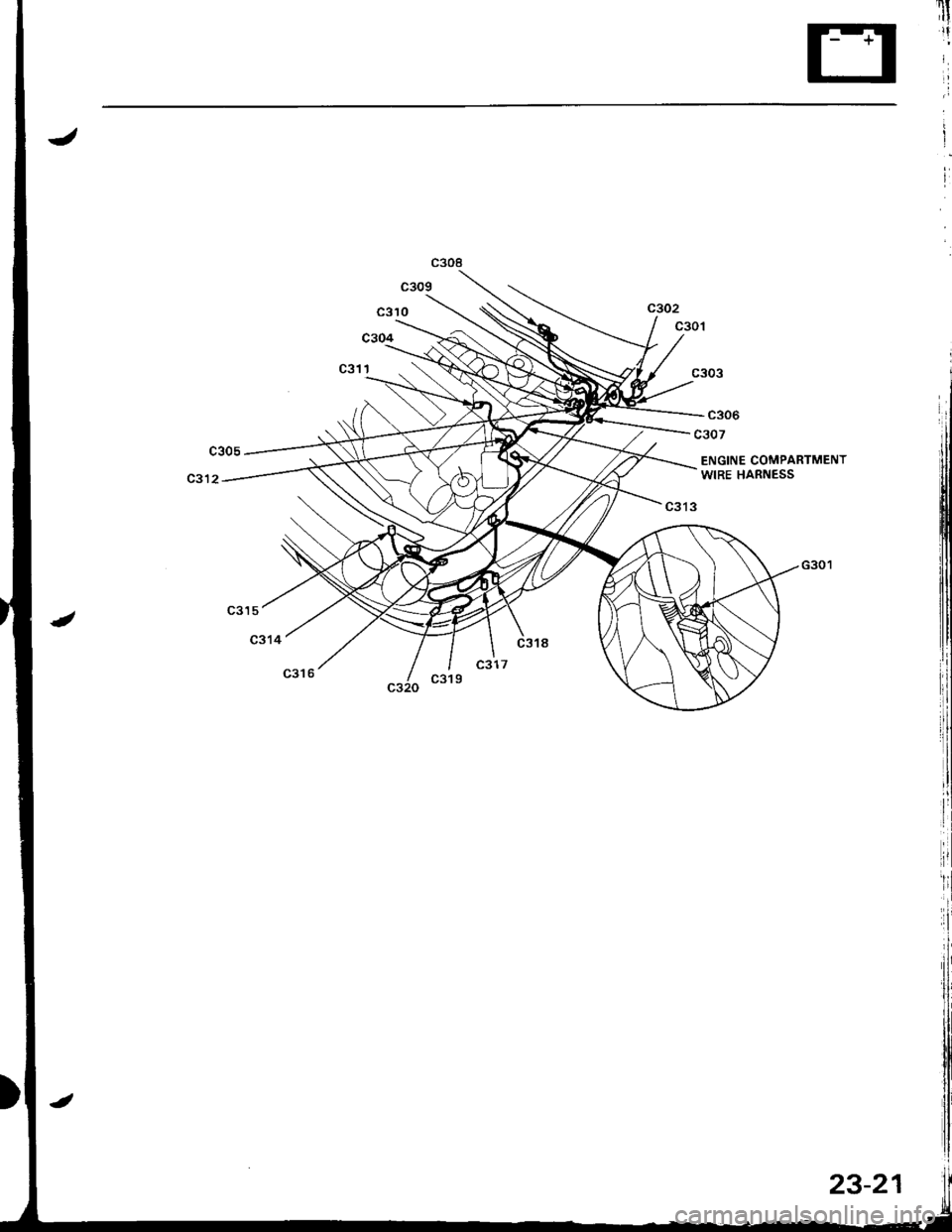
c306
c307
ENGINE COMPARTMENTWIRE HARNESS
G301
Page 1079 of 1681
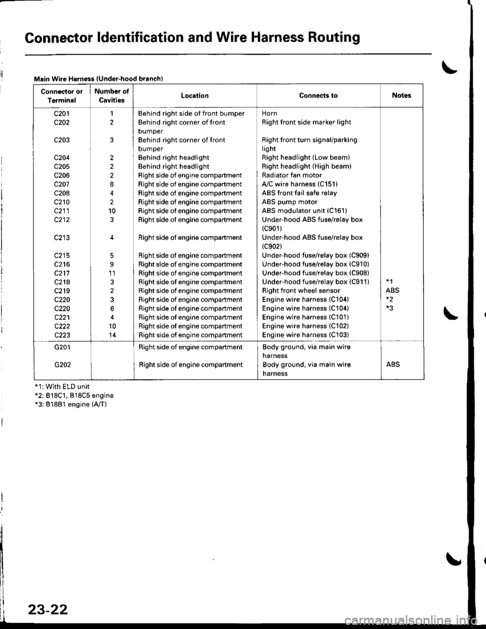
Connector ldentification and Wire Harness Routing
Main Wire Harness (Under-hood branchl
Conneqtor or
Terminal
Number ol
CavitiesLocationConnests toNotes
c201
c202
c203
c204
c205
c206
c207
c208
c210
c211
c213
c215
c216
c211
c218
c2r 9
c220
c220
c221
c222
c223
1
2
2
2
2
8
2
10
5
9'11
3
2
3
6
10
14
Behind right side of front bumper
Behind right corner of front
bumper
Behind right corner of front
DUmper
Behind right headlight
Behind right headlight
Right side of engine compartment
Right side of engine compartment
Right side of engine compartment
Right side of engine compartment
Right side of engine compartment
Right side of engine compartment
Right side ot engine compartment
Right side of engine compartment
Right side of engine compartment
Right side of engine compartment
Right side of engine compartment
Right side of engine compartment
Right side of engine compartment
Right side oI engine companment
Right side ot engine compartment
Right side ot engine compartment
Right side of engine compartment
norn
Right front side marker light
Right front turn signaUparking
lig ht
Right headlight (Low beam)
Right headlight (High beam)
Radiator lan motor
A"/C wire harness (C151)
ABS front fail safe relay
ABS pump motor
ABS modulator unit (C151)
Under-hood ABS fuse/relay box(c901)
Under-hood ABS fuse/relay box
{c902}
Under-hood fuse/relay box (C909)
Under-hood fuse/relay box (C910)
Underhood fuse/relay box (C908)
Under-hood fuse/relay box (C911)
Right front wheel sensor
Engine wire harness {C104)
Engine wire harness (C104)
Engine wire harness (C101)
Engine wire harness {C102)
Engine wire harness (C103)
*1
ABS
G201
G202
Right side of engine compartment
Right side of engine compartment
Body ground. via main wire
narness
Body ground, via main wire
harness
ABS
+1:With ELD unit*2: B18C't, 818C5 engine*3: 81881 engine (A,/T)
23-22
Page 1081 of 1681
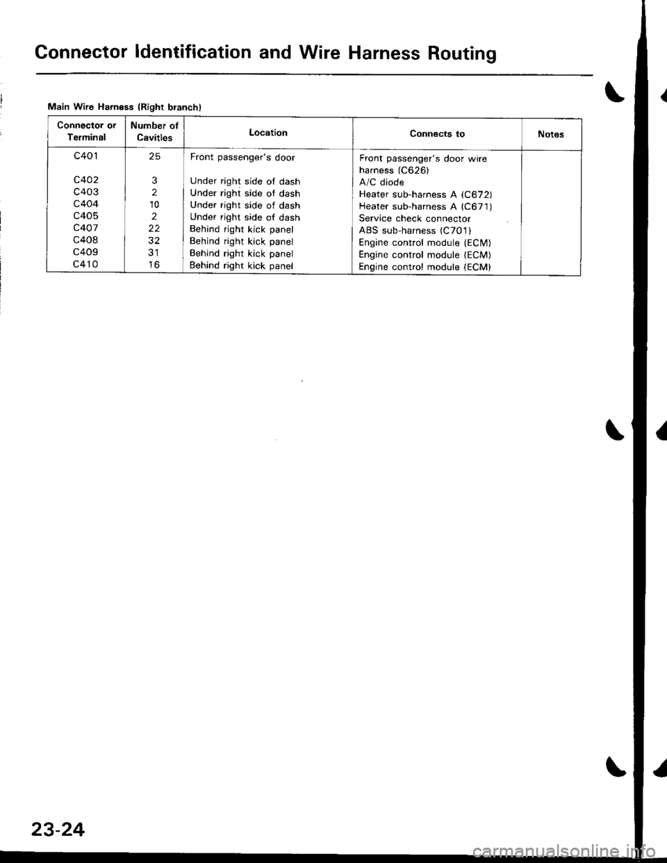
Gonnector ldentification and Wire Harness Routing
Main Wire Harness {Right branchl
Connector or
Terminal
Number of
CavitiesLocationConnects toNot6s
c401
c402
c403
c404
c405
c407
c408
c409
c410
25
3
2
10
2
22
32
lo
Front passenger's door
Under right side of dash
Under right side ot dash
Under right side of dash
Under right side of dash
Behind right kick panel
Behind right kick panel
Behind right kick panel
Eehind right kick panel
Front passenger's door wire
harness (C626)
A/C diode
Heater sub-harness A (C672)
Heater sub-harness A (C671)
Service check connector
ABS sub-harness (C7O l)
Engine control module {ECfM)Engine control module lECM)Engine contfol module (ECM)
23-24
Page 1083 of 1681
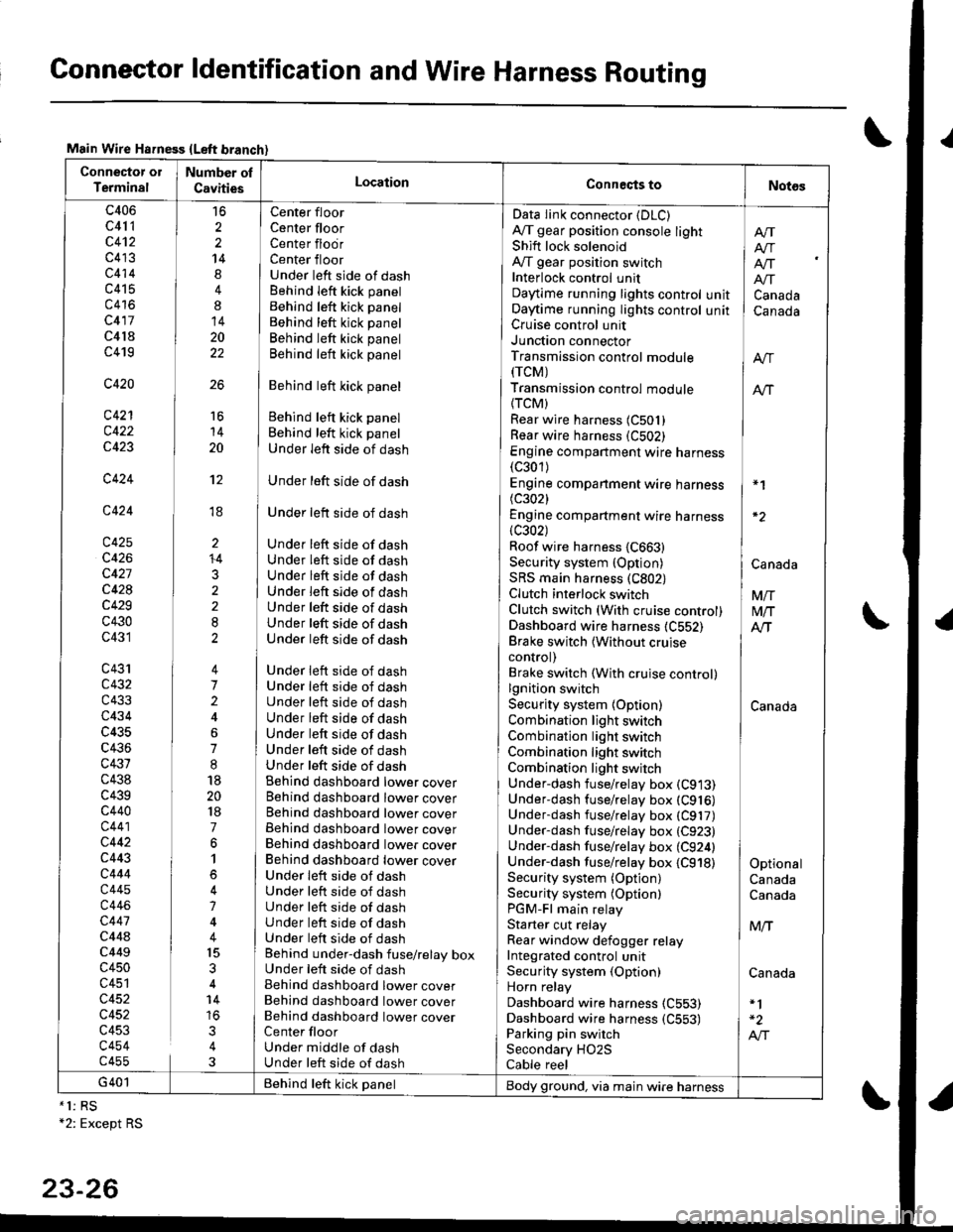
Connector ldentification and Wire Harness Routing
Main Wire Hsfness {Left branch}
Connector ol
TerminalNumber ol
CavitiesLocationConneqts toNot6s
c406
c41 1
c4't2
c413
c414
c415
c416
c417
c4l8
c419
c420
c421
c422
c423
c424
c424
c425
c426
c427
c428
c429
c430
c431
c43'rc432
c433
c434
c435
c436
c431
c438
c439c440
c441
c442
c443
c444
c445
c446
c447
c44ac449
c450
c451
c452
c452
c453
c454c455
16
2
2
14
4
8
14
20
22
26
Center floor
Center floorCenter flodrCenter floorUnder left side of dashBehind Ieft kick panel
Behind left kick panel
Behind left kick panel
Behind left kick panel
Behind left kick panel
Behind left kick panel
Behind left kick panel
Behind left kick panel
Under left side of dash
Under left side of dash
Under left side of dash
Under left side of dashUnder left side of dashUnder left side of dashUnder left side of dashUnder left side of dashUnder left side of dashUnder left side of dash
Under left side of dashUnder left side of dashUnder left side of dashUnder left side of dashUnder left side of dashUnder left side of dashUnder left side of dashBehind dashboard lower coverBehind dashboard lower coverBehind dashboard lower coverBehind dashboard lower coverBehind dashboard lower coverBehind dashboard lower coverUnder leit side of dashUnder left side of dashUnder left side of dashUnder left side of dashUnder left side of dashBehind under-dash fuse/relay boxUnder left side of dashBehind dashboard lower coverBehind dashboard lower coverBehind dashboard lower coverCenter floorUnder middle of dashUnder left side of dash
Data Iink connector (DLC)
A,/T gear position console lightShift lock solenoidAy'T gear position switchInterlock control unitDaytime running lights controlOaytime running lights controlCruise control unitJunction connectorTransmission control module(rcM)
Transmission control module
{TCM)Rear wire harness (C501)
Rear wire harness (C502)
Engine compartment wire harness(c301)
Engine companment wire harness I *1
(c3021 IEngine compartment wire harness(c302) lRoof wire harness {C663} |Security system {Option) | CanaAaSRS main harness (C802) |Clutch interlock switch I VnClutch switch (With cruise control) M/TDashboard wire harness (C552) AlTBrake switch lwithout cruise Icontrol) |Brake switch (With cruise control)lgnition switch ISecurity system {Option) CanadaCombination light switch /Combination light switch ICombination light switchCombination light switchUnder-dash fuse/relay box (C913)
Under-dash fuse/relay box (C916)
Underdash fuse/relay box (C917)
Under-dash fuse/relay box (C923)
Under-dash fuse/relay box (C924) |Under-dash fuse/relay box {C918) I OptionalSecurity system (Option) CanadaSecurity system (Optionl CanadaPGM-Fl main relayStarter cut relay ] M,.fRear window defogger relay IIntegrated control unitSecurity system (Option) CanadaHorn relay
Dashboard wire harness (C553)
Dashboard wire harness {C553) | -2
Parking pin switch I A,"ISecondary HO2S
Cable reel
Afi
I Atr
lf[
unit ] Canadaunit I Canada
16
14
20
't2
ti
I'
li
ll
li
+4
3
G401 Behind teft kick panelBody ground, via main wire harness*1: RS+2: Except RS
23-26
Page 1118 of 1681
l'
i'l
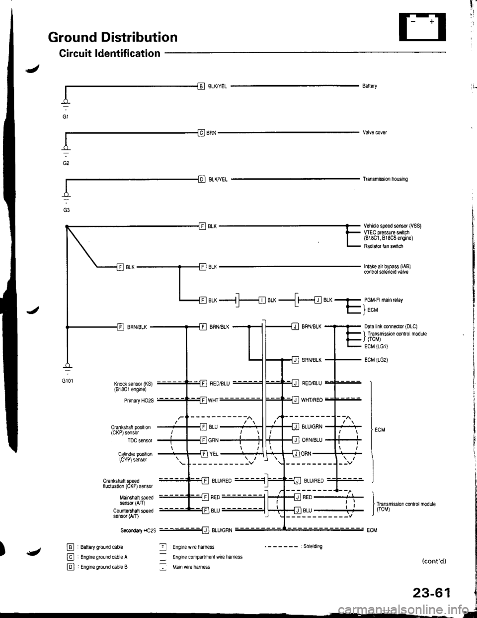
Ground Distribution
Circuit ldentification
I-l
Ballery
Transmi9slon housing
Intake air bypass (lAB
Vehicle speed sensor (VSS)WEC flessuae $ilch(818O1,818C5 engine)
Radialor lan sMch
Cranlshatl posrton(CKP)sensor
luu sensor
Cllinder positionICYP) sensor
d:
aLx -{ f---{eLx-.ll{el<- PGM-F:main retay
f- | ec"
Dala link clnneclor (DLC)
I lransmissDn cor ro modlleJ (TCM)
ECM (LG1)
ECM (LGz)
GOl
--------1--l\
8LU/GRN
ORN/BLU
vYflt/tlEU--
ORN
---------J--v
"J)
-{ neo ----+J-
------------l
.i
rr"n.rit ion *t,o,.oarb
J ficM)r,u----4
-------:Shielding
_ Engife conparlmenl wire harness
: Main wi€ harness(cont'd)
23-61
Crankshall speedf luclualion (CKF) sensor
Mainshall speeds6n5o. (a'I)
Counl$shafi speedsensor (rVT)
S€condtY f1c2s
E : Batlsry ground cable
El : Enginegrowd cabe A
E I Engineground cable B
_J] ELU/UHN
3 Enginewire haness
ELU/hEU_.1
I
Page 1134 of 1681
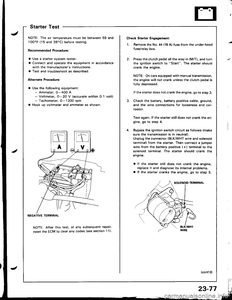
Ch6ck Starter Engag€mont;
1. Remove the No. 44 (15 A) fuse from the under-hood
fuse/relay box,
Press the clutch pedal all the way in (M/T), and turn
the ignition switch to "St8rt". The staner should
crank the engine,
NOTE: On cars equipped with manual transmission,
the engine will not crank unless the clutch pedal is
fully depressed.
lf the starter does not crank the engine, go to step 3.
Check the battery, battery positive cable, ground,
and the wire connections for looseness and cor-
rosion.
Test again. lf the stsner stilldoes not crank the en-
gine, go to step 4.
Bypass the ignition switch circuit as follows {make
sure the transmission is in neutral)
Unplug the connector (BLKMHT wire and solenoid
terminal) trom the staner. Then connect a jumper
wire from the batterv positive (+ ) terminal to the
solenoid terminal. The starter should crank the
engine.
a It the stsrter still does not crank the engine,
replace it and diagnose its internal problems,
a lf the starter cranks the engine. go to step 5.
(cont'd)
4.
NOTE: The air temperature must be between 59 and
100oF {15 and 38'C) betore testing.
Recommended Procedure:
a Use a starter system tester.
a Connect and operate the equipment in accordance
with the manufacturer's instructions.
a Test and troubleshoot as described.
Alternate Procodure:
a Use the following equipment;- Ammeter, O-400 A- Voltmeter. O-20 V (accurate within O,1 volt)- Tachometer, O- 1 2OO rpm
a Hook up voltmeter and ammeter as shown.
NEGATIVE TERMINAL
NOTE: Atter this test, or any subsequent repalr,
reset the ECM to clear any codes (see section 1 1).
StartelTest
23-77
Page 1135 of 1681
Starting System
Starter Test (cont'dl
Check Cranking rpmr
Engine speed during cranking should be above 1OO rpm.
lJ speed is too low, check for:
a Loose batlery or starter terminals
a Excessively worn starter brushes
a Open circuit in commutator segments
a Dirty or damaged helical spline or drive gear
a Defective drive gear overrunning clutch
Check Starter Disengagement:
Press the clutch pedal all the way in (M/T), turn rhe igni
tion switch to "lll" and release to "11".
The starter drive gear should disengage from the flywheel
or torque converter ring gear when you release the key.
It the drive gear hangs up on the flywheel or torque con-
verter ring gear, check for:
a Solenoid plunger and switch mallunction
a Dirty drive gear assembly or damaged overrunning
clutch
5. Check for an open in the BLK/WHT wire circuit be
tween the starter and ignition switch, and con-
necrors,
6. Check the ignition switch (see page 23-71).
7. On cars with automatic transmission, check the A/Tgear position switch (neutral position switch) and
connector. On cars with manualtransmission, check
the starter cut relay, clutch interlock switch, and
connectors.
NOTE: Check the No. 42 (40 A) fuse in the under,hoodfuse/relay box for the starter cut relay.
Check Jor Wear and Damage:
The starter should crank the engine smoothly and stead,ily. lf the starter engages, but cranks the engine errati
cally, remove it. Inspect the starter, drive gear, andllywheel or torque converter ring gear lor damage.
a Check the drive gear overrunning clutch for binding
or slipping when the armature is rotated with the drivegear held. Replace the gears i{ damaged.
Check CJanking Voltage and Current Draw:
Cranking voltage should be no less than 8.O volts.
Current draw should be no more than * amperes.* 1.2 kW: 27O A
1 .4 kW: 360 A
It cranking voltage is too low, or current draw too high,check for:
a Dead or low charged batterya Open circuit in starter armature commutator segmentsa Starter armalure dragging
a Shorted armature windinga Excessive drag in engine
Page 1137 of 1681
Starting System
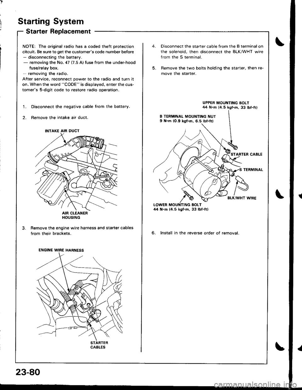
Starter Replacement
NOTE: The original radio has a coded theft protection
citcuit. Be sure to get the customer's code number before- disconnecting the battery.- removing the No. 47 {7.5 A) fuse from the under-hood
fuse/rslav box.- removing the radio.
After service, reconnect power to the radio and turn it
on. When the word "CODE" is displayed. enter the cus-
tomer's 5-digit code to restore radio operation.
Disconnect the negative cable trom the battery.
Remove the intake air duct.
AIR CLEANERHOUSING
R€move the engine wire harness and starter cables
from their brackets.
1.
3.
INTAKE AIR DUCT
ENGINE WIRE HARNESS
CABLES
23-80
5.
Disconnect the starter cable from the B terminal on
rhe solenoid, then disconnect the BLK/WHT wire
from the S terminal.
Remove the two bolts holding the starter, then re-
move the starter.
UPPER MOUNTING BOLT44 N.m (4.5 kgf.m, 33 lbt.fr)
STARTER CABLE
TERMINAL
BLK/WHT WIRE
6. Install in the reverse order of removal.
Page 1155 of 1681
lgnition System
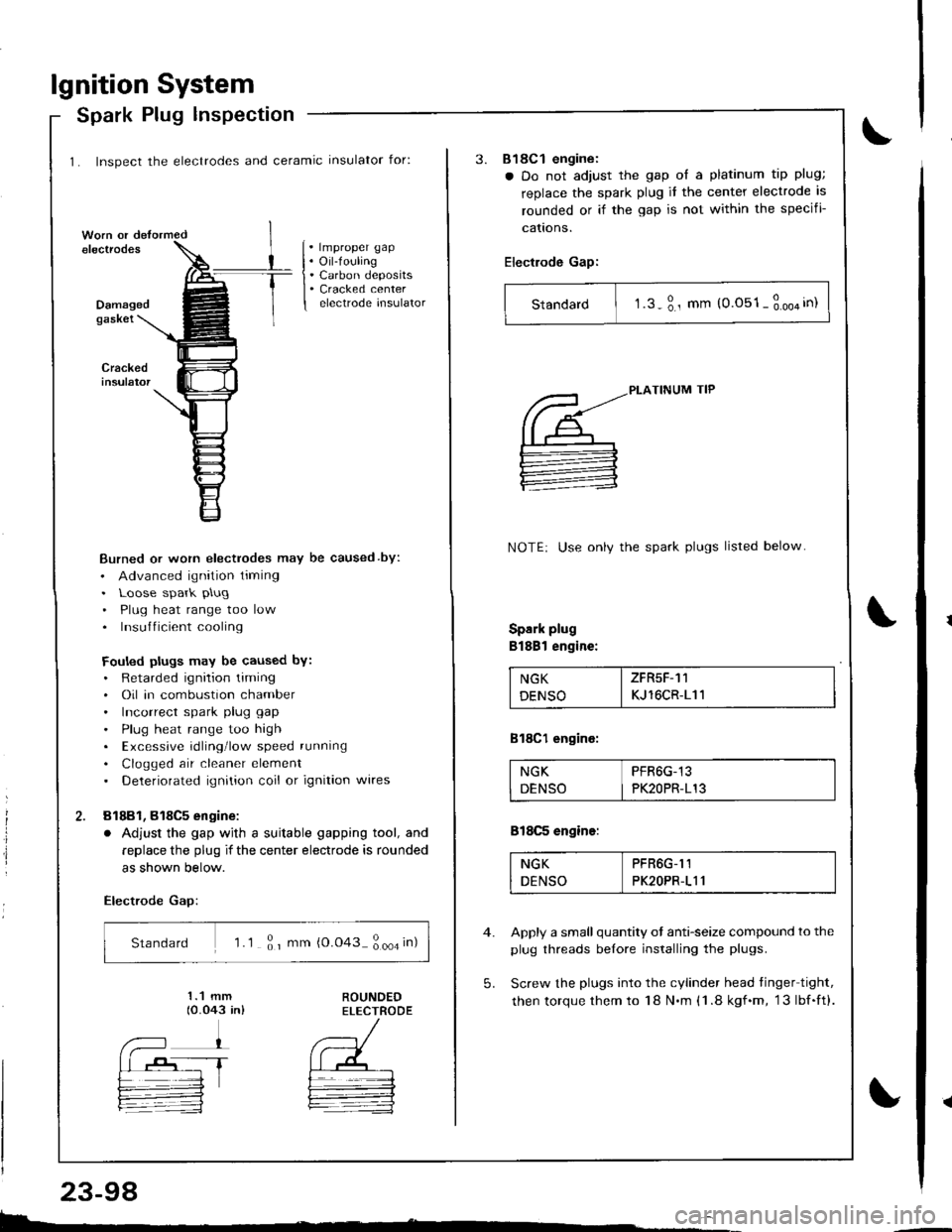
1. Inspect the electrodes and ceramic insulator for:
Spark Plug lnspection
. lmproper gap. Oil-fouling. Carbon deposits. Cracked centerelectrode insulatorDamagedgaskei
Burned or worn electrodes may be caused by:
. Advanced ignition timing. Loose spark plug
. Plug heat range too low. Insufficient cooling
Fouled plugs may be caused bY:. Retarded ignition liming. Oil in combustion chamber. Incorrect spark plug gap
. Plug heat range too high. Excessive rdling'low speed running
. Clogged air cleaner element. Deteriorated ignition coil or ignition wires
81881, 818C5 engine:
. Adjust the gap wjth a suitable gapping tool, and
replace the plug if the center electrode is rounded
as shown below.
Electrode Gap:
Standard 'l .1 ; r mm {0.043 ; ooa in)
E.
23-98
3.818C1 engine:
a Do not adjust the gap ol a platinum tip plug;
replace the spark plug it the center electrode is
rounded or if the gap is not within the specifi-
cattons.
Electrode Gap:
Standard I t.s-3., mm (0.051-3.oo4in)
5.
PLATINUM TIP
NOTE: Use onlv the spark plugs listed below
Spark plug
Bl88l engine:
NGK I ZFR5F-11
DENSO I KJ 16CR-111
818C1 engine:
NGK PFR6G-13
DENSO I PK2OPR-113
818C5 engine:
NGK PFR6G-I1
DENSO PK2OPR-111
Apply a small quantity ot anti-seize compound to the
plug threads belore installing the plugs.
Screw the plugs into the cylinder head tinger tight,
then torque them to 18 N.m (1 .8 kgf.m, 13lbf.ft).
Page 1159 of 1681
Charging System
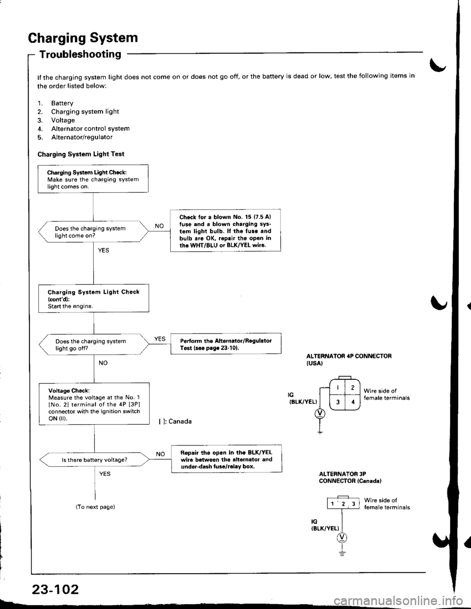
Troubleshooting
It the charging system light does not come on or does not go off, or the battery is dead or low, test the following items in
the order listed below:
1. Battery
2. Charging system light
3. Voltage
4. Alternator control system
5. Alternator/regulator
Charging System Light Test
ALTERNATOR'P CONNECTORIUSAI
IGIBLK/YEL)
Wire side offemale terminals
Wire side offemale terminals
ALTERNATOR 3PCONNECTOR lCanadal
Charging System Light Check:Make sure the charging systemlight comes on.
Ch€ck tor a blown No. 15 (7.5 A)
tuse and . blown charging sys-
tem light bulb. ll the fuse andbulb are OK, .eptir tho open inlhe WHT/BLU or BLK/YEL wire.
Does the charging systemlight come on?
Ch.rging System Light Check(cont'd):
Start the engine.
Pertorm the Ahernator/RegulstolTest (s€. prge 23-101,Does the charging systemlight go off?
Voltago Check:Measure the voltage at the No. 1
lNo. 2l terminal of the 4P [3P]connector with tho ignition switchoN {lr).
Repair tho open in ih€ 8LK/YELwir6 betweon the alte]nator andundor-dash lure/reley box.
I4
L-*
23-102