engine HONDA INTEGRA 1998 4.G Workshop Manual
[x] Cancel search | Manufacturer: HONDA, Model Year: 1998, Model line: INTEGRA, Model: HONDA INTEGRA 1998 4.GPages: 1681, PDF Size: 54.22 MB
Page 995 of 1681
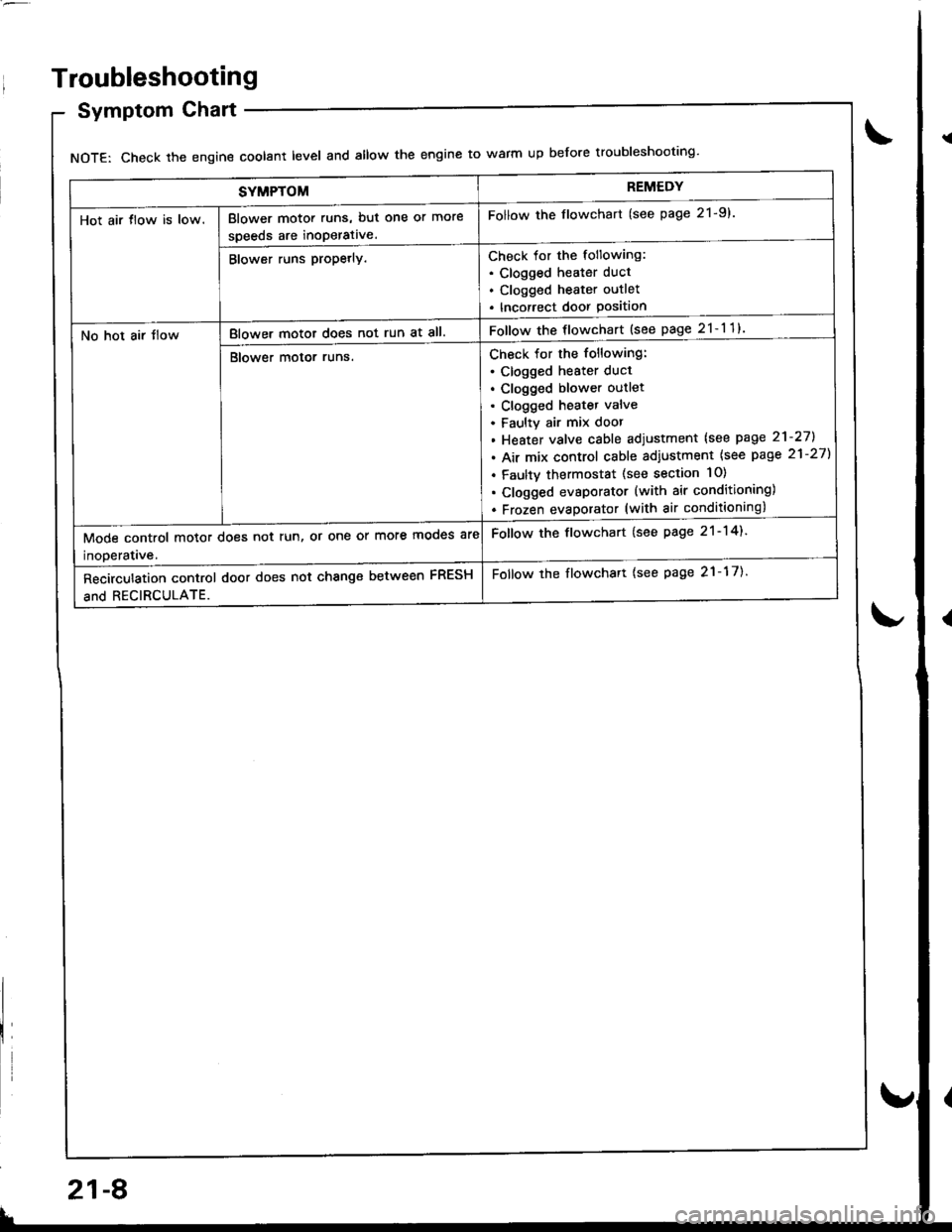
SYMPTOMREMEDY
Hot air tlow is low.Blower motor runs, but one or more
speeds are inoperative.
Follow the flowchart (see page 21-9).
Blower runs propetly.Check for the following:. Clogged heater duct
. Clogged heater outlet
. Incorrect door Position
No hot air tlowBlower motor does not run at all.Follow the flowchart {see page 21-11}
Blower motor runs.Check for the following:
. clogged heater duct
. Clogged blower outlet. Clogged heatet valve
. Faultv air mix door
. Heater valve cable adjustment lsee page 21-27].
. Air mix control cable adiustment {see page 21-27)
. Faulty thermostat (see section 10)
. Clogged evsporator (with air conditioning)
. Frozen evaDorator (with air conditioning)
Mode control motor does not run, or one or more mooes are
inoDeratave.
Follow the flowchart (see page 21-14).
Recirculation control door does not change between FRESH
and RECIRCULATE.
Follow the flowchart {see page 21-17).
Troubleshooting
Symptom Chart
NOTE: Check the engin€ coolant level and allow the engine to warm up before troubleshooting'
21-8
v
Page 1009 of 1681
Heater Unit
Replacement
SRS components are located in this area. Review the
SRS component locatio.s, precautions, and procedures
in the SRS section (23) before performing repairs or ser-
vtce.
1. When the engine is cool, drain the engine coolant
from the radiator (see section 1O).
@ oo not remove the radiator cap when
the engine is hot; the engine coolant is undol
prsssure and could sevdely scald you.
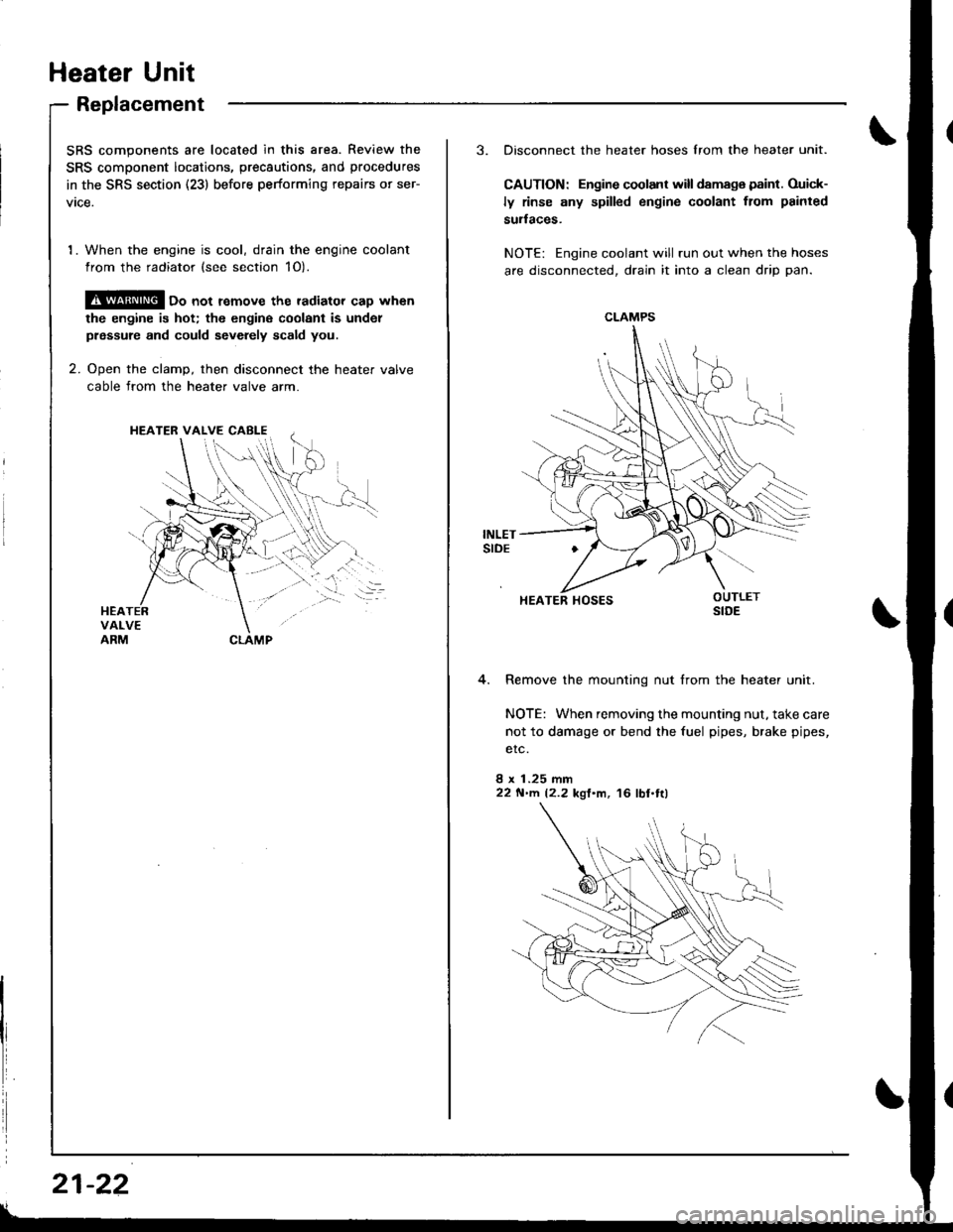
2. Ooen the clamD, then disconnect the heater valve
cable from the heater valve arm.
HEATER VALVE CABI-E
I
i
21-22
3. Disconnect the heater hoses lrom the heater unit.
CAUTION: Engine coolant will damaga paint. Ouick-
ly rinse any spilled engine coolant from painted
sudaces.
NOTE: Engine coolant will run out when the hoses
are disconnected, drain it into a clean drip pan.
4. Remove the mounting nut from the heater unit.
NOTE: When removing the mounting nut, take care
not to damage or bend the fuel pipes, brake pipes,
etc.
8 x 1.25 mm22 N'llt. 12.2 kgl'm, 16 lbl.tl)
CLAMPS
HEATER HOSES
Page 1010 of 1681
.J
5.
6.
7.
8.
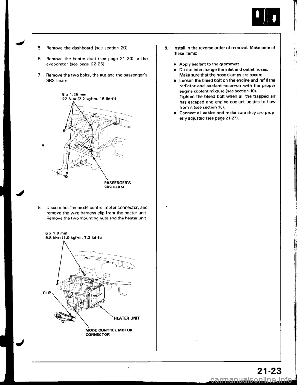
Remove the dashboard (see section 2O).
Remove the heater duct (see page 21 20) or the
evaporator lsee page 22-261.
Remove the two bolts, the nut and the passenger's
SRS beam.
PASSENGER'SSRS BEAM
Disconnect the mode control motor connector. and
remove the wire harness clip from the heater unit.
Remove the two mounting nuts and the heater unit.
6 x 1.0 mm9.8 N.m (1.0 kgf.m, 7.2 lbf.ftl
I r 1.25 mm22 N.m 12.2 kgf.m, 16 lbf'ft)
Il
I
I
lnstall in the reverse order of removal. Make note of
these items:
. Apply sealant to the grommets
. Do not interchange the inlet and outlet hoses.
Make sure that the hose clamps are secure.
. Loosen the bleed bolt on the engine and refill the
radiator and coolant reservoir with the proper
engine coolant minure (see section 10).
Tighten the bleed bolt when all the trapped air
has escaped and engine coolant begins to flow
from it (see section 10).
. Connect all cables and make sure they are prop-
erly adjusted (see page 2'l-271.
;!
i
21-23
Page 1025 of 1681
J
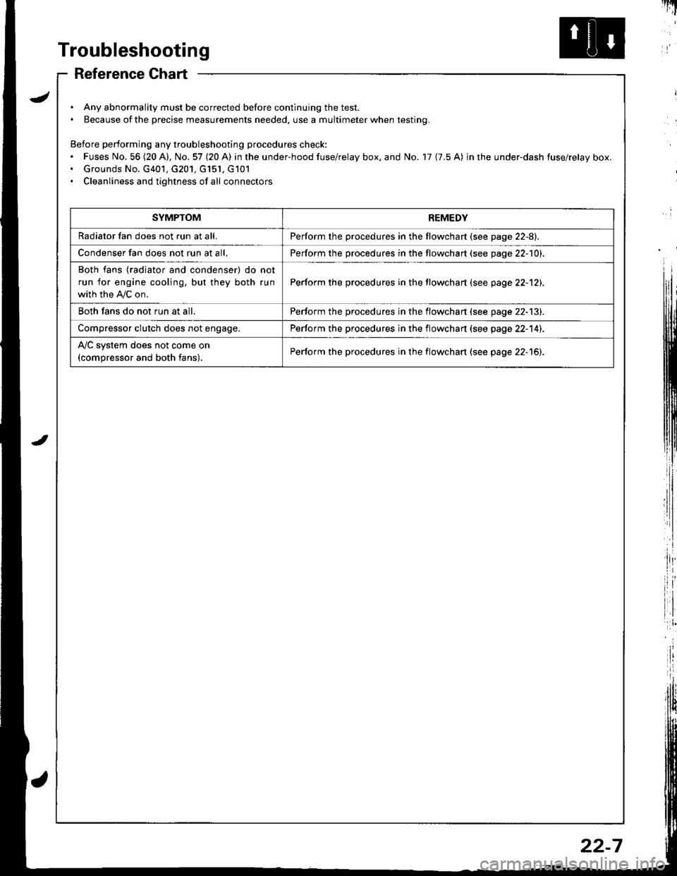
Troubleshooting
Reference Chart
. Any abnormality must be corrected before continuing the test.. Because of the precise measurements needed, use a multimeter when testing.
Before performing any troubleshooting procedures check:. Fuses No, 56 (20 A), No. 57 (20 A) in the under-hood fuse/relay box, and No. 17 {7.5 A) in rhe under-dash fuse/relay box.. Grounds No. G401, G201, G151, G101. Cleanliness and tightness of all connectors
I'IT
I
I
SYMPTOMREMEDY
Radiator fan does not run at all.Perform the procedures in the flowchart {see page 22-8).
Condenser fan does not run at all,Perform the procedures in the flowchart (see page 22-1O1.
Both fans {radiator and condenser) do not
run for engine cooling, but they both run
with the IVC on.
Perform the procedures in the tlowchart (see page 22-12).
Both fans do not run at all.Perform the procedures in the flowchart (see page 22-13).
Compressor clutch does not engage.Perform the procedures in the flowchart (see page 22-14).
l'lc system does not come on
{compressor and both fans).Perform the procedures in the flowchart (see page 22-15).
22-7
Page 1030 of 1681
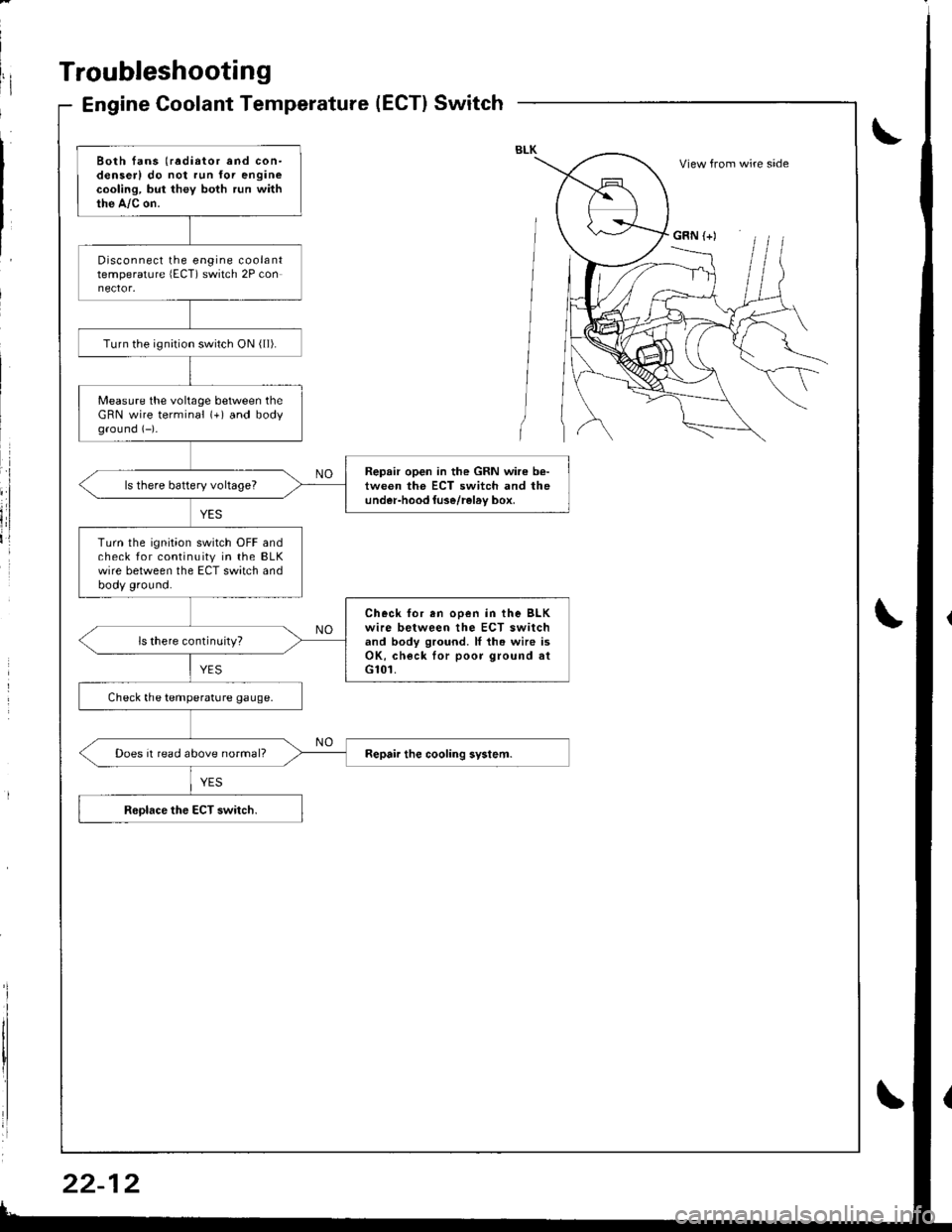
Troubleshooting
Engine Coolant Temperature(ECT}Switch
Both fans (radiator and con-denserl do not run for enginecooling, but they both run withthe A,/c on.
Disconnect the engine coolanttemperature lECT) switch 2P con
Turn the ignirion switch ON ( ll).
Measure the voltage between theGRN wire terminal (+) and bodyground (-)-
Repair open in the GRN wire b€-tween the ECT switch and theunder-hood luse/rel6v box,ls there battery voltageT
Turn the ignition switch OFF andcheck for continuity in the BLKwire between the ECT switch andbody ground.
Check for en ooen in the BLKwire between the ECT switchand body ground. ll th. wire isOK, check lor poor ground atG101.
ls there continuity?
Check the temperature gauge.
Does it read above normal?
View from wire side
GRN (+)
Page 1042 of 1681
A/C System Service
Performance Test
The performance test will help determine if the air con,
ditioner system is operating within specifications.
Use only service equipment that is U.L.-listed and is cer,
tified to meet the requirements of SAE J2210 to remove
HFC-134a (R-134a) from the air conditioner svstem.
CAUTION: Exposure to air conditioner retrigerant and
lubricant vapor or mist can irritate eyes, nose and
throat. Avoid breathing the air conditioner refrigerant
and lubricant vapor or mist.
lf accidental system discharge occurs, ventilate work
area before resuming service.
R-134a service equipment or vehicle air conditioner sys-
tems should not be pressure tested or leak tested with
compressed arr.
@ some mixtures of air and R-134a have
been shown to be combustible at elevated Dressures
and can result in fire or explosion causing iniury orproperty damage. Never use compressed air to pressure
test R-134a service equipment or vehicle air conditioner
systems.
Additional health and safety information may be
obtained from the refrigerant and lubricant manufactur-
ers.
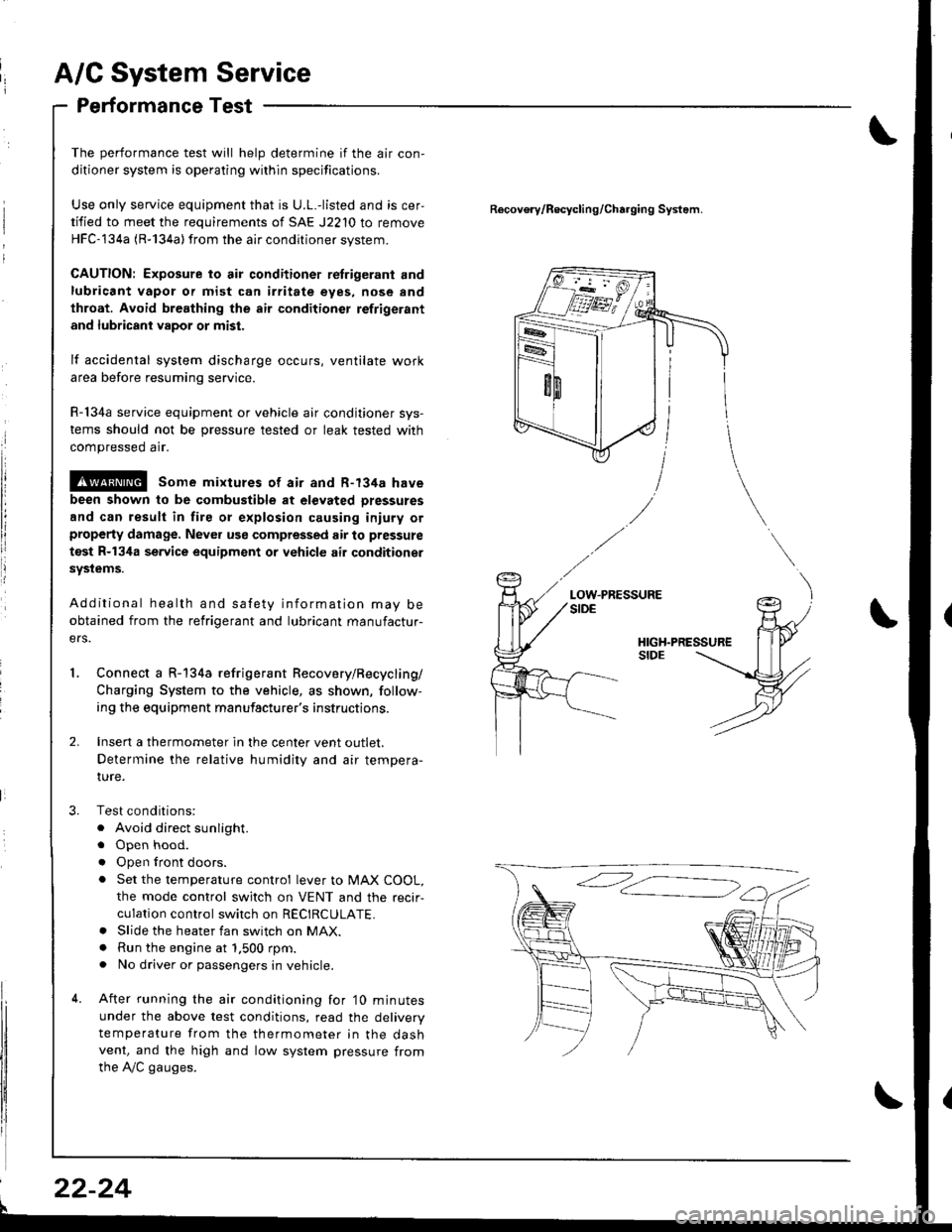
Connect a R-134a refrigerant Recovery/Recycling/
Charging System to the vehicle, as shown, follow-
ing the equipment manufacturer's instructions.
Insen a thermometer in the center vent outlet.
Determine the relative humidity and air tempera-
IUre.
Test conditions:
. Avoid direct sunlight.
. Open hood.
. Open lront doors.
. Set the temperature control lever to MAX COOL,
the mode control switch on VENT and the recir-
culation control switch on RECIRCULATE.. Slide the heater fan switch on MAX.. Run the engine at 1.500 rpm.. No driver or passengers in vehicle.
After running the air conditioning for'10 minutes
under the above test conditions, read the delivery
temperature from the thermometer in the dashvent, and the high and low system pressure from
the A,/C gauges.
Recovo.v/Recycling/Charging System.
LOW.PRESSURE
l
22-24
Page 1048 of 1681
Compressor
Replacement
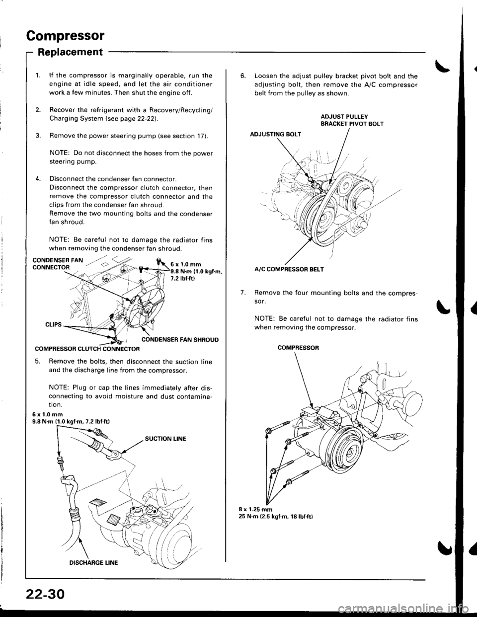
lf the compressor is marginally operable, run the
engine at idle speed, and let the air conditioner
work a few minutes. Then shut the engine off.
Recover the refrigerant with a Recovery/Recycling/
Charging System \see page 22-22).
Remove the power steering pump (see section 17).
NOTE: Do not disconnect the hoses from the power
steering pump.
Disconnect the condenser fan connector.
Disconnect the compressor clutch connector, then
remove the compressor clutch connector and the
clips from the condenser fan shroud
Remove the two mounting bolts and the condenser
fan shroud.
NOTE: Be careful not to damage the radiator fins
when removing the condenser fan shroud.
1.0 mmN.m (1.0 kgt.m,rbf.ftt
CONDENSER FAN SHROUD
COMPRESSOR CLUTCH CONNECTOR
5. Remove the bolts, then disconnect the suction line
and the discharge line from the compressor.
NOTE: Plug or cap the lines immediately aiter dis-
connecting to avoid moisture and dust contamina-
tio n.
6x1.0mm9.8 N.m (1.0 kgf.m, 7.2 lbf.ft)
22-30
6. Loosen the adjusl pulley bracket pivot bolt and the
adjusting bolt, then remove the A/C compressor
belt from the Dullev as shown.
ADJUSTING BOLT
A/C COMPRESSOR BELT
Remove the four mounting bolts and the compres-
sor.
NOTE: Be careful not to damage the radiator fins
when removing the compressor.
7.
./.,
COMPRESSOR
Page 1049 of 1681
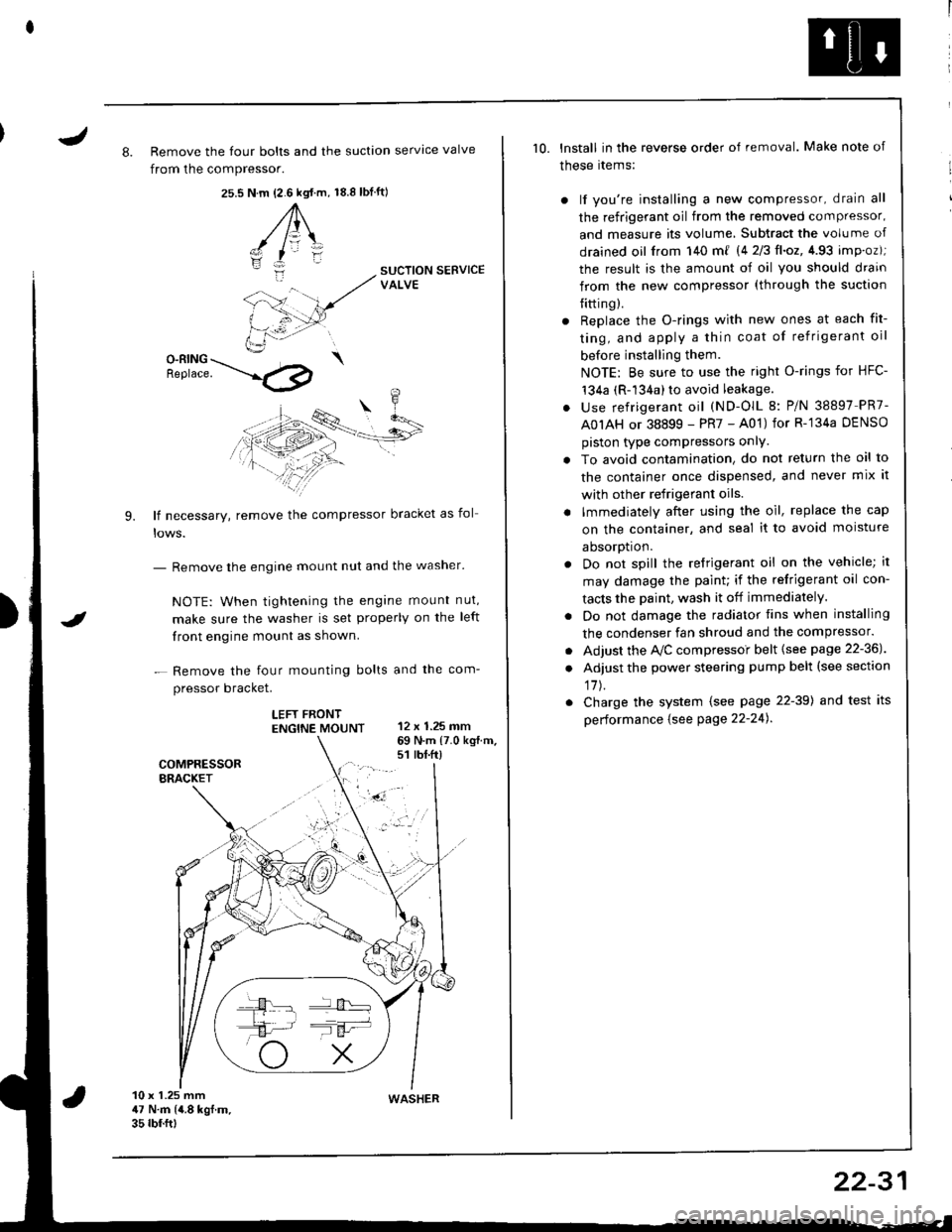
J8. Remove the four bolts and the suction servtce valve
from the compressor.
25.s18.8 tbf.ft)N.m {2.6 kgt.m,
A\
-/ l=\'zI
i:-
9.
SUCTION SERVICEVALVE
O-RING \Benrace. --'.l4p
lf necessary, remove the compressor bracket as fol
- Remove the engine mount nut and the washer'
NOTE: When tightening the engane mount nut,
make sure the washer is set properly on the left
front engine mount as shown.
- Remove the four mounting bolts and the com-
pressor bracket.
LEFT FRONTENGTNE MOUNT 12 x 1.25 mm
I
69 N.m {7.0 kg{.m.s1 rbt.ft)
10 x 1.25 mm47 N.m (4.8 kgf.m.35 rbf.ftt
10. lnstall in the reverse order of removal. Make note of
these rtems:
) lf you're installing a new compressor, drain all
the refrigerant oil from the removed compressor,
and measure its volume, Subtract the volume of
drained oil from 140 m{ 14 2/3ll.oz,4.93 imp.oz);
the result is the amount of oil you should drain
from the new compressor (through the suction
{itting).
r Replace the O-rings with new ones at each fit-
ting, and apply a thin coat of refrigerant oil
before installing them.
NOTE: Be sure to use the right O-rings for HFC-'t34a (R-134a) to avoid leakage.
. use refrigerant oil (ND-OlL 8: P/N 38897 PR7-
A0IAH or 38899 - PR7 - A01) for R-'134a DENSO
piston type compressors onlY.
. To avoid contamination, do not return the oil to
the container once dispensed, and never mix it
with other refrigerant oils.
. lmmediately after using the oil, replace the cap
on the container, and seal it to avoid moisture
aDsorDt|on.
. Do not spill the refrigerant oil on the vehicle; it
may damage the paint; if the refrigerant oil con-
tacts the Daint, wash it off immediately.
. Do not damage the radiator fins when installing
the condenser fan shroud and the compressor.
. Adjust the Ay'C compressoi belt {see page 22-36J
. Adjust the power steering pump belt (see section
17J.
. Charge the system (see page 22-39) and test its
performance {see Page 22-24).
WASHER
22-31
Page 1053 of 1681
J
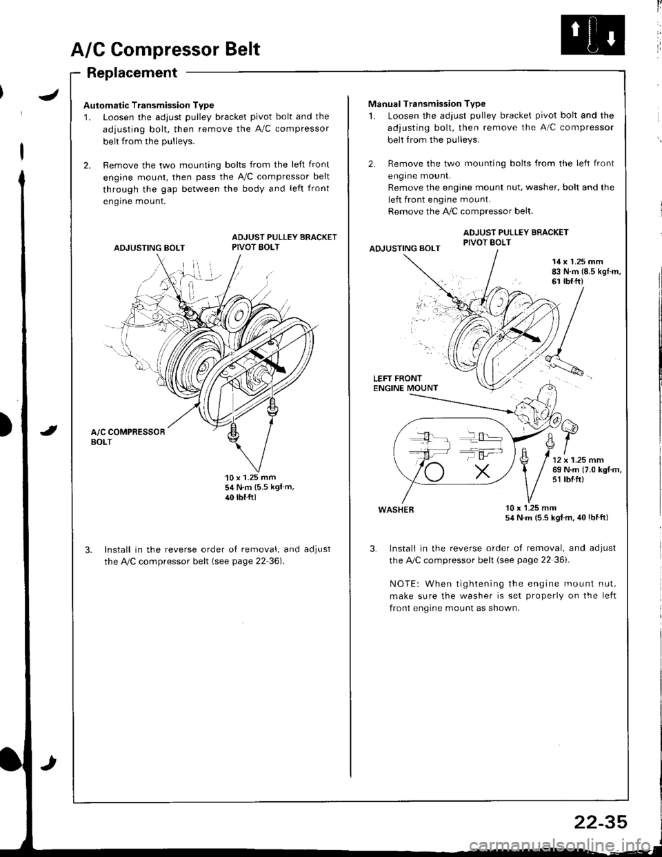
A/G Compressor Belt
Replacement
Automatic Transmission Type
1. Loosen the adjust pulley bracket pivot bolt and the
adjusting bolt. then remove the A/C compressor
belt from the Dullevs.
2. Remove the two mounting bolts from the left front
engine mount, then pass the A,/C compressor belt
through the gap between the body and left front
engrne mount.
ADJUSTING BOLT
ADJUST PULLEY BRACKETPIVOT BOLT
'10 x 1.25 mm54 N.m {5.5 kgl m,
40 rbtftl
Install in the reverse order of removal, and
the Ay'C compressor belt (see page 22 36).
aoJUsI
ll
Manual Transmission Type
1. Loosen the adjust pulley bracket pivot bolt and the
adjusting bolt, then remove the A/C compressor
belt from the pulleys.
2. Remove the two mounting bolts from the left front
engrne mount.
Remove the engine mount nut, washer, bolt and the
left front engine mount.
Remove the !i/C compressor belt.
ADJUST PULLEY BRACKETPIVOT BOLTAOJUSTING BOLT
14 x 1.25 mm83 N.m {8.5 kgl.m,61 rbf.ft)
LEFT FRONTENGINE MOUNT
wasHEB lu x l.z5 mm54 N.m (5.5 kgl m, 40lbtft)
3. Instali in the reverse order of removal, and adjust
the A,/C compressor belt (see page 22 36i.
NOTE: When tightening the engine mount nut,
make sure the washer is set properly on the left
front engine mount as shown.
T':
22-35
Page 1058 of 1681
J
Electrical
Speciaf Toofs ..........................23-2
Troubleshooting
Tips 8nd Precautions .......................,..,.,.,.,.,......,..., 23-3
Five-step Troubleshooting ............,......,.,.,...,..,....., 23-5
Schsmatic Svmbols ...............23-6
Wire Color Code3 .. ................. 23-6
Relay and Control Unit Locations
Engine Compartment ......,.,.................,.,.,.,.,.,,,, 23-7
Dashboard and Door .........,...........,.....,.,....,.,.... 23-8
Dashboard and Floor ......................................... 23-10
Ouarter Pan€f .,,.,...,.,..,...,,,23-12
Connector ldontification and WireHarness Routing ......,.,......23-'13
Index to Circuits and Systems
Airbag
* Integrated Control Unit .....,.,.,.....23-152* Interlock Sytem .,...,.,...........,. 23.146
Lights, Exterior
Eack-up LighB ..................23.187
Brake Ligh$ ......................23-190*Daytime Running Lights (Canada) ................... 23"164
Front Parking Lights .......................................... 23-173
Front Side Marker Lights .................................. 23-173
Front Turn Signal Lights ..................-.......,...,.,. 23-173* Hazard Warning Lights ....................,........,....... 23-192
Headlights.....23-169
23-253 powerDistribution..................... 23-5/r
Air Conditioning.....,....... Soction 21
Alternator ..........,................... 23.99
iCigarette Lighter .........23-212
*Cruise Control
Distributor
'.'.,.'.'.,.'...,,,,.,''.'.,.',.'''.' 23.277
.............................. 23.88
................... 23-90lgnition Timing ......
Indicator Lights
Key-in Reminder System
Maintenance Reminder System*Seat Belt R€mindor System .,...........................* Side Marker/Turn Signal/HazardFlashcr Svstem .................23-192
Spark Plugs ............................23-98
Starting System .....................23-74* Stereo Sound System ...,......,..........,...,......,.,.,.,..,., 23-196
Supplemental Restraint System (SRS) ................ 23-277
Vshicle Speed Sensor (VSS) ................................. 23.130r Wiper/Washer System .........................................., 23-265
*Read SRS precautions on Psge 23-283 before working
in those areas,
23-154
23.136
23"133