Mount HONDA INTEGRA 1998 4.G Owner's Manual
[x] Cancel search | Manufacturer: HONDA, Model Year: 1998, Model line: INTEGRA, Model: HONDA INTEGRA 1998 4.GPages: 1681, PDF Size: 54.22 MB
Page 332 of 1681
1r
;
J
I
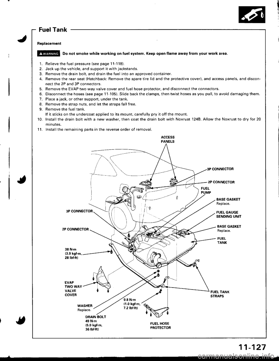
Fuel Tank
Reolacement
!!@ Do not smoke while working on fuel system. Keep open flame away from your work a.ea.
1. Relieve the fuel pressure(seepagell-118).
2. Jack up the vehicle, and support it with jackstands.
3. Remove the drain bolt, and drain the fuel into an approved container.
4. Remove the rear seat (Hatchbackt Remove the spare tire lid and the protective cover), and access panels, and discon-
nect the 2P and 3P connectors.
5. Remove the EVAP two way valve cover and fuel hose protector, and disconnect the connectors.
6. Disconnect the hoses (see page 11-105). Slide back the clamps, then twist hoses as you pull, to avoid damaging them.
7. Place a tack, or other support, under the tank.
8. Remove the strap nuts, and let the straps fall free.
9. Remove the fuel tank.
lf it sticks on the undercoat applied to its mount, carefully pry it offthe mount.
10. lnstallthe drain bolt with a new washer, then coat the drain bolt with Noxrust 1248. Allow the Noxrust to dry tor 20
minutes.
11. Installthe remaining parts in the reverse order of removal.
ACCESSPANELS
CONNECTOR
2P CONNECTOR
3P CONNECTOR
2P CONNECTOR
EASE GASKETReplace.
FUEL GAUGESENDING UNIT
BASE GASKETReplace.
FUELTANK
38 N.m13.9 kgtm,28 tbf.ftl
EVAPTWO WAYVALVECOVERFUEL TANKSTNAPS
WAS}IERReplace.
9.8 N.m{1.0 kgf.m,7.2 tbt.tll
ORAIN BOLTilg N.m(5.0 k9f.m.36 rbf.ftl
FUEL HOSEPROTECTOR{
11-127
Page 346 of 1681
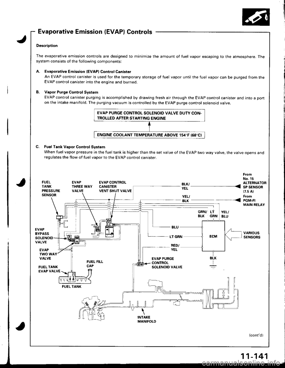
Evaporative Emission (EVAP) Controls
,J
a
DescriDtion
The evaporative emission controls are designed to minimize the amount of luel vapor escaping to the atmosphere. Thesystem consists of the following components:
A. EvaporativeEmission lEVAPlControlCanister
An EVAP control canister is used for the temporary storage of fuel vapor until the fuel vapor can be purged from theEVAP control canister into the engine and burned.
B. Vapol Purge Control System
EVAP control canister purging is accomplished by drawing fresh air through the EVAP control canister and into a pon
on the intake manifold. The purging vacuum is controlled by the EVAP purge control solenoid valve.
C. Fuel Tank Vapor Control System
When fuel vapor pressure in the fuel tank is higher than the set value of the EVAP two way valve, the varve opens anoregulates the flow of fuel vapor to the EVAP control canister.
FrcmNo. 15FUELTANKPRESSURESENSOR
EVAPTHREE WAYVALVE
EVAP CONTROLCANISTENVENT SHUT VALVE
YEL/- BLK
EVAPBYPASSSOLENOIDVALVE
LT GRN
RED/EVAPTWO WAYVALVE
FUEL TANKEVAP VALVE
FUEL TANK
EVAP PURGE CONTROL SOLENOID VALVE DUTY CON-
TROLLED AFTER STARTING ENGINE
?!l ---- 311'AiS-*(7.s Al
FromPGM.FIMAIN RELAY
VARIOUSSENSORS
----<
YEL
EVAP PURGECONTROLSOLENOID VALVE
(cont'd)
-141
Page 366 of 1681
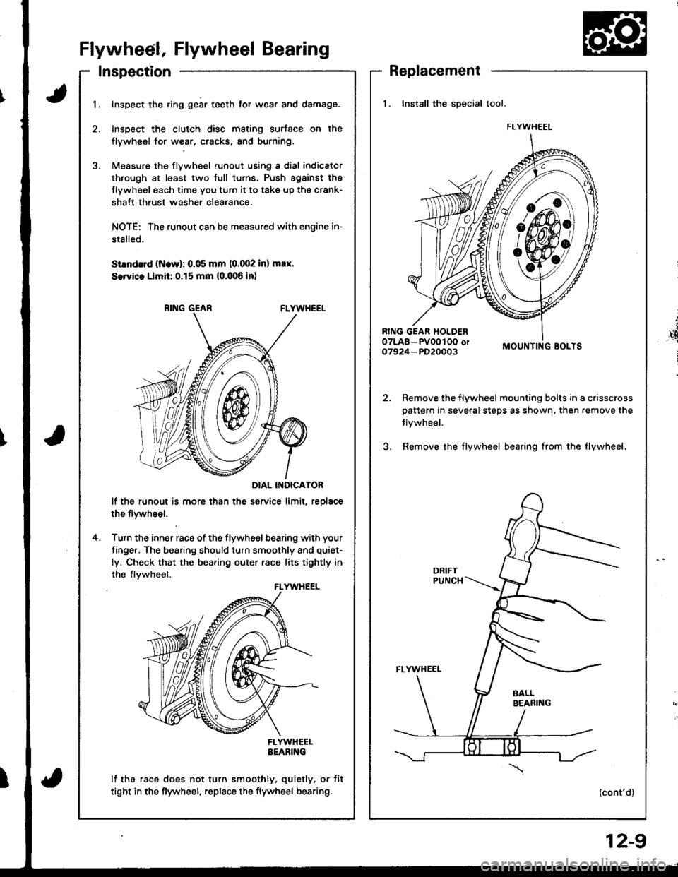
Flywheel, Flywheel Bearing
Inspection
t
',4
i
Replacement
1. Install the special tool.
MOUNTING BOLTS
Remove the flywheel mounting bolts in a crisscrosspattern in several steps as shown, then.emove the
Jlvwheel.
Bemove the flywheel bearing from the flywheel.
(cont'd)
FLYWHEEL
I
1.Inspect the ring gear teeth tor wear and damage.
Inspect the clutch disc mating surtace on the
flywheel for wear, cracks, and burning.
l\,reasure the flywheel runout using a dial indicator
through at least two full turns. Push agsinst the
Jlywheel each time you turn it to take up the crank-
shatt thrust washer clearance.
NOTE: The runout can ba measured with engine in-
stalled.
SiEndrrd (Ncw): 0.05 mm (0.002 inl max.
SerYicc Llmh: 0.15 mm (0.006 inl
DIAL INOICATOR
lf the runout is more than the service limit, reolace
the flywheel.
Turn the inner race of the flywheel bearing with your
tinger. The bearing should turn smoothly and quiet-
ly. Check that the bearing outer race tits tightly in
the flvwheel.
FLYWHEELBEARING
lf the race does not turn smoothly, quietly, or tit
tight in the flywheel, replace the flywheel bearing.
4.
FLYWHEEL
12-9
Page 367 of 1681
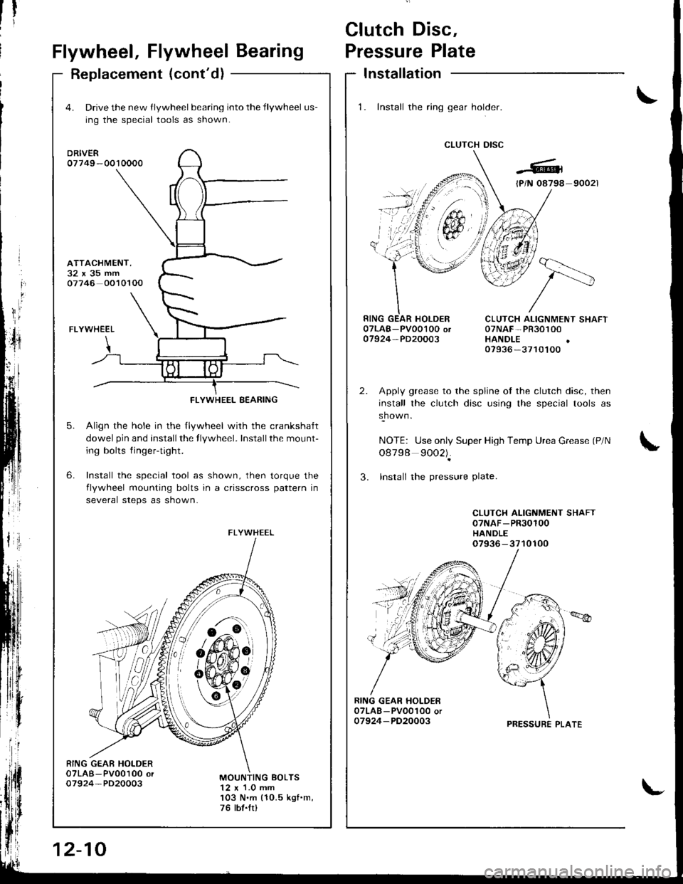
Clutch Disc,
Flywheel, Flywheel BearingPressure Plate
Replacement (cont'd)Installation
1. Install the ring gear holder.
CLUTCH DISC
1tti
CLUTCH ALIGNMENT SHAFT07NAF-PR30100HANDLE07936 -3710100
Apply grease to the spline ot the clutch disc, then
install the clutch disc using the special tools as
shown.
NOTE: Use only Super High Temp Urea Grease (P/N
o8798 9002).
3. Insrall the pressure Plate.
CLUTCH ALIGNMENT SHAFT07NAF-PR30100HANDLE07936-3710100
RING GEAR HOI-DER07LAB - PV001O0 or07924-PD20003
4. Drive the new flywheel bearing into the flywheel us-
ing the special tools as shown.
DRIVER07749 -0010000
FLYWHEEL
Align the hole in the llywheel with the crankshalt
dowel pin and installthe flywheel. Installthe mount-
ing bolts fingertight.
Install the special tool as shown, then torque the
flvwheel mounting bolts in a crisscross pattern in
several steps as shown-
6.
ATTACHMENT,32x35mm07746 0010100
5.
RING GEAE HOLDER07LAB-Pv00100 or07924-PD20003MOUNTING BOLTS12 x 1.0 mm103 N.m (10.5 kgf .m,
76 tbt.frl
FLYWHEEL BEARING
FLYWHEEL
6!-o
&#,oit
12-10
PRESSURE PLATE
Page 368 of 1681
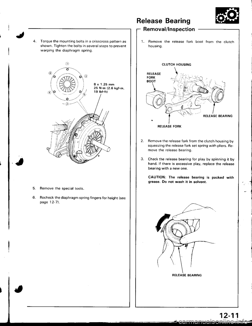
Release Bearing
Removal/lnspection
1. Remove the release fork
housrng.
boot from the clutch
5.
6.
Torque the mounting bolts in a crisscross pattern as
shown. Tighten the bolts in several steps to prevent
warping the diaphragm spring.
8 x 1.25 mm25 N.m {2.6 kgf.m,19 tb{.fr}
Remove the special tools.
Recheck the diaphragm spring fingers for height {seepage 12-7).
CLUTCH HOUSING
BELEASE AEAFING
RELEASE FORK
Remove the release fork from the clutch housing by
squeezing the release fork set spring with pliers. Re
move the release bearing.
Check the release bearing for play by spinning it by
hand. lf there is excessive play, replace the release
bearing with a new one.
CAUTION: The release bearing is packed wirhgrease. Do not wash it in solvent.
a;;;:
S",€ r
K4IN/
RELEASE BEARING
Page 374 of 1681
I
T
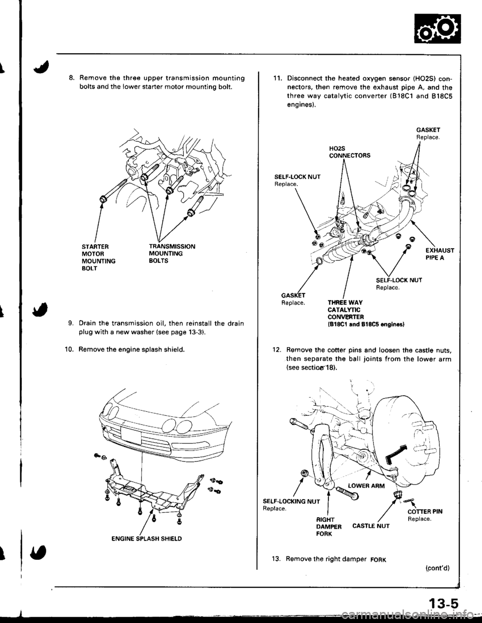
Remove the three upper transmission mounting
bolts and the lower starter motor mountino bolt.
STARTERMOTOEMOUNTINGBOLT
Drain the transmission oil, then reinstall the drainplug with a new washer (see page 13-3).
Remove the engine splash shield.10.
11.
6tr!
/
SELF.LOC1(ING NUTReplace.
Disconnect the heated oxygen sensor (HO2S) con-
nectors, then remove the exhaust pipe A. and the
three way catalytic converter (B'18C1 and B18C5
engines).
Feplace. THREE WAYCATALYNCCONVERTENlg18C1 lnd 818C5 onginrsl
Remove the cotter pins and loosen the castle nuts,
then separate the ball joints from the lower arm(see sectiotr'l8).
LOWER ARM
DAMPER CASTLE NUTFORK
13. Remove the right damper FORK
(cont'd)
13-5
Page 406 of 1681
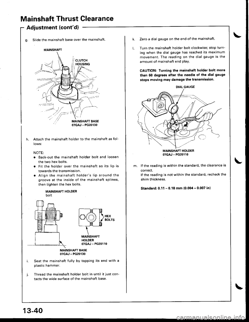
Mainshaft Thrust Clearance
g. Slide the mainshaft base over the mainshaft.
Adjustment (cont'dl
/\
/-
MAINSHAFT BASE07GAJ - PG20130
Aftach the mainshaft holder to the mainshaft as fol-
lows:
NOTE:
o Eack-out the mainshaft holder bolt and loosen
the two hex bolts.
. Fit the holder over the mainshaft so its lip is
towards the transmission.
. Align the mainshaft holder's lip around the
groove at the inside of the mainshaft splines,
then tighten the hex bolts.
MAINSHAFT HOLDERbolt
MAINSHAFT BASE07GAJ - PG20130
Seat the mainshaft fully by tapping its end with a
plastic hammer.
Thread the mainshaft holder bolt in until it just con-
tacts the wide surface of the mainshaft base.
MAINSHAFT
f----M---E
|".ffi f\.xex
I \J \--l./ l/ Borrs
L- LE
\
MAINSHAfiHOLDER07GAJ - PG20110
13-40
Zerc a dial gauge on the end of the mainshaft.
Turn the mainshaft holder bolt clockwise; stop turn-
ing when the dial gauge has reached its maximum
movement. The reading on the dial gauge is the
amount of mainshaft end plav.
CAUTION: Turning the mainshaft holder bolt more
than 60 degrees after the needle of the dial gauge
stops moving may damage the transmission.
MAINSHAFT HOLDER07GAJ - PG20110
lf the reading is within the standard, the clearance is
correct.
It the reading is not within the standard, recheck the
shim thickness.
Standard: 0.11 - 0.18 mm (0.004 - 0.007 in)
DIAL GAUGE
Page 408 of 1681
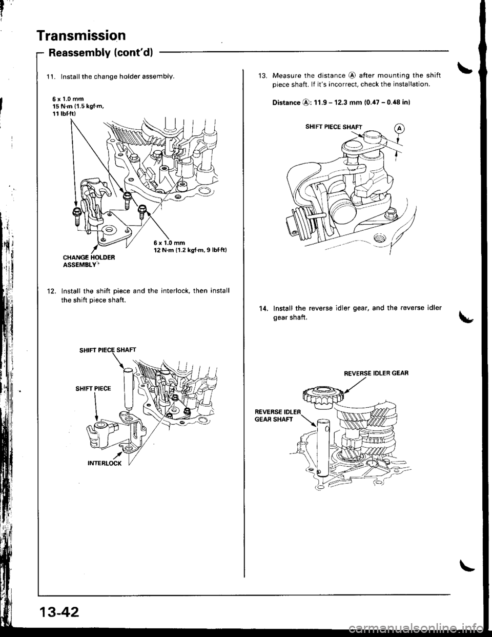
Transmission
Reassembly (cont'dl
1't. lnstallthe change holder assembly.
6x1.0mm15 N.m ('1.5 kgf.m,11 rbf.ft)
lnstall the shift piece and the
the shift piece shaft.
interlock, then install't2.
6x1.0mm12 N.m 11.2 kg{.m,I lbf.ftl
13-42
13. Measure the distance @ after mounting the shift
piece shaft. lf it's incorrect, check the installation.
Distance @: 11.9 - 12.3 mm (0.47 - 0.48 inl
Install the reverse idler gear, and the reverse
gear shaft,
idler14.
REVERSE IDLER GEAR
Page 412 of 1681
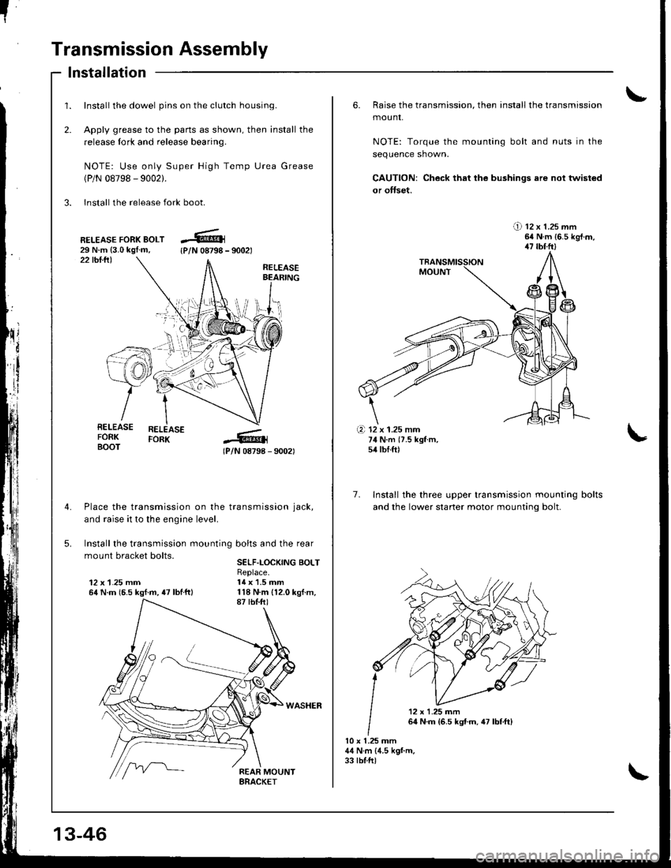
I
Transmission Assembly
1.
2.
Install the dowel pins on the clutch housing.
Apply grease to the parts as shown, then install the
release fork and release bearing.
NOTE: Use only Super High Temp Urea Grease
(P/N 08798 - 9002).
3. Install the release fork boot.
lnstallation
22 tbl.lll
RELEASE FORK BOLT29 N.m {3.0 kgl.m,{P/N 08798 - 9002t
RELEASEBEAFING
RELEASEFORK
lPlN 08798 - 90021
Place the transmission on the transmission jack,
and raise it to the engine level.
Install the transmission mounting bolts and the rear
mount bracket bolts.SELF.LOCKING BOLT
12 x 1.25 mm64 N.m {6.5 kgf.m, {7 lbtftl
Replace.14 x 1.5 mm
RELEASEFORKBOOT
\i'l-r )i-
.+.i
13-46
6. Raise the transmission, then install the transmission
mounr,
NOTE: Torque the mounting bolt and nuts in the
sequence shown.
CAUTION: Check that the bushings are not twisted
or offset.
!) tz x t.zs mm64 N.m {6.5 kgt.m,47 tbl.ftl
7. Install the three upper transmission mounting
and the lower staner motor mountinq bolt.
bolts
10 x 1.25 mm44 N.m (4.5 kgt m.33 tblftl
(a 12 x 1.25 mm74 N.m {7.5 kgf m,54 tbf.ft)
'12x1.25m�n
64 N.m {6.5 kst.m,47 lbf,ft)
Page 413 of 1681
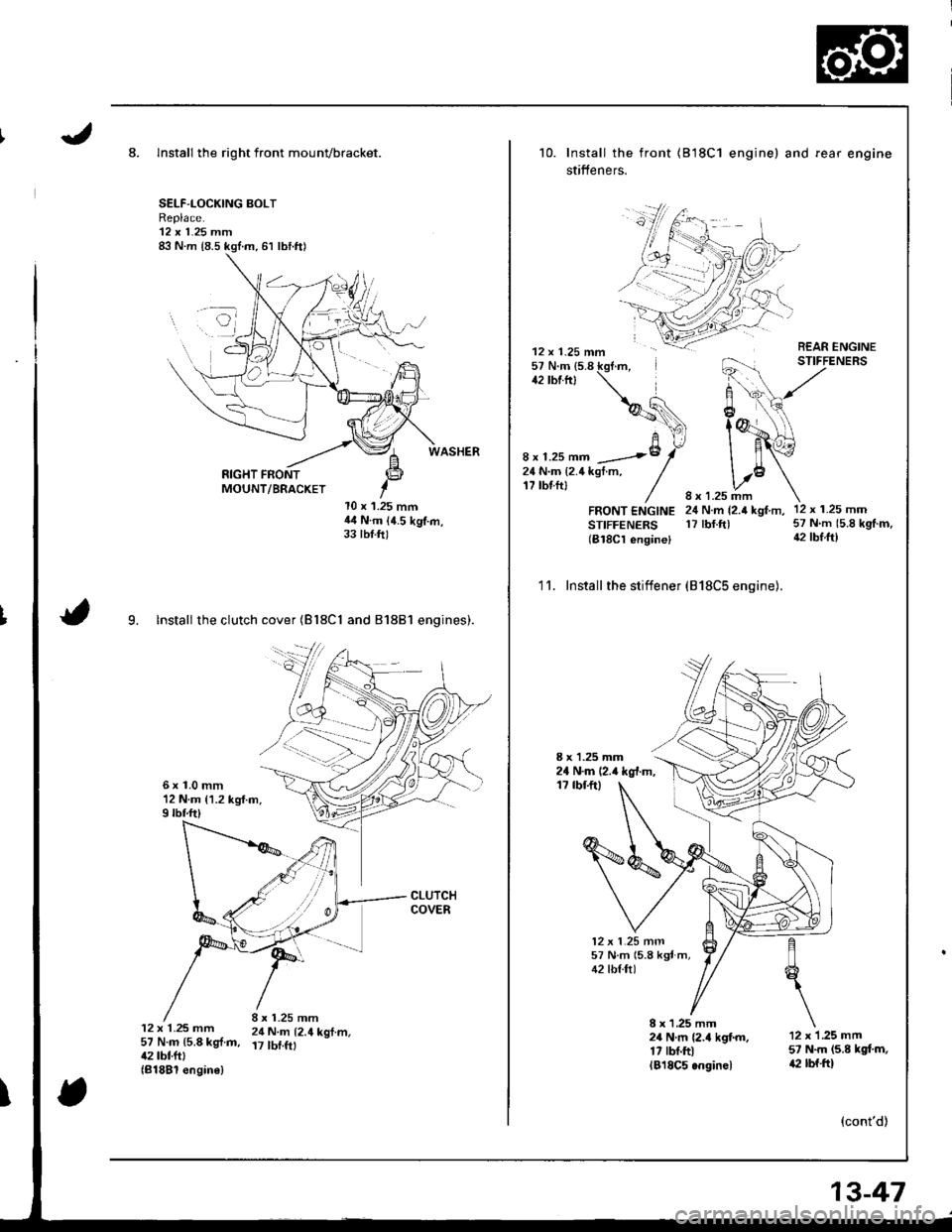
8. Install the right front mounvbracket.
SELF-LOCKING BOLTReplace.'12 x 1.25 mm
RIGHT FRONTMOUNT/BRACKET
l0 x 1.25 mmil4 N.m (4.5 kg'f.m,33 tbt.ft)
9. lnstall the clutch cover (Bl8Cl and 81881 engines).
6x1.0mm12 N.m {1.2 kg{.m,9 rbf.ft)
12 x 1.25 mm 24 N.m t2.4 kof.m.57 N.m {5.8 kg{.m, 17 tbf.ftt42 tbt.ftl(81881 engin€)
10. Install the front
stifteners.
(818C1 engine) and fear engine
REAR ENGINESTIFFENERS
12 x 1.25 mm57 N'm 15.8 kg{.m.42 tbr.ltl
H!\,
f @^\
I B'�{o| \-
1.25 mmN.m {2.4 kgf m,rbf.ftl
12 x 1.25 mm57 N.m (5.8
{2 tbtft}
8 x 1.25 mm -8
24 N.m {2.4 kgt m,17 tbtftl
FRONT ENGINESTIFFENERS(B18Cl engine)
12 x 1.25 mn157 N m (5.8 kgt m,42 tbl.ftl
2111
'11. Install the stiffener (818C5 engine).
8 x 1.25 mm24 N.m (2.4 kg{.m,1? tbf.ftl
8 x 1 ,25 mm24Nm{2.4kgtm.17 rbr.ftllBl8C5.nginel
12 x 1 .25 mm57 N.m (5.8 kgl.m,a2 rbf.ftl
(cont'd)
13-47