Mount HONDA INTEGRA 1998 4.G Repair Manual
[x] Cancel search | Manufacturer: HONDA, Model Year: 1998, Model line: INTEGRA, Model: HONDA INTEGRA 1998 4.GPages: 1681, PDF Size: 54.22 MB
Page 653 of 1681
System Description
Fluid Flow Diagram
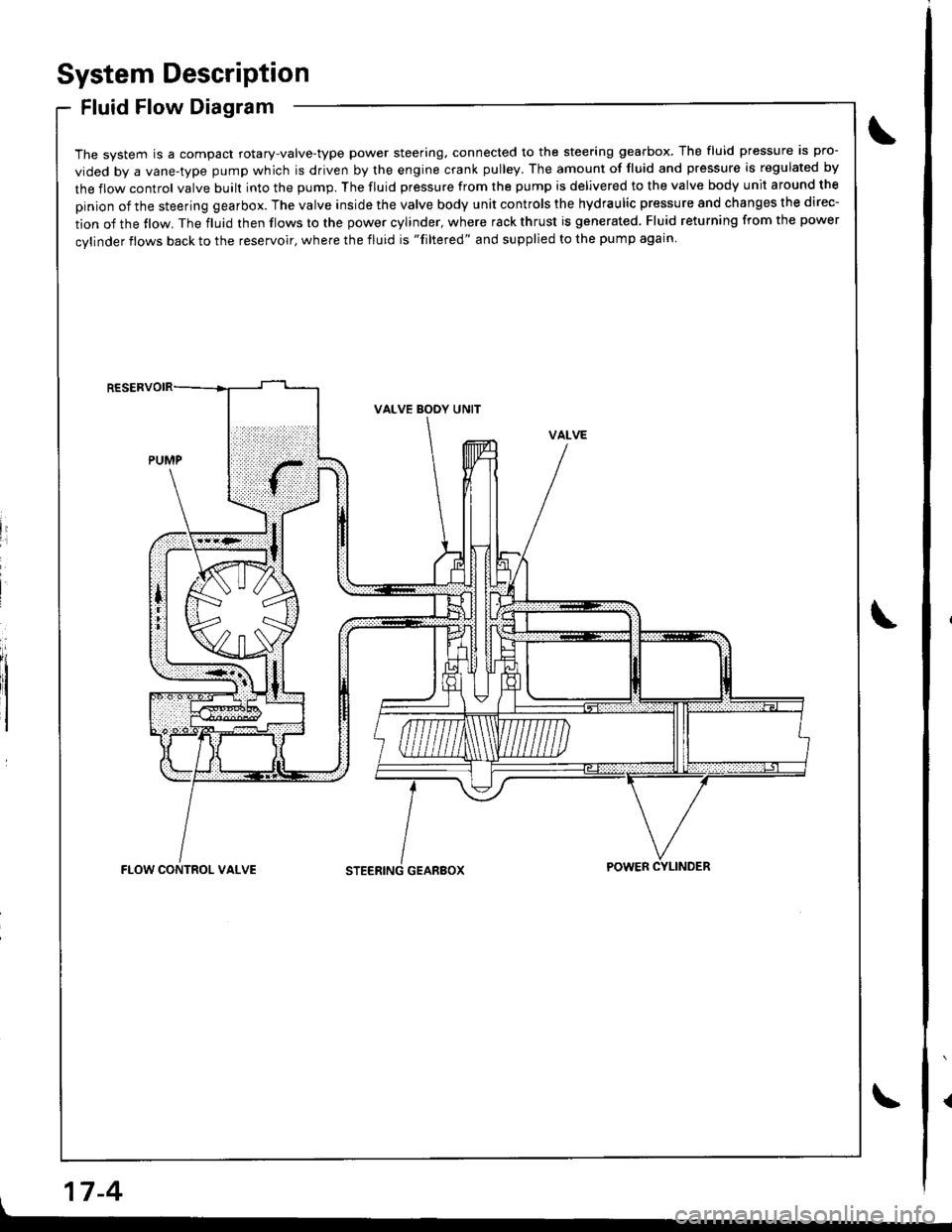
The system is a compact rotary-valve-type power steering, connected to the steering gearbox. The fluid pressure is pro-
vided by a vane-type pump which is driven by the engine crank pulley. The amount of fluid and pressure is regulated by
the flow control valve built into the pump. The fluid pressure from the pump is delivered to the valve body unit around the
pinion of the steering gearbox. The valve inside the valve body unit controls the hydraulic pressure and changes the direc-
tion of the tlow. The fluid then flows to the power cylinder, where rack thrust is generated. Fluid returning from the power
cylinder flows back to the reservoir, where the fluid is "filtered" and supplied to the pump again
li
I
VALVE BODY UNIT
GEARBOXFLOW CONTROL VALVEPOWER CYLINDER
17-4
Page 655 of 1681
System Description
Steering Pump (cont'd) .
17-6
Flow Control
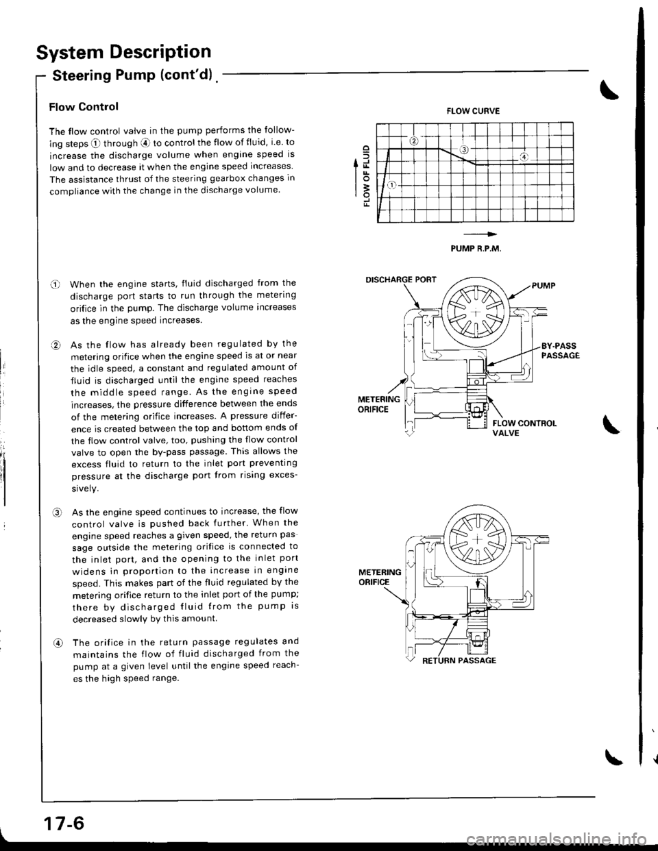
The flow control valve in the pump performs the follow-
ing steps O through aE ro control the flow of fluid, i.e. to
increase the discharge volume when engine speed is
low and to decrease it when the engine speed increases
The assistance thrust of the steering gearbox changes in
compliance with the change in the discharge volume.
When the engine starts, fluid discharged from the
discharge port starts to run through the metering
ori{ice in the pump. The discharge volume increases
as the engine speed increases.
As the flow has already been regulated by the
metering orifice when the engine speed ls at or near
the idle speed, a constant and regulated amount of
fluid is discharged until the engine speed reaches
the middle speed range. As the engrne speed
increases, the pressure difference between the ends
of the metering orifice increases. A pressure differ-
ence is created between the top and bottom ends of
the flow control valve, too, pushing the flow control
valve to open the by-pass passage. This allows the
excess fluid to return to the inlet port preventing
pressure at the discharge port trom rising exces-
As the engine speed continues to increase, the flow
control valve is pushed back further' When the
engine speed reaches a given speed, the return pas
sage outside the melering orifice is connected to
the inlet port, and the opening to the inlet port
widens in prooortion to the increase in engine
speed. This makes part of the fluid regulated by the
metering orifice return to the inlet port of the pump;
there by discharged Iluid lrom the pump rs
decreased slowlv by this amount
The orifice in the return passage regulates and
maintains the flow of fluid discharged from the
pump at a given level untilthe engine speed reach-
es the high speed range.
o
fd
lot3rotr
FLOW CURVE
PUMP R,P.M,
o-l
a,
II
,a\
METERINGORIFICE
an
Page 668 of 1681
I
Steering Linkage and Gearbox
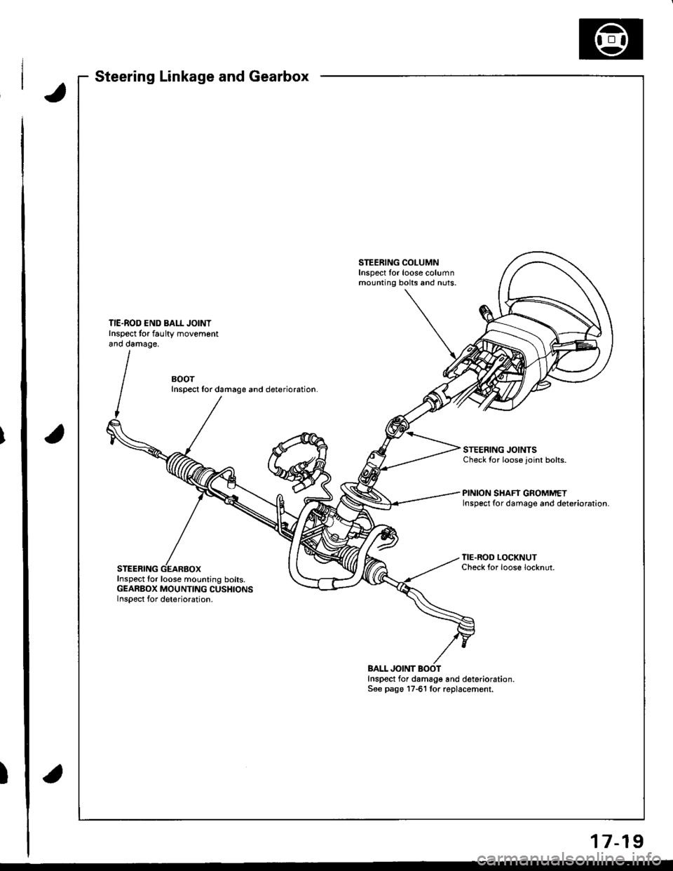
STEERING COLUMNInspect tor loose columnmounting bolts and nuts.
TIE.ROD END BALL JOINTInspect tor faultv movementano oamage,
BOOTInspect lor damage and deterioration.
STEERING JOINTSCheck {or loose joint bolts.
PINION SHAFT GROMMETInsp6ct for damage and deterioration.
STEERING
TIE.ROD LOCKNUTCheck {or loose locknut.
Inspect for loose mounting bolts.GEARBOX MOUNTING CUSHIONSInspect for deterioration.
BALL JOINTInspect for damage and deterioration.See pago 17-61 lor replacement.
17-19
Page 669 of 1681
Inspection and Adjustment
Pump Belt
NOTE: When using a new belt, first adjust the deflection
or tension to the values for the new belt, then readjust
the deflection or tension to the values for the used belt
after running engine for five minutes,
Inspection
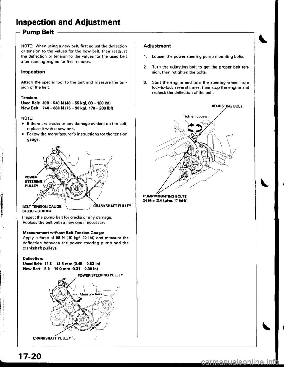
Attach the soecial tool to the belt and measure the ten-
sion of the belt.
Tension:
Usad Belt: 390 - 54O N {/10 - 55 kgf. 88 - 120 lbf}
Nsw Belt: 740 - 880 N {75 - 90 kgf. 170-2(X)lbf)
NOTE:
. lf there are cracks or any damage evident on the belt,
replace it with a new one.
. Follow the manufacturer's instructions for the tension
gauge.
ii
:i
i
I
,;h
,lt l
I
i
CRANKSHAFT PULEYBELT TENSION GAUGE07JGG - 001010A
Inspect the pump belt for cracks or any damage.
Replace the belt with a new one if necessary.
Mea3urement without Bah Tonsion Gaugo:
Apply a force of 98 N {10 kgt,22 lbll and measure the
deflection between the power steering pump and the
crankshaft pulleys,
Drllection:
Us.d B6h: 11.5 - 13.5 mm (0.45 - 0.53 in)
New Bsh: 8.0 - 10.0 mm 10.31 - 0.39 inl
POWER STEERING PULLEY
17-20
Adiustment
1. Loosen the power steering pump mounting bolts.
2. Turn the adjusting bolt to get the proper belt ten-
sion, then retighten the bolts.
3. Stan the engine and turn the steering wheel from
lock-to-lock several times. then stop the engine and
recheck the deflection of the belt.
24 N.m l2.a kgf.m, 17 lbf.ftl
Page 684 of 1681
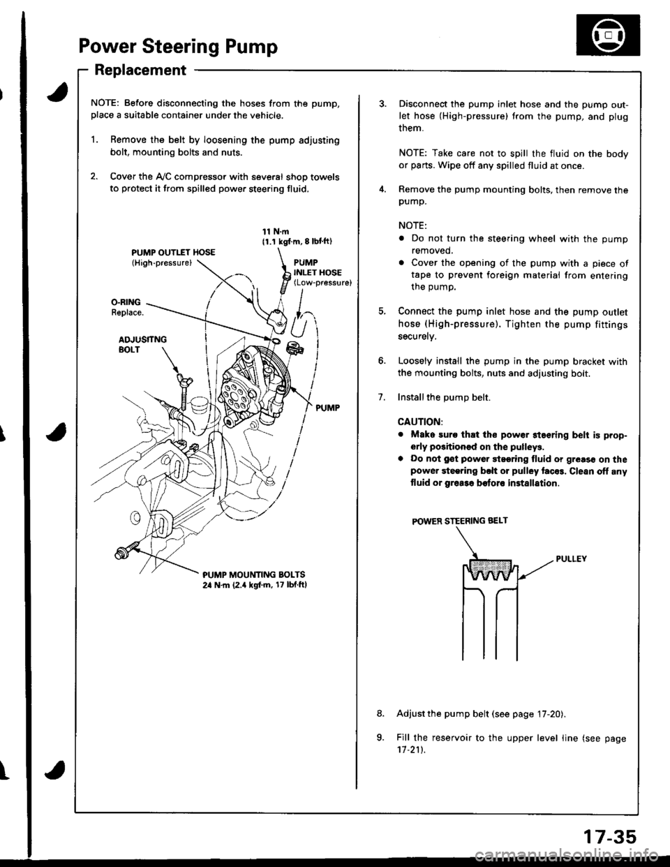
Power Steering Pump
Replacement
NOTE: Before disconnecting the hoses from the pump,
place a suitable container under the vehicle.
1. Remove the belt by loosening the pump adjusting
bolt, mounting bolts and nuts.
2. Cover the Ay'C compressor with several shop towels
to protect it from spilled power steering fluid,
11 N.m11.1 kgf.m, 8 lbl ft)
PUMPINLET HOSE(Low-pressure)
O.RINGReplace.
ADJUSTTNGBOLT
?UMP MOUt'lTlNG BOLTS2a N.m (2.a kgf.m, 17 lbf.ftl
t
7.
Disconnect the pump inlet hose and the pump out-
let hose (High-pressure) trom the pump, and plug
them.
NOTE: Take care not to spill the fluid on the body
or parts. Wipe off any spilled fluid at once.
Remove the pump mounting bolts, then remove thepump.
NOTE:
. Do not turn the steering wheel with the pump
removed,
. Cover the opening of the pump with a piece oftape to prevent foreign materiai from entering
the oumo.
Connect the pump inlet hose and the pump outlet
hose (High-pressure). Tighten the pump fittings
securelv,
Loosely install the pump in the pump bracket with
the mounting bolts, nuts and adjusting bolt.
Installthe DumD belt.
CAUTION:
. Mako suro that the power staering belt is prop-
erly positioned on the pulleys.
a Do not gst powor 9t99ring fluid or greas€ on thepower steering bclt or pulley facos. Clesn off any
tluid or grea3a botoro installation
POWER STEERING BEI-T
Adjust the pump belt (see page 17-20).
Fill the reservoir to the upper level line (see page'11.211.
8.
a
17-35
Page 692 of 1681
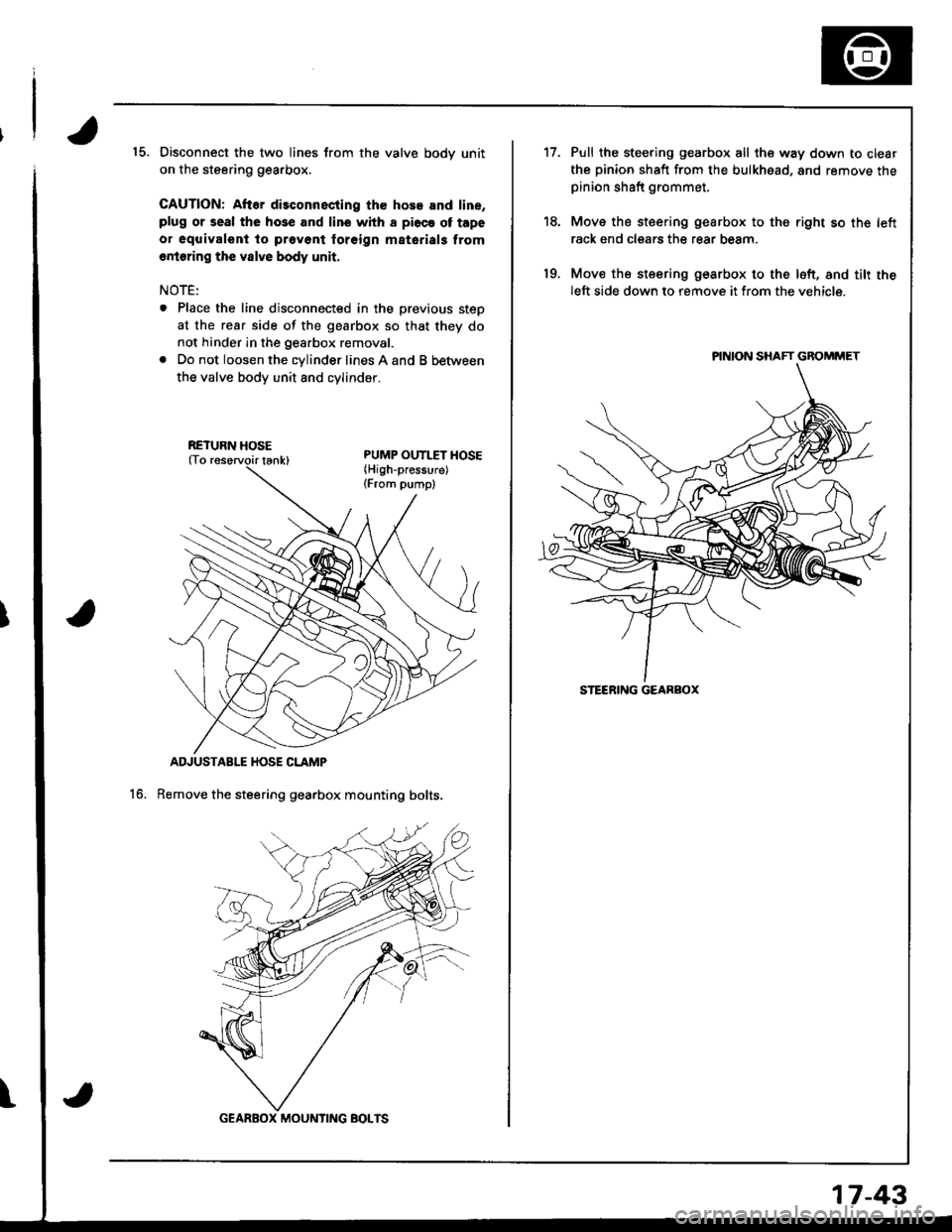
15. Disconnect the two lines from the valve bodv unit
on the steering gearbox.
CAUTION: After disconnscting the hose and line,plug or seal the hose and lino whh I pi6ce ot tape
o. oquivalent to prevont foreign matarials from
6rioring the vslve body unit,
NOTE:
. Place the line disconnected in the previous steD
at the rear side of the gearbox so that they do
not hinder in the gearbox removal.
. Do not loosen the cylinder lines A and B between
the valve body unit 8nd cvlinoer.
ADJUSTABLE HOSE CLAMP
Remove the steering gearbox mounting bolts.16.
\
RETURN HOSE
GEARBOX MOUNTING BOTTS
17-43
't7.
19.
Pull the steering gearbox all the way down to clear
the pinion shaft from the bulkhead, and remove thepinion shaft grommet.
Move the steering gearbox to the right so th€ left
rack end clears the rear beam.
Mov€ the steering gearbox to the loft, and tilt theleft side down to remove it from the vehicle.
PINION SHAFT GBOMMET
STEERING GEARBOX
Page 708 of 1681
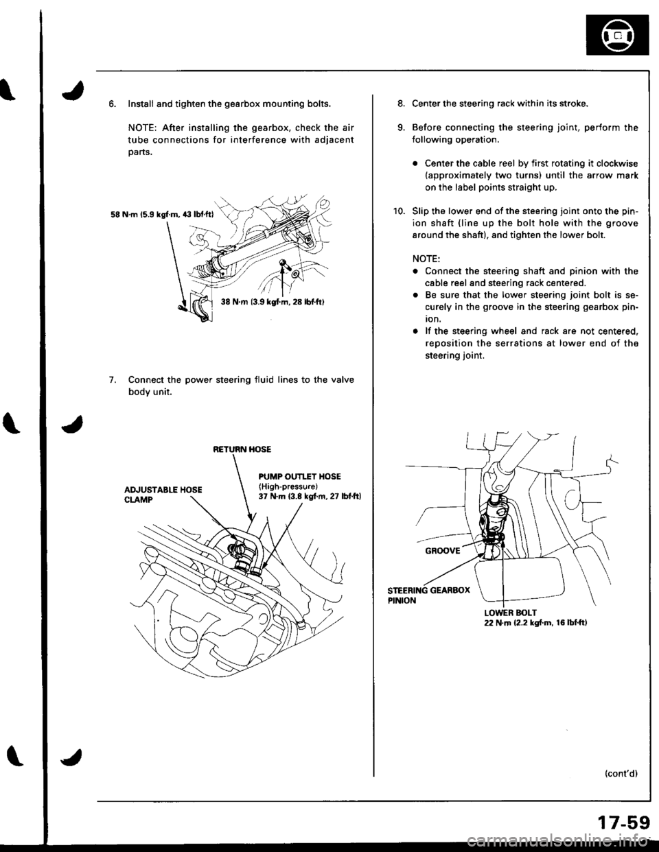
Install and tighten the gearbox mounting bolts.
NOTE: After installing the gearbox, check the air
tube connections for interference with adjacent
parts.
58 N.m 15.9 kgl.m, 43 lbf.ftl
Connect the power steering fluid lines to the valve
body unit.
7.
38 N.m {3.9 kgt m, 28 lbf.ftl
RETURN HOSE
PUMP OUTI.TY HOSE(High-pressure)
37 N.m (3.8 kgf.m, 27 lbt.ftl
Center the steering rack within its stroke.
Before connecting the steering joint, perform the
lollowing operation.
. Center the cable reel by first rotating it clockwise(approximately two turns) until the arrow mark
on the label points straight up,
Slip the lower end of the steering ioint onto the pin-
ion shaft {line up the bolt hole with the groove
around the shaft), and tighten the lower bolt.
NOTE:
. Connect the steering shaft and pinion with the
cable reel and steering rack centered.
. Be sure that the lower steering joint bolt is se-
curely in the groove in the steering gearbox pin-
ion.
o lf the steering wheel and rack are not centered,
reoosition the serrations at lower end of the
steering joint.
(cont'd)
LOWER BOLT22 N.m {2.2 kgf.m, 16 lbf.ft,
17-59
Page 715 of 1681
\
Front Toe Inspection/AdjustmentRear Toe Inspection/Adjustment
NOTE: Use commercially-available computerized four
whesl alignment equipment to measure wheel align-
ment (caster, camber, toe. and turning angle). Follow
the equipment manufacturer's instructions.
1.
2.
Check the tire pressure.
C€nter steering wheel spokes.
Check the toe with the wh€els pointed straight
ahead.
Front to6: 0 i 2 mm (0 t 1/16 in)
- lf adjustment is required. go on to step 4.
- lf no adjustment is required, remove alignment
equrpm€nr,
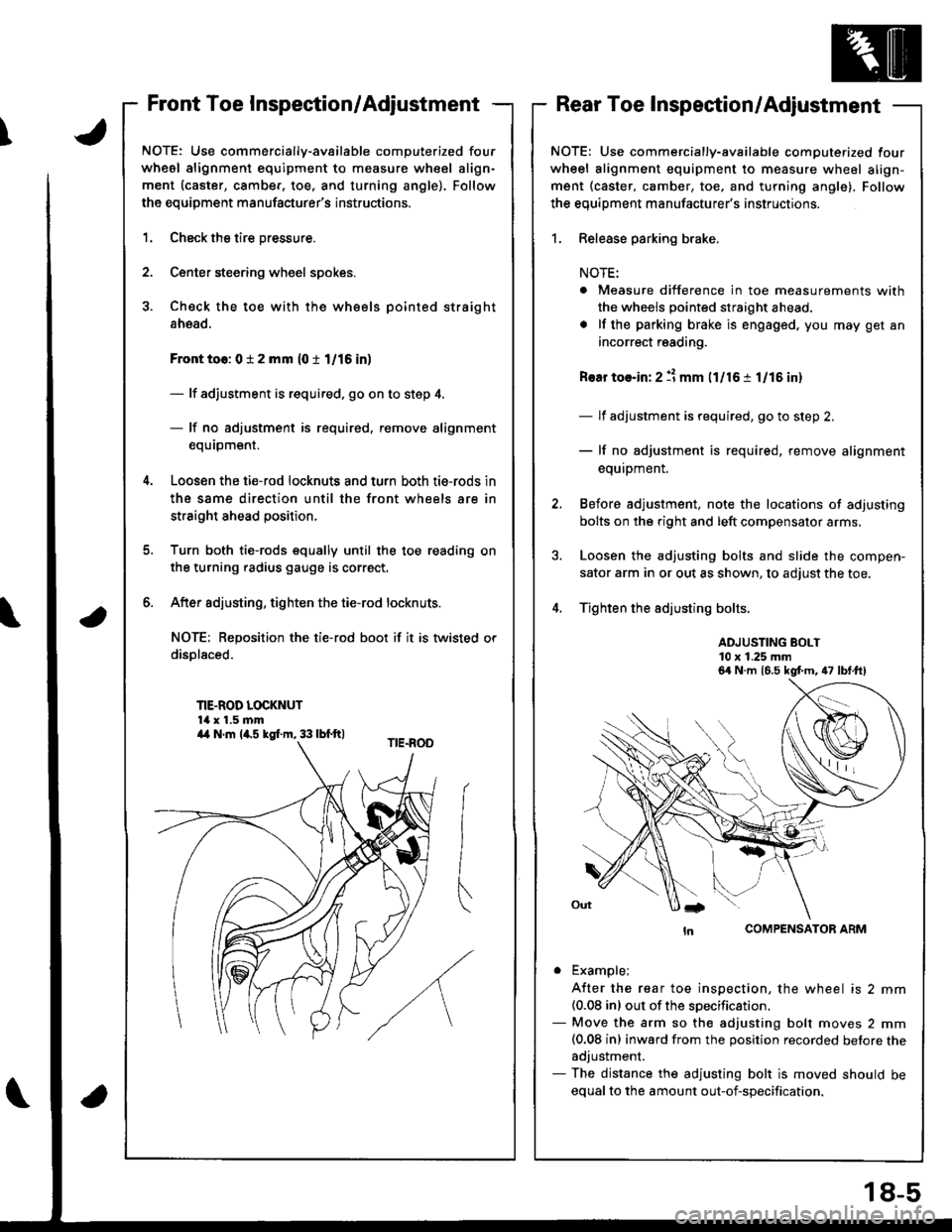
Loosen the ti€-rod locknuts and turn both tie-rods in
the same direction until the front wheels are in
straight ahead position.
Turn both tie-rods equally until the toe reading on
the turning radius gauge is correct.
After sdjusting, tighten the tie-rod locknuts.
NOT€: Reposition the tie-rod boot if it is twisted or
displaced.
TIE-ROD LOCKNUT14 x 1.5 mm
6.
a
NOTE: Use commercially-available computerized four
wheel alignment equipment to measure wheel align-
ment (caster, camber, toe, and turning angle), Follow
the equiDment manufacturer's instructions.
1. Release parking brake.
NOTE:
. Measure difference in toe measurements with
the wheels pointed straight ahead.
. lf the parking brake is engaged. you may get an
incorrect reading.
Rear toe-in: 2 11 mm l1l16 i 1/15 in)
- lf adjustment is required, go to step 2.
- lf no adjustment is required, remove alignment
equipment.
Before adjustment, note the locations of adjusting
bolts on the right and left compensator arms.
Loosen the adjusting bolts and slide the compen-
sator arm in or out as shown, to adjust the toe.
Tighten the adjusting bolts.
ADJUSTING BOLT10 x 1.25 mm
COMPENSATOR ARM
. Example;
A{ter the rear toe inspection, the wheel is 2 mm(0.08 inl out of the soecification.- Move the arm so the adjusting bolt moves 2 mm(0.08 inl inward from the position recorded betore theadjustment.- The distance the adjusting bolt is moved should be
equal to the amount out-of-specification.
6a N.m 16.5 kgt m, 47 lbt.ft)
a4 N.m la.s kgI.m, 33 lbf.ft)
18-5
Page 718 of 1681
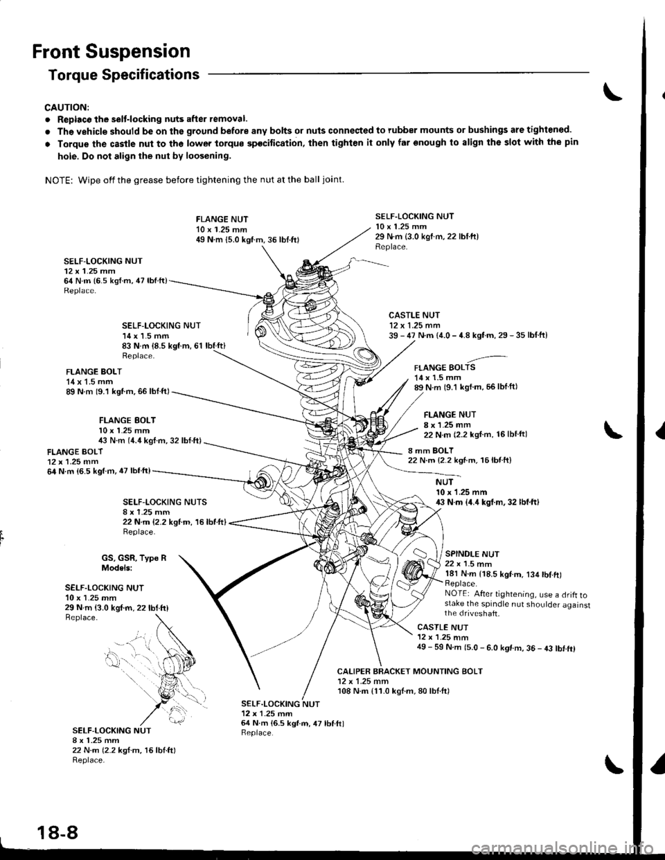
Front Suspension
Torque Specifications
CAUTION:
. Replacc the selt-locking nuts after removal.
. The vehicle should be on the ground before any bolts or nuls connected to rubber mounts or bushings are tightoned.
o Torque thc castle nut to the lower torque spocitication, then tighten it only far onough to align the slot with the pin
hole. Do not align the nut bv loosening.
NOTE: Wipe offthegrease before tightening the nutatthe ball joint.
SELF-LOCKING NUT12 x 1.25 mm64 N.m (6.s ksf.m, 47 lbfft)
FLANGE NUT10 x 1.25 mm49 N.m {5.0 kgtm.36 lbt.frl
SELF.LOCKING NUT10 x 1.25 mm29 N.m {3.0 kgtm,22 lbl.ft)Replace.
CALIPER BRACKET MOUNTING BOLT12 x 1.25 mm108 N.m {11.0 kgl.m,80lbl.ftl
SELF-LOCKING NUT14 x 1.5 mm83 N.m {8.5 kgf.m, 61 lbf.ft}
CASTLE NUT12 x 1.25 mm39 - 47 N.m {4.0 - 4.8 kgtm, 29 - 35 lbf.ft}
-'-FLANGE BOLTS14 x 1.5 mm89 N.m (9.1 kgl m, 56lblft)
FLANGE NUT8 x 1.25 mm22 N.m (2.2 kgf.m, 16lbtftl
8 mm BOLT22 N.m {2.2 ksnm, 16lb{ ft}
Replace.
FLANGE BOLT14 x 1.5 mm89 N m 19.1 kgt.m,66 lbl.ftl
FLANGE EOLTl0 x l�25 mm4i, N.m (4.4 kgl.m, 32 lbf.ft)
FLANGE BOLT12x 1.25 mm64 N.m (6.5 kgtm, iU lbfftl
SELF-I-OCKING NUTS
22 N.m {2.2 kgtm, 16lbtftlReplace.
NUT10 x 1.25 mm43 N.m {4.4 kgt.m,32 lbf.ftl
SPINDLE NUT22 x 1.5 nm181 N.m {18.5 kgtm. 134 tbl.ft)Replace.NOTEi After tightening, use a drifl tostake the spindle nut shoulder againstthe dfiveshaft,29 N.m {3.0 kgf.m, 22lbtttlBeplace.
GS, GSR, Type RModels:
SELF.LOCKING NUT10 x 1.25 mm
SELF-LOCKING NUTI x 1.25 mm22 N.m (2.2 ksf.m, 16lbl.ftlReplace-
CASTLE NUT12 x '1.25 mm49 - 59 N.m (5.0 - 6.0 kgt m, 36 - 43 tbt.ftl
SELF.LOCKING NUT12x 1-25 tnrn64 N.m 16.5 kgl.m, 47 lbf.ftlReplace.
- --.." t,..
0-. .
18-8
Page 720 of 1681
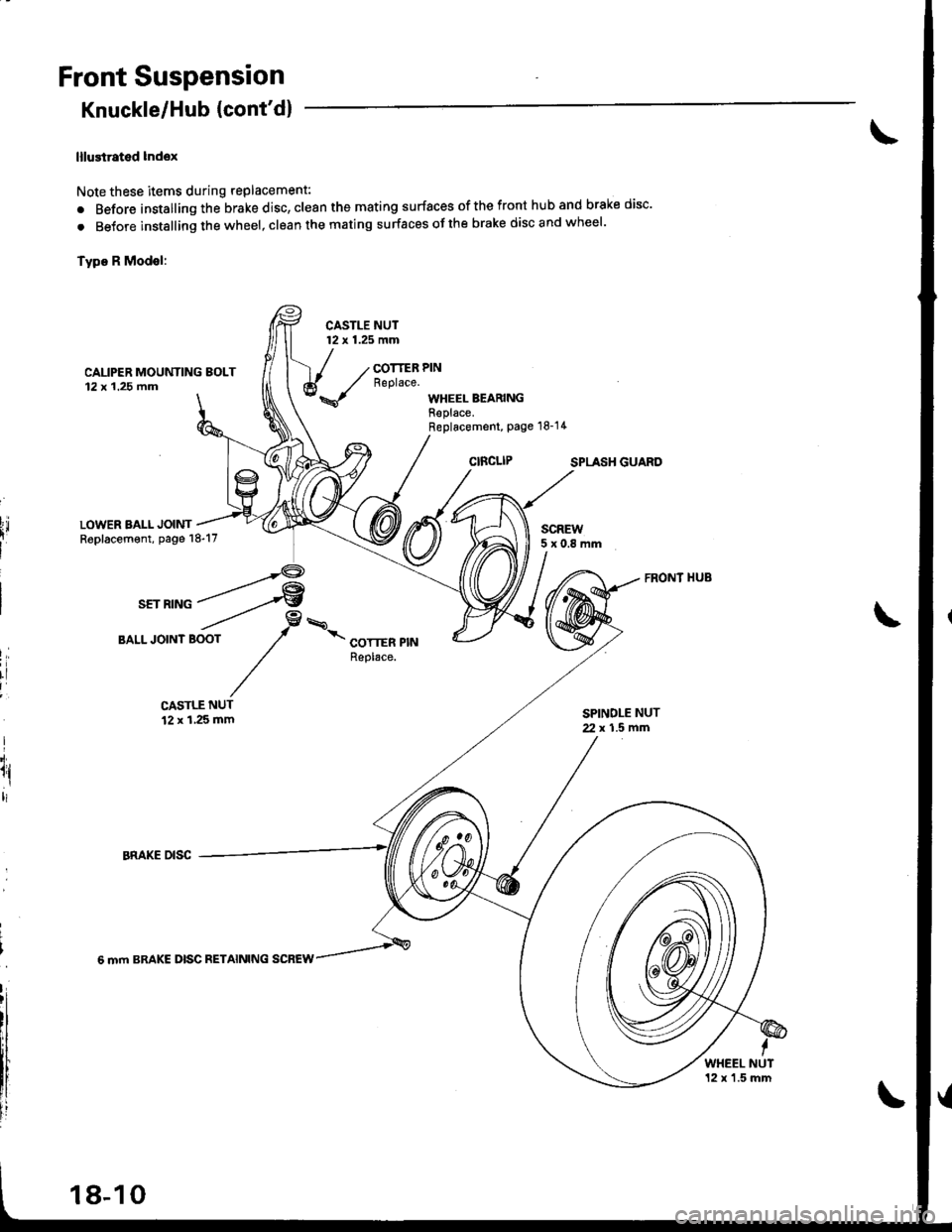
Front Suspension
Knuckle/Hub {cont'd}
lllustrated lndox
Note these items during replacement:
. Before installing the brake disc, clean the mating surfaces of the front hub and brake disc'
. BeJore instslling the wheel, clean the mating surfaces ofthe brake disc and wheel'
Type R Modsl:
CASTLE NUT12 x 1.25 mm
CAUPER MOUNTING EOLT12x 1.25 fim
COTTER PINReplace.
WHEEL BEARINGReplace.Replacement, Page 18-14
SPLASH GUARO
LOWER BALL JOINTReplacement, page 18-17SCREW5x0.8mm
I,
rl
I
I'i.
1l,ltl
CASTLE NUT12 x 1,25 mmSPINDLE NUT2. x 1.5 mfi
6 mm BRAKE DISC RETAINING SCREW
WHEEL NUT12 x'1.5 mm
18-10