Mount HONDA INTEGRA 1998 4.G Owner's Guide
[x] Cancel search | Manufacturer: HONDA, Model Year: 1998, Model line: INTEGRA, Model: HONDA INTEGRA 1998 4.GPages: 1681, PDF Size: 54.22 MB
Page 417 of 1681
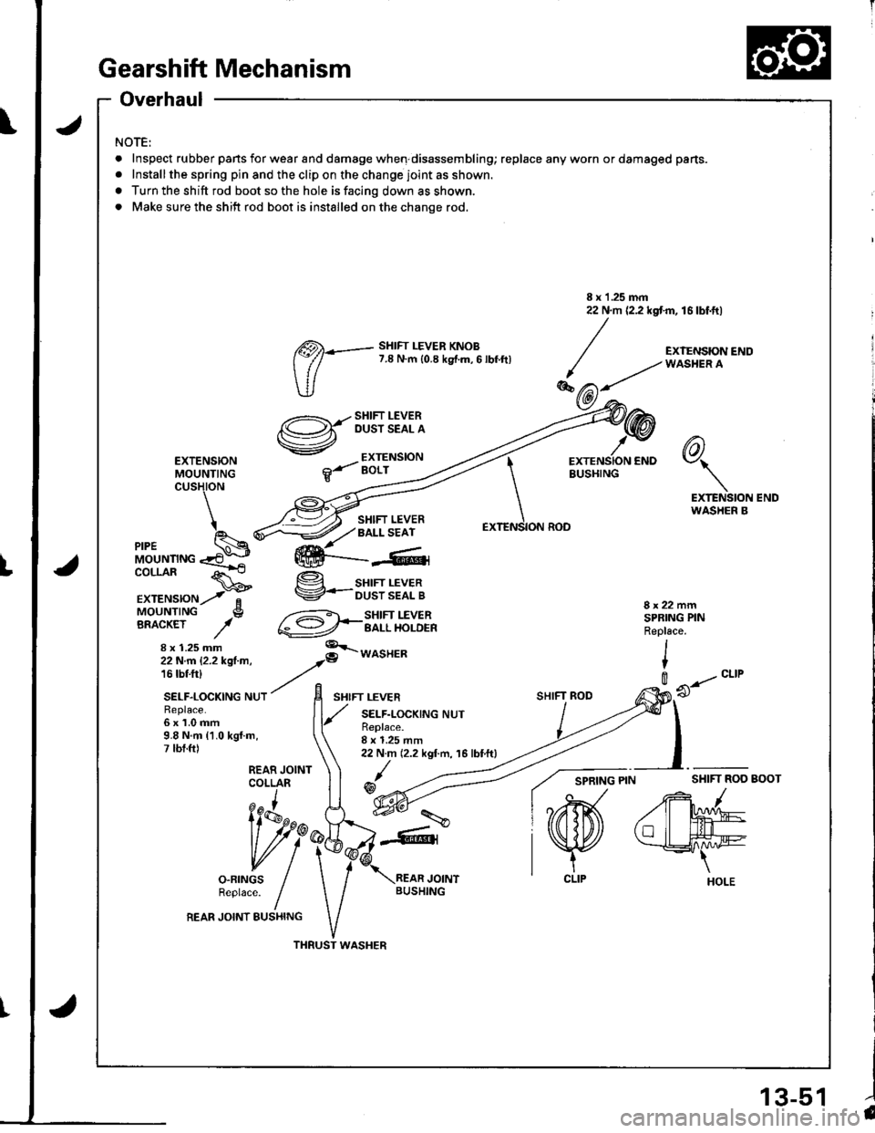
Gearshift Mechanism
Overhaul
NOTE:
.Inspe(
.lnstall
a Turn t
. Make
Inspect rubber pans for wear and damage when disassembling; replace any worn or damaged pans.
Installthe spring pin and the clip on the change joint as shown.
Turn the shift rod boot so the hole is facing down as shown.
Make sure the shift rod boot is installed on the change rod.
\
tu
<:;s\-
-,-"Ye/
R€place.6x1.0mm9.8 N.m {1.0 kgl.m,7 lbt.ft)
liAru^
vll
o-FTNGS /Reptace. fREAR JOINT EUSHING
I x 1 .25 mm22 N.m {2.2 kgt m, 16 lbf.ft)
EXTENSIONMOUNTINGcusHtoN
6)\7\
EXTENSION ENDWASHER B
MOUNTINGCOLLAR
EXTENSIONMOUNTINGBRACKET
x 1.25 mm
SHIFT LEVERBALL SEAT
g sHrFr LEVERV-ousrssflg
@*3li.T'lib'l'
8x22mmSPBING PINRepl6ce.
I
t
SHIFT ROD
0 --..- "ttt
REAR JOINTCOLLARSHIFI ROD BOOT/
/rM
tllL#e
THRUST WASHER
@)*- sHtFr LEVER KNoB
(:// 7.8 N.m {0.8 ks{.m,6 lbf.ftl
SHIFT LEVEROUST SEAL A
EXTENSIONBOLT
8 x 1.25 mm22 N.m (2.2 kgf.m, 16 lbtft)
/@
EXTENSION CNDBUSHING
ION ROD
-\
\
\EXTENS
ffi---4,
l'a13-51
Page 420 of 1681
Description
\J
t{
{
14-3
The automatic transmission is a combination of a 3-element torque converter and triple-shalt electronically controlled
automatic transmission which provides 4 speeds forward and 1 speed reverse. The entire unit is positioned in line with
the engrne.
Torque Converter, Gears, and Clutches
The torque converter consists of a pump, turbine, and stator, assembled in sigle unit. The torque converter is connected to
the engine crankshaft so they turn torether as a unit as the engine turns. Around the outside of the torque convener is a
ring gear which meshes with the starter pinion when the engine is being started. The entire torque converter assembly
serves as a flywheel while transmitting power to the transmission mainshaft.
The transmission has three parallel shafts; the mainshaft. the countershaft, and the sub shaft. The mainshaft is in-line with
the engine crankshaft.
The mainshaft includes the 1st, and 2ndl4th clutches,and gear for 3rd, 2nd, 4th, reverse, and 1st. (3rd gear is integral with
the mainshaft, while reverse gear is integral with the 4th gear.)
The countershaft includes the 3rd clutch and gears for 3rd,2nd, 4th, reverse, 1st, and parking. Reverse and 4th gears can
be loched to the countershaft at its center,providing 4th gear or reverse, depending on which way the selector is moved.
The sub-shaft includes the 1st-hold clutch and gears fo 1st and 4th.
The gears on the mainshaft are in constant mesh with those on the countersahft and sub-shaft.When certain combinations
of gears in the transmission are engaged by clutches. power in transmitted from the mainshaft to the countershaft via the
sub-shaft to orovude oil, lo'1. E, E. and E.
Electronic Control
The electronic control svstem consists of the Transmission Control Module (TCM), sensors, and four solenoid valves.
Shilting and lock-up are electronically controlled for comfortable driving under all conditions.
The TCM is located below the dashboard, behind the lelt side kick panel on the driver's side.
Hydraulic Control
The valve bodies include the main valve body, the secondary valve body, the regulator valve body, the serbvo body, and
the lock-up valve body, through the respective separator plates, They are bolted to the torque converter housing,
The main valve body contains the manual valve, the 1-2 shift valve, the 2-3 shitt valve, the Clutch Pressure Control
lCPC) valve, the 4th exhaust valve, the reliel valve, and the ATF pump gears.
The secondary valve body contains the 4-3 kick-down valve, the 3-2 kick-down valve, the 2-3 orifice control valve, the
3-4 shift valve, the orilice control valve, the modulator valve, and the servo control valve.
The regulator valve body contains the pressure regulator valve, the lock-up control valve, the torque converter check
valve, and the cooler check valve.
The servo body contains the servo valve, which is integrated with shift fork shaft, the throttle valve B, and the accumula-
tors.
The lock-up valve body contains the lock-up shift valve and the lock-up timing B valve, and is bolted to the regulator valve
ooqy.
Fluid from the regulator passes through the manual valve to the various control valves.
Shift Control Mechanism
Input to the TCM from various sensors located throughout the car determines which shift control solenoid valve should
be activated. Activating a shitt control solenoid valve changes modulator pressure, causing a shift valve to move. This
pressurizes a line to one ol the clutches, engaging that clutch and its corresponding gear.
Lock-uD Mechanism
In @ position, in 2nd, 3rd and 4th, and @ position in 3rd, pressurized fluid can be drained lrom the back oI the tor-
que converter through a fluid passage, causing the lock-up piston to be held against the torque converter cover. As this
takes place, the mainshaft rotates at the same speed as the engine crankshaft. Together with hydraulic control, the TCM
optimizes the timing of the lock-up mechanism.
The lock-up valves controlthe range of lock-up according to lock-up control solenoid valves A and B, and throttle valve B.
When lock-up control solenoid valves A and B activate, modulator pressure changes. Lock-up control solenoid valves
A and B are mounted on the torque converter housing, and are controlled by the TCM.
(cont'd)
Page 423 of 1681
Description
Clutches
t
{
The four-speed automatic transmission uses hydraulically-actuated clutches to engage or disengage the transmission gears.
When hydraulic pressure is introduced into the clutch drum. the clutch piston is applied. This presses the friction discs
and steel plates together, locking them so they don't slip. Power is then transmitted through the engaged clutch pack
to its hub-mounted gear.
Likewise, when hydraulic pressure is bled from the clutch pack, the piston releases the friction discs and steel plates,
and they are free to slide past each other while disengaged. This allows the gear to spin independently on its shaft, trans-
mrrrng no power.
lsr Clutch
The 1 st clutch engages/disengages 1st gear, and is located at the end of the msinshaft, just behind the right side cover.
The 1st clutch is supplied hydraulic pressure by its ATF feed pipe within the mainshaft.
l st-hold clurch
The '1 st-hold clutch engages/disengages 'lst-hold or E] position, and is located at the middle of the sub-shaft. The 1st-
hold clutch is supplied hydraulic pressure by its ATF feed pipe within the sub-shaft.
2nd Clutch
The 2nd clutch engages/disengages 2nd gear, and is located at the middle of the mainshaft. The 2nd clutch is joined
back-to-back to the 4th clutch. The 2nd clutch is supplied hydraulic pressure through the mainshaft by a circuit connected
to the internal hydraulic circuit.
3rd ClutchThe 3rd clutch engages/disengages 3rd gear, and is located at the end of the counte.shaft, opposite the right side cover.
The 3rd clutch is supplied hydraulic pressure by its ATF feed pipe within the countershaft.
4th Clutch
The 4th clutch engages/disengages 4th gear, as well as reverse gear, and is located at the middle of the mainshaft.
The 4th clutch is joined back-to-back to the 2nd clutch. The 4th clutch is supplied hydraulic pressure by its ATF feed
oiDe within the mainshaft.
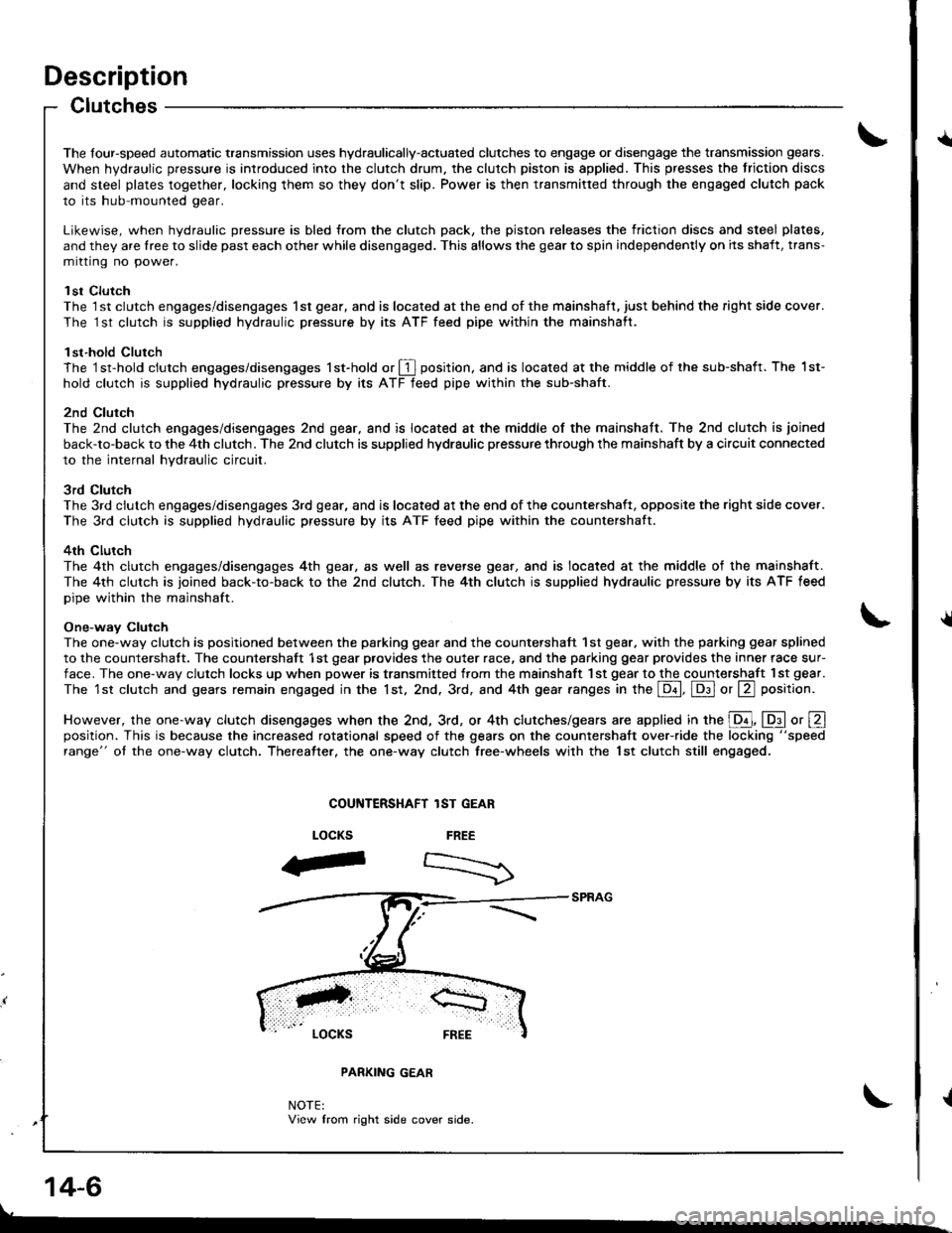
One-way Clutch
The one-way clutch is positioned between the parking gear and the countershaft 1st gear. with the parking gear splined
to the countershalt. The countershaft 1st gear provides the outer race, and the parking gear provides the inner race sur-
face. The one-way clutch locks up when power is transmitted from the msinshaft 1st gear to the countershaft I st gear.
The 1st clutch and gears remain engaged in the 1st, 2nd. 3rd, and 4th gear ranges in the Lqd, Lq9.l or La position.
However, the one-way clutch disengages when the 2nd, 3rd, or 4th clutches/gears are applied in the E, lDll o, Eposition. This is because the increased rotational speed of the gears on the countershatt over-ride the locking "speed
range" ot the one-way clutch. Thereatter, the one-way clutch free-wheels with the lst clutch still engaged.
COUiITERSHAFT lST GEAR
FREE
-".--)
LOCKS
F
LOCKS FREE
PARKING GEAR
NOTE:View from right side cover side.
14-6
Page 442 of 1681
I
I
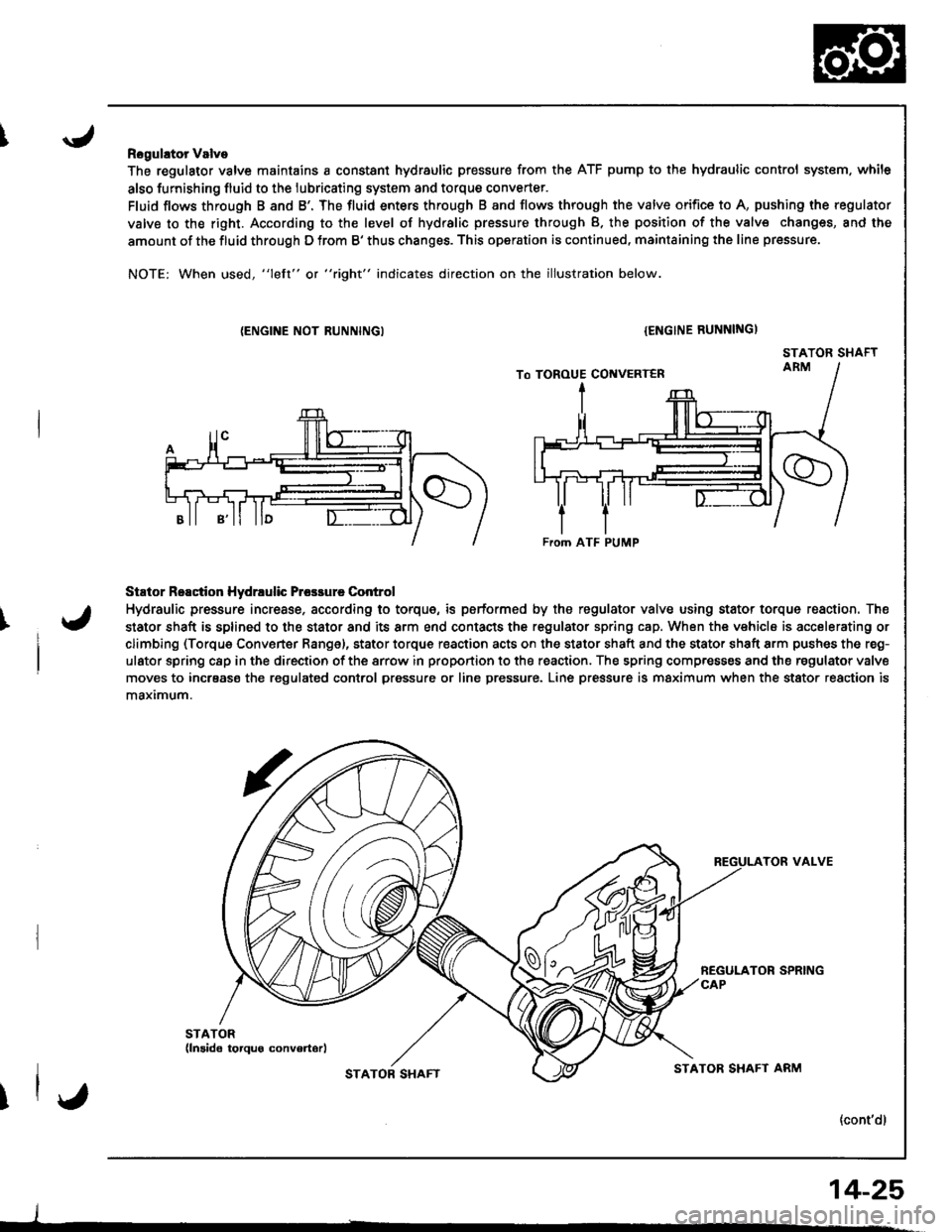
Rogulator Valve
The regulator valve maintains a constant hydraulic pressure from the ATF pump to the hydraulic control system. while
also furnishing fluid to the lubricating system and torque converter.
Fluid flows through B and B'. The fluid enters through B and flows through the valve orifice to A, pushing the regulator
valve to the right. According to the level of hydralic pressure through B. the position of the valv€ changes, and the
amount of the fluid through D from B' thus changes. This operation is continued, maintaining the line pressure.
NOTE: When used, "left" or "right" indicates direction on the illustration below.
{ENGINE NOT RUNNINGI{ENGINE RUNNINGI
STATOR SHAFT
Stator Reactior Hydrrulic Prcsrure Control
Hydraulic pressure incresse, according to torque, is performed by the regulator valve using stator torque reaction. The
stator shaft is splined to the stator and its arm end contacts the regulator spring cap. When the vehicle is accelerating or
climbing (Torque Converter Range), stator torque reaction acts on the stator shaft and the stator shaft arm pushes the reg-
ulator spring c8p in the direction of the srrow in proportion to the reaction. The spring compresses and the regulator valve
moves to incrsase the regulated conlrol pressure or line pressure. Line pressure is maximum when the stator reaction is
maximum.
TOR VALVE
{cont'dl
From ATF PUMP
I
STATOB SHAFTSTATOR SHAFT ARM
14-25
Page 456 of 1681
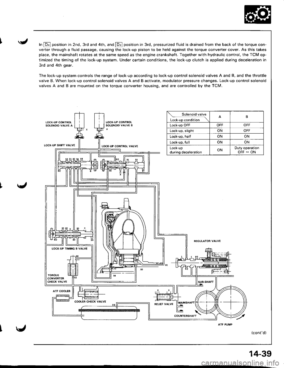
In E position in 2nd, 3rd and 4th, and E position in 3rd, pressurized fluid is drained from rhe back of the torque con-
verter through a fluid passage, causing the lock-up piston to be held against the torque converter cover. As this takes
place, the mainshaft rotates at the same speed as the engine crankshatt. Together with hydraulic control, the TCM op-
timized the timing of the lock-up system. Under certain conditions, the lock-up clutch is applied during deceleration in
3rd and 4th gear.
The lock-up system controls the range of lock-up according to lock-up control solenoid valves A and B, and the throttle
valve B. When lock-up control solenoid valves A and B activate, modulator pressure changes. Lock-up control solenoid
valves A and B are mounted on the torque converter housing. and are controlled by the TCM.
LOCK,UP CONTROL
LOCT.UP SHIfT VALVE
AlF COOIER
tocK uP coNTno! valvE
Solenoid valve
L*r""r "o.Jtio" \B
Lock'up OFFOFFOFF
Lock-up, slightONOFF
Lock-up, halfONON
Lock-up, fullONON
LOCK-Updu.ing decelerationONDuty operationOFF - ON
IOCK UP TIMING B VATVE
(cont'd)
14-39
Page 459 of 1681
Description
I,OCK UP SHIFT VALVE
Lock-up System (cont'dl
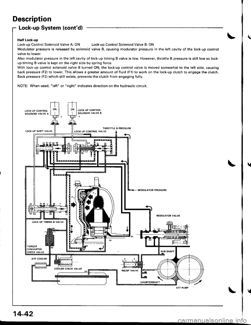
Halt Lock-up
Lock-up Control Solenoid Valve A: ONLock-up Control Solenoid Valve B: ON
Modulator pressure is released by solenoid valve B. causing modulator pressure in the left cavity of the lock-up control
valve to lower.
Also modulator pressure in the left cavity of lock-up timing B valve is low. However, throttle B pressure is still low so lock-
up timing B valve is kept on the right side by spring force.
With lock-up control solenoid valve B turned ON, the lock-up control valve is moved somewhat to the left side, causing
back pressure (F2) to lower. This allows a greater amount of fluid (F1) to work on the lock-up clutch to engage the clutch.
Back pressure (F2) which still exists, prevents the clutch from engaging fully.
NOTE: When used, "|eft" or "right" indicates direction on the hydraulic circuit.
LOCK.UP COI\ITBOL
THROITIE B PRESSUREIOCX UP COIITROL VALVE
MODULATOR PNESSURE
TOCK UP TIMING B VALVE
14-42
\
t
{
Page 504 of 1681
Replacement
(.
L
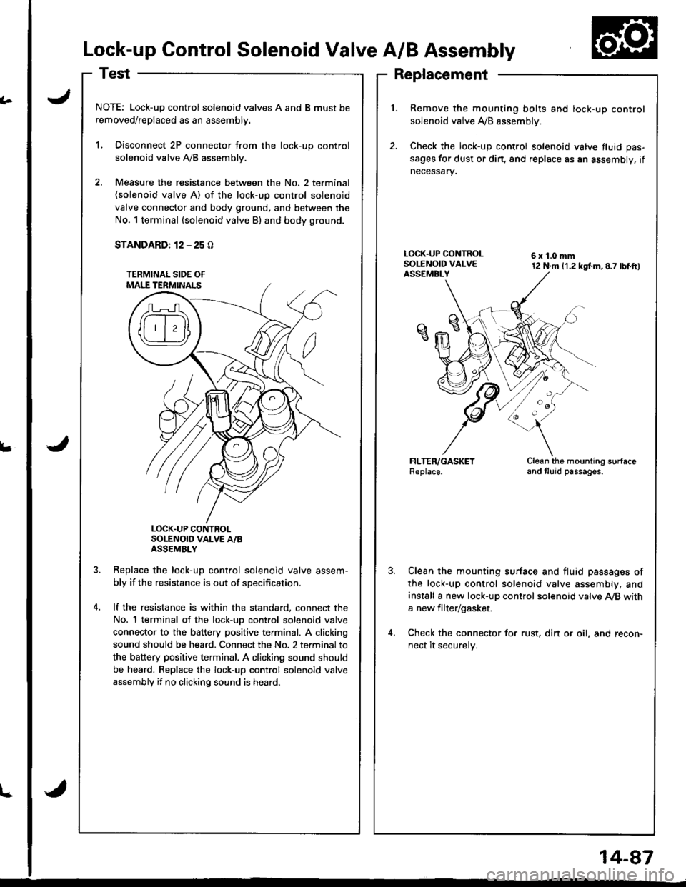
Lock-up Control Solenoid Valve A/B Assembly
NOTE: Lock-up control solenoid valves A and B must be
removed/replaced as an assembly.
L Disconnect 2P connector from the lock-up control
solenoid valve Ay'B assembly.
2. Measure the resistance between the No. 2 terminal
{solenoid valve A) of the lock-up control solenoid
valve connector and body ground, and between the
No. 1 terminal {solenoid valve B) and body ground.
STANDARD: 12 - 25 O
LOCK.UP CONTROLSOLENOID VALVE A/BASSEMBLY
Replace the lock-uo control solenoid valve assem-
bly if the resistance is out of specification.
lf the resistance is within the standard, connect the
No. 1 terminal of the lock-uD control solenoid valve
connector to the battery positive terminal. A clicking
sound should be hea.d. Connect the No. 2 terminal to
the battery positive terminal. A clicking sound should
be heard. Replace the lock-up control solenoid valve
assembly if no clicking sound is heard.
1.Remove the mounting bolts and lock-up control
solenoid valve A/B assemblv.
Check the lock-up control solenoid valve fluid pas-
sages for dust or dirt. and replace as an assembly, if
necessary.
6x1.0mm12 N.m (1.2 kgtm,8.7 lbf.ftl
Clean the mounting surfaceand tluid passages.
Clean the mounting surface and fluid passages of
the lock-up control solenoid valve assembly, and
install a new lock-up control solenoid valve Ay'B with
a new filter/gasket.
Check the connector for rust, din or oil, and recon-
nect it securelv.
l-
14-87
Page 505 of 1681
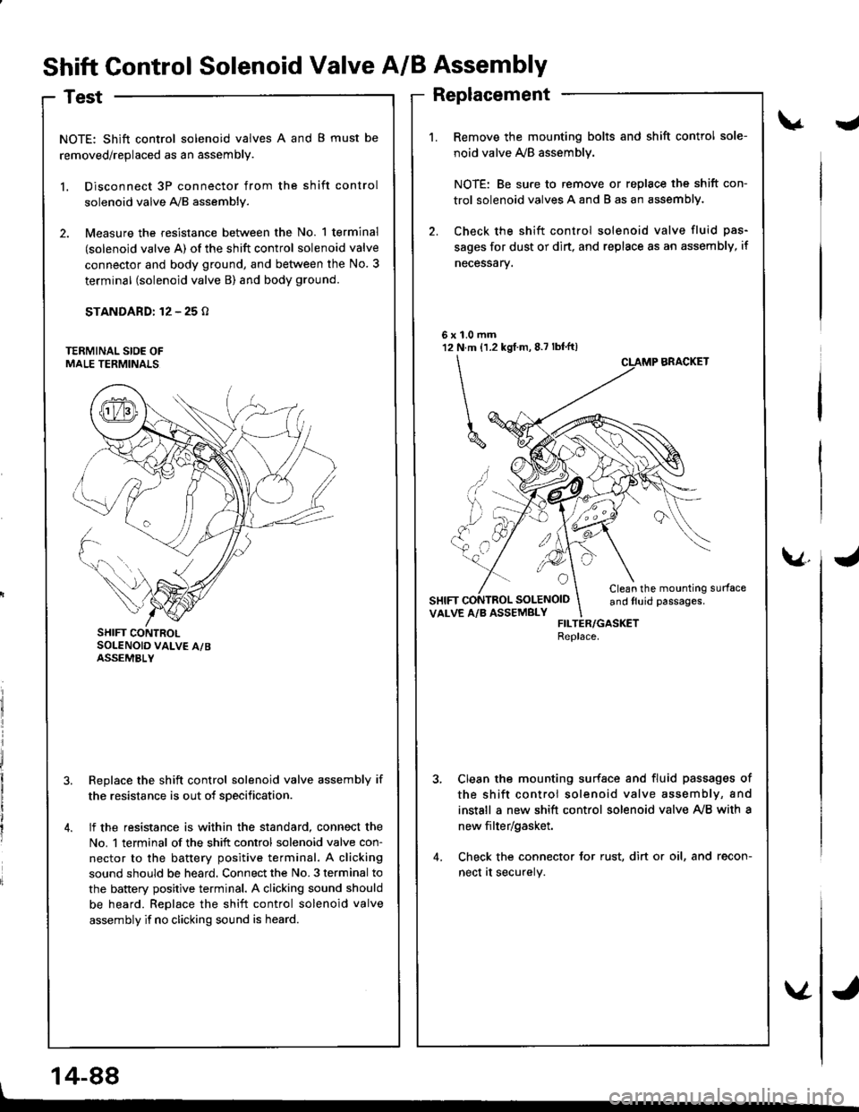
Shift Control Solenoid Valve A/B Assembly
Test
NOTE: Shift control solenoid valves A and B must be
removed/replaced as an assembly.
l. Disconnect 3P connector from the shift control
solenoid valve A,/B assembly.
2. Measure the resistance between the No. 1 terminal
(solenoid valve A) of the shift control solenoid valve
connector and body ground, and between the No. 3
terminal (solenoid valve B) and body ground.
STANDARD: 12 - 25 o
Replace the shift control solenoid valve assembly if
the resistance is out of sDecification.
lf the resistance is within the standard, connect the
No. 1 terminal of the shift control solenoid valve con-
nector to the battery positive terminal. A clicking
sound should be heard. Connect the No. 3 terminal to
the battery positive terminal. A clicking sound should
be heard. Replace the shift control solenoid valve
assembly if no clicking sound is heard.
J
1.0 mmN.m {1.2 kgf m, 8.7 lbf'ft)
\
^ ,, ..,'
UYM
6x't2
a
SOLENOID
v.
SHIFT CONTROLSOLENOID VALV€ A/BASSEMBLY
Replacement
Remove the mounting bolts and shift control sole-
noid valve ly'B assemblv.
NOTE: Be sure to remove or replace the shift con-
trol solenoid valves A and B as an assemblY.
Check the shift control solenoid valve fluid pas-
sages for dust or dirt, and replsce as an assembly, if
necessarv.
BRACKET
Clean the mounting surfaceand tluid passages.VALVE A/B ASSEMBLYFILTER/GASKETReplace.
Clean the mounting surfsce and fluid passages of
the shift control solenoid valve assembly, and
install a new shift control solenoid valve Ay'B with a
new filter/gasket.
Check the connector for rust, dirt or oil, and recon-
nect at securely.
14-88
Page 510 of 1681
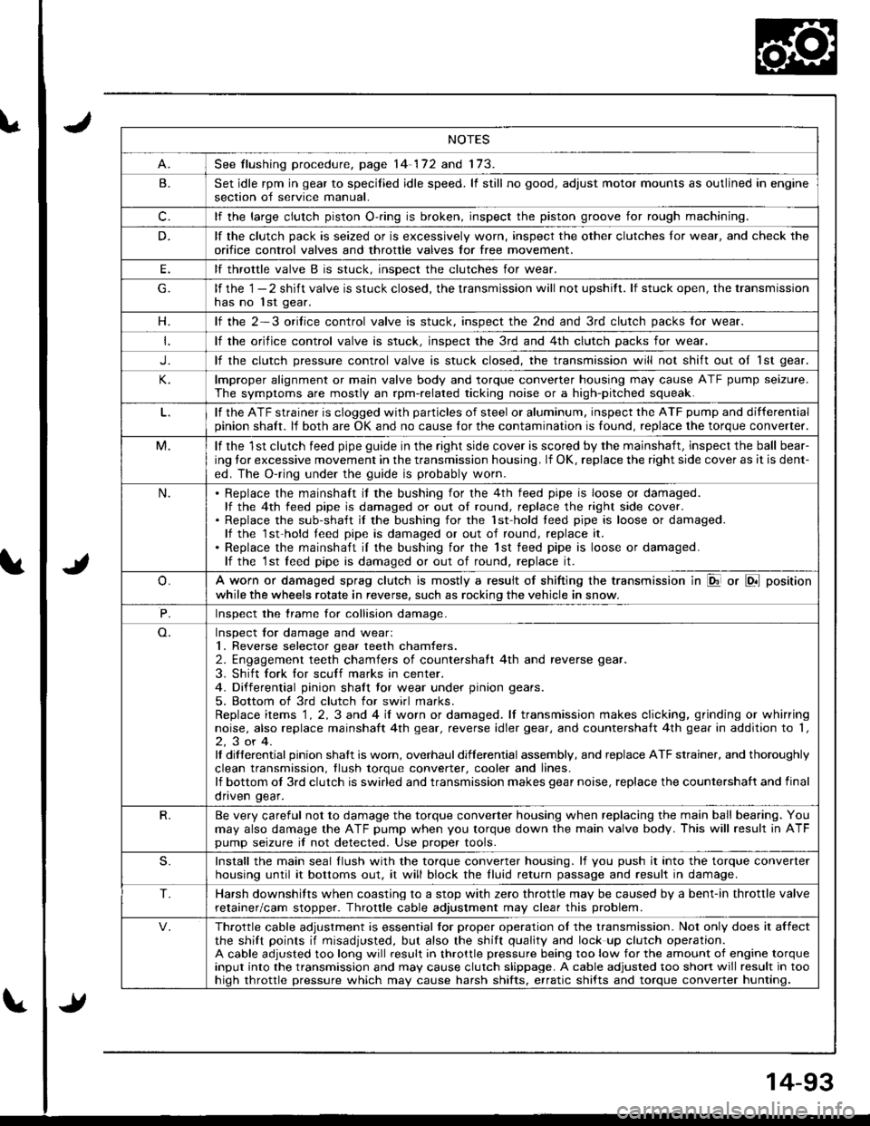
NOTES
See flushing procedure, page 14-172 and 173.
B.Set idle rpm in gear to specilied idle speed. lf still no good, adjust motor mounts as outlined in enginesection of service manual.
c.lf the large clutch piston O-.ing is broken, inspect the piston groove for rough machining.
D.lf the clutch pack is seized or is excessively worn, inspect the other clutches lor wear, and check the
orifice control valves and throttle valves for free mov€ment.
E.lf throttle valve B is stuck. insDect the clutches for wear.
lf the 1 - 2 shift valve is stuck closed, the transmission will not upshitt. lf stuck open, the transmissionhas no lst gear.
H.lf the 2-3 orilice control valve is stuck, inspect the 2nd and 3rd clutch packs for wear.
lf the orifice control valve is stuck. inspect the 3rd and 4th clutch packs for wear.
J.lf the clutch pressure control valve is stuck closed, the transmission will not shift out oI 1st gear.
lmproper alignment or main valve body and torque converter housing may cause ATF pump seizure.
The symptoms are mostly an rpm-related ticking noise or a high-pitched squeak.
lf the ATF strainer is clogged with particles of steel or aluminum, inspect the ATF pump and differentialpinion shaft. lf both are OK and no cause for the contamination is found, replace the torque converter.
M.lf the 1st clutch feed pipe guide in the right side cover is scored by the mainshaft, inspect the ball bear-
ing lor excessive movement in the transmission housing. lf OK, replace the right side cover as it is dent-
ed. The O-ring under the guide is probably worn.
N.Replace the mainshaft if the bushing for the 4th feed pipe is loose or damaged.lf the 4th feed pipe is damaged or out of round, replace the right side cover.Replace the sub-shaft il the bushing for the 1st-hold teed pipe is loose or damaged.lf the 1st-hold teed pipe is damaged or out of round, replace it.
Replace the mainshaft iI the bushing for the lst feed pipe is loose or damaged.lf the 1st leed pipe is damaged or out of round, replace it.
A worn or damaged sprag clutch is mostly a result of shifting the transmission in El or LDll position
while the wheels rotate in reverse, such as rocking the vehicle in snow.
P.Inspect the trame for collision damage.
Inspect lor damage and wear:1. Reverse selector gear teeth chamfers.2. Engagement teeth chamfers of countershaft 4th and reverse gear.
3. Shift fork for scuff marks in center.4. Differential pinion shaft tor wear under pinion gears.
5. Bottom of 3rd clutch for swirl marks.Replace items 1 . 2, 3 and 4 iI worn or damaged. lf transmission makes clicking, grinding or whirringnoise, also replace mainshaft 4th gear, reverse idler gear, and countershatt 4th gear in addition to '1,
2,3or4.It differential pinion shalt is worn, overhaul differential assembly, and replace ATF strainer, and thoroughly
clean transmission, tlush torque conveder, cooler and lines.lf bottom ot 3rd clutch is swirled and transmission makes gear noise, replace the countershaft and final
onven qear.
R.Be very careful not to damage the torque converter housing when replacing the main ball bearing. You
may also damage the ATF pump when you torque down the main valve body. This will result in ATFpump seizure if not detected. Use proper tools.
S.Install the main seal llush with the torque converter housing. lf you push it into the torque converterhousing until it bottoms out. it will block the fluid return passage and result in damage.
T.Harsh downshifts when coasting to a stop with zero throttle may be caused by a bent-in throttle valve
retainer/cam stopper. Throttle cable adjustment may clear this problem.
Throttle cable adjustment is essential tor proper operation ol the transmission. Not only does it affectthe shift points if misadjusted, but also the shift quality and lock up clutch operation.A cable adjusted too long will result in throttle pressure being too low for the amount of engine torqueinput into the transmission and may cause clutch slippage. A cable adjusted too short will result in toohiqh throttle pressure which may cause harsh shifts, erratic shifts and torque converter hunting.
Page 522 of 1681
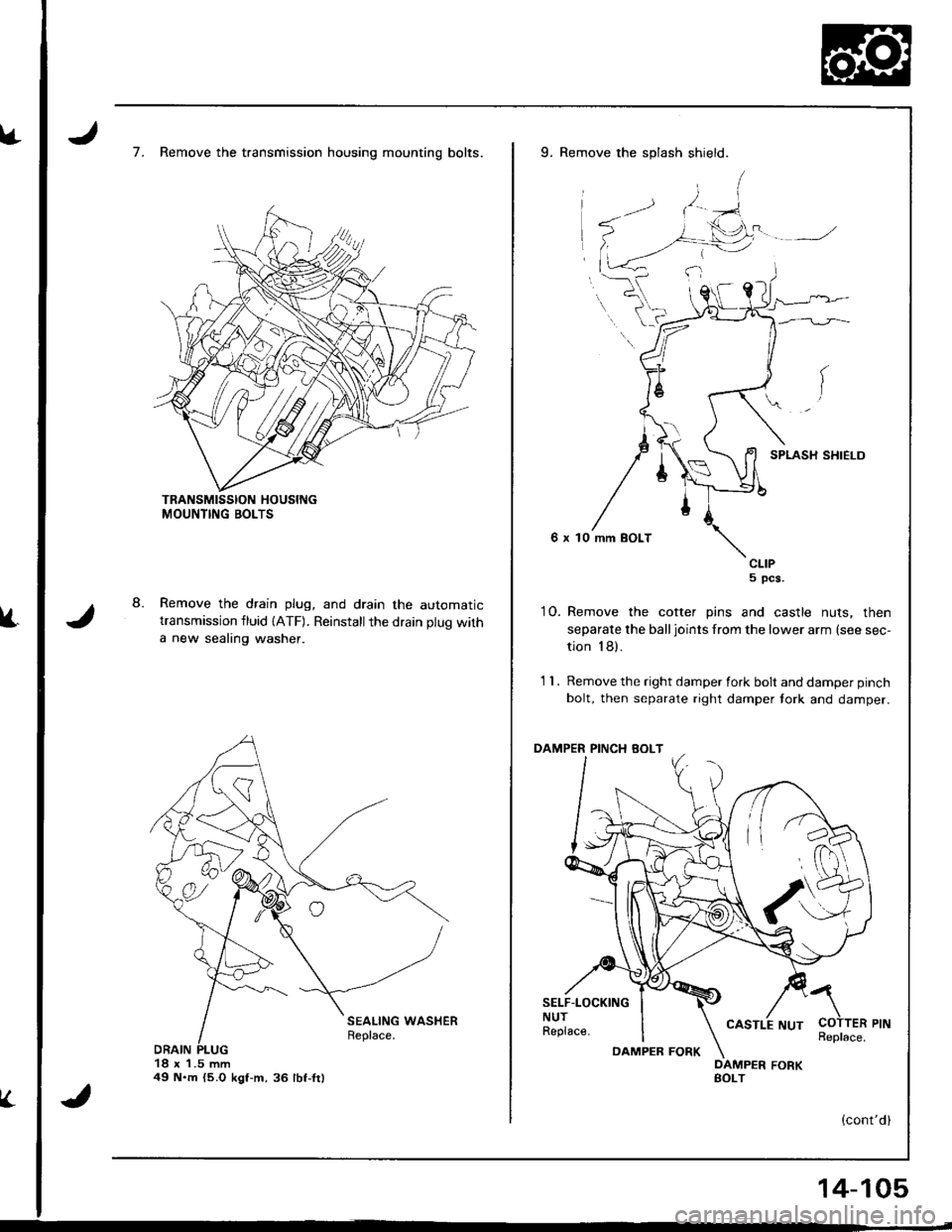
8.
7. Remove the transmission housing mounting bolts.
Remove the drain plug, and drain the automatictransmission fluid {ATF). Reinstallthe drain plug with
a new sealing washer.
18 x 1.5 mm49 N.m {5.O kgt-m,36 lbf-fr)
V.
9. Remove the splash shield.
SPLASH SHIELD
6 x 10 mm BOLT
CLIP5 pcs.
10. Remove the cotter pins and castle nuts, then
separate the balljoints from the lower arm (see sec-
tion 18).
1 1 . Remove the right damper fork bolt and damper pinch
bolt, then separate right damper tork and damper.
PINCH BOLT
SELF.LOCKINGNUTReplace.
a
COTTER PINReplace.DAMPEB FORK
14-105