Mount HONDA INTEGRA 1998 4.G User Guide
[x] Cancel search | Manufacturer: HONDA, Model Year: 1998, Model line: INTEGRA, Model: HONDA INTEGRA 1998 4.GPages: 1681, PDF Size: 54.22 MB
Page 205 of 1681
Inspection
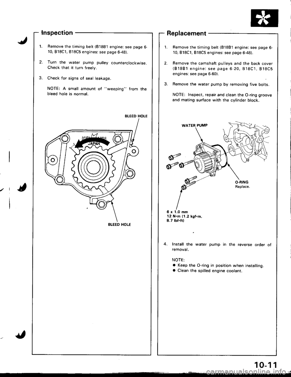
Remove the timing belt (81881 engine: see page 6-10, B'l8Cl,818C5 engines: see page 6-48).
Tu.n the water pump pulley counterclockwise.Check that it turn freely.
Check for sign6 of seal leakage.
NOTE: A small amount of "weeping" trom thebleed hole is normal.
BLEED HOLE
Remove the timing belt (81881 engine: see page 6-
10,818C1, Bl8C5 engines: see page 6-48).
Remove the camshaft pulleys and the back cover(B'1881 engine: see page 6-20, 818C1, 818C5
engines: see page 6-60).
Remove the water pump by removing flve bolts.
NOTE: Inspect, repair and clean the O-ring groove
and mating surface with the cylinder block,
Replacement
6 x 1.0 mm12 N.m 11.2 kgt.m,8.7 tbf.tt)
4. Install the water pump in the reverse order ofremoval.
a Keep the O-ring in position when installing.a Clean the spilled engine coolant.
BLEED HOL€
10-1 1
Page 242 of 1681
ECM Data
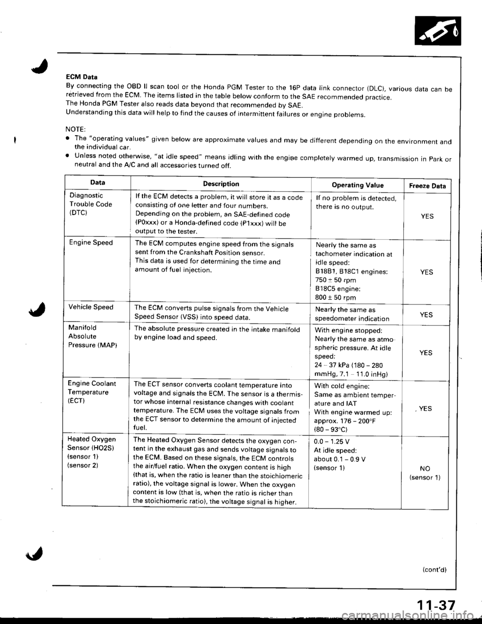
By connecting the OBD ll scan tool or the Honda PGM Tester to the 16P data link connector (DLC), various data can beretrieved from the EcM The items risted in the tabre berow conform to the sAE recommended practice.The Honda PGM Tester also reads data beyond that recommended bv SAE.understanding this data wirl herp to rind the causes of intermiftent fairures or engine probrems.
NOTE:
' The "operatlng values" given below are approximate values and may be different depending on the environment andthe individual car.' Unless noted otherwise, "at idle speed" means idling with the engiFe completely warmed up, transmissron in park orneutral and the A,/C and all accessories turned off.
DataDescriptionOperating ValueFreeze Data
Diagnostic
Trouble Code(DTC)
lf the ECM detects a problem, it will store tt as a cocteconsisting ot one letter and four numbers.Depending on the problem, an SAE-defined code{Poxxx) or a Honda-defined code (plxxx) will beoutput to the lester.
lf no problem is detected,
there is no output.
YES
Engine SpeedThe ECM computes engine speed from the signalssent from the Crankshaft Position sensor.This data is used for determining the I|me andamount of fuel injection.
Nearly the same as
tachometer indication at
idle speed:
81881,818C1 engines:
750 t 50 rpm
818C5 engine:
800 1 50 rpm
YES
Vehicle SpeedThe ECM converts pulse signals trom the VehicleSpeed Sensor (VSS) into speed data.
Nearly the same as
speedometer indicationYES
Manitold
Absolute
Pressure {MAP)
The absolute pressure created in the intake manifoldby engine load and speed.With engine stopped:
Nearly the same as atmo
spheric pressure. At idle
speed:
24 - 37 kPa (180 - 280
mmHg,7.1 1'1.0 inHg)
YES
Engine Coolant
Temperature
(ECT)
The ECT sensor converts coolant temperature intovoltage and signals the ECM. The sensor is a thermis-tor whose internal resistance changes with coolanttemperature. The ECM uses the voltage signals fromlhe ECT sensor to determine the amount of iniectedfuel.
With cold engine:
Same as ambient temper
ature and IAT
With engine warmed up:
approx. 176 - 200'F
{80 - 93.C)
, YES
Heated Oxygen
Sensor (HO2S)
{sensor 1)(sensor 2)
The Heated Oxygen Sensor detects the oxygen con-tent in the exhaust gas and sends voltage signals tothe ECM. Based on these signals,lhe ECM controlsthe airlfuel ratio. When the oxygen content is high{that is, when the ratio is leaner than the stoichiomericratio), the voltage signal is lower. When the oxygencontent is low (that is, when the ratio is richer thanthe stoichiomeric ratio), the voltage signal is higher.
0.0 - 1.25 V
At idle speed:
abour 0.'1 - 0.9 V(sensor I )NO(sensor 1)
(conl'd)
11-37
Page 243 of 1681
Troubleshooting
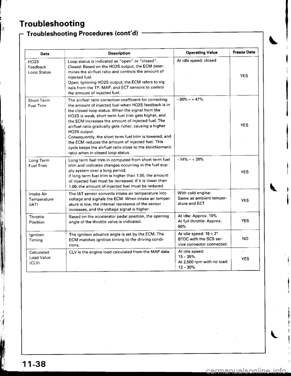
DataDescriotionOperating ValueFreeze Data
HO25
Feedback
Loop Status
Loop status is indicated as "open" or "closed".
Closed: Based on the H02S output, the ECM deter-
mines the airlfuel ratio and controis the amount of
iniected fuel.
Open: lgnoring HO2S output, the ECM refers to sig-
nals from the TP, MAP, and ECT sensors to control
the amount of iniected fuel.
Al idle speed: closed
YES
Short Term
Fuel Trim
The airlfuel ratio correclion coeificient lor correcting
the amount ol iniected fuel when HO2S feedback is in
the closed loop status. When the signal from the
HO2S is weak, short term fuel trim gets highef. and
the ECM increases the amount of injected fuel The
airlfuel ratio gradually gets richer, causing a higher
HO2S output.
Consequentlv, the short term fuel trim is lowered, and
the ECM reduces the amount of injected tuel. This
cycle keeps the airlfuel ratio close to the stoichiomeric
ratio when in closed loop status.
-30o/" - + 41%
YES
Term
Trim
Long
F uel
Long term fuel trim in computed trom short term fuel
trim and indicates changes occurring in the fuel sup-
ply system over a long period.
lf long term fuel trim is higher than 1.00, the amou nt
of injected fuel must be increased. ll it is lower than
1.00, the amount of iniected fuel must be reduced
-14% - + 2Oo/"
YES
lntake Air
Temperature(rAT)
The IAT sensor converts intake air temperature into
voltage and signals the ECM. When intake air temper-
ature is low, the internal resistance of the sensor
increases, and the voltage signal is higher.
With cold engine:
Same as ambient temPer-
ature and ECTYES
Throttle
Position
Based on the accelerator pedal position. the opening
anole of the throttle valve is indicated.
Ar idle: Approx. 107o
At full throttle: Approx.
90%
YES
lgnition
Timing
The ignition advance angle is set by the ECM. The
EClvl matches ignition timing to the driving condi-
tio ns.
At idle speed: 16 t 2'
BTDC with the SCS ser-
vice connector connected.
NO
Calculated
Load Value
(CLV)
CLV is the engine load calculated from the MAP data.At idle speedi
15 - 35%
At 2,500 rpm with no load:
12 - 30./.
YES
-38
Page 283 of 1681
PGM-FI System
Random Misfire
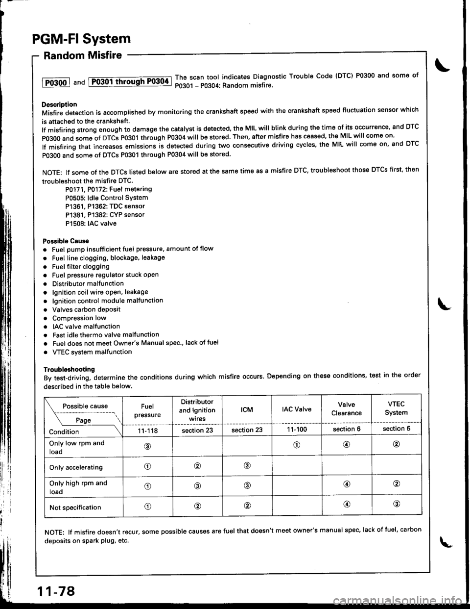
1T0-500 1 a nd Fo-30ittrrousFF0304-lThB scan tool indicates Diagnostic Trouble Code {DTC) P0300 and some of
P0301 - P0304: Random misfire.
Doscription
Misfir; detection is accomplished by monitoring the crankshaft speed with the crankshaft speed fluciuation sensor which
is attached to the crankshsft.
lf misfiring strong enough to damage the catalyst is detected, the MIL will blink during iho time of its occurrence, and DTC
p0300 and some of DTCS p0301 through P0304 will be stor€d. Then, after misfire has ceased, the MIL will come on.
lf misfiring that increases emissions is detected during two consecutive driving cycles, the MIL will come on, and DTC
PO3O0 and some ot DTCS P0301 through P0304 will be stored
NOTE: lJ some of the DTCS listed below are stored at the same time as a misfire DTC, troubleshoot those DTCS first. then
troubleshoot the misfire DTC.
P0171, P0172: Fuel metering
P0505: ldle Control SYstem
P1361, P1362: TDC sensor
P1381. P1382: CYP sensor
P1508: IAC valve
Possible Cause
. Fuel pump insufficient fuel pressure. amount of flow
. Fuel line clogging, blockage, leakage
. Fuel {ilter clogging
a Fuel pressure regulator stuck open
. Distributormallunction
o lgnition coil wire open, leakage
. lgnition control module malfunction
. Valves carbon deposit
a Compression low
. IAC valve malfunction
. Fast idle thermo valve malfunction
o Fuel does not meet Owner's Manual spec., lackotfu€l
. VTEC system malfunction
Troubleshooting
By test-driving, determine the conditions during which misfire occurs. Depending on these conditions, test in the order
described in the table below.
Fuel
pressure
Distributor
and lgnition
wires
tcMIAC ValveValve
Clearance
wEc
System
11118section 23section 231 1- 100section 6section 6
Only low rpm and
loao@o@@
Only acceleratingo@o
Only high rpm and
loado@@@o
Not specificationo@@@@
NOTE: lf misfire doesn't recur, some possible causes arefuel that doesn't meet owner's manual spec, lackoffuel, carbon
deposits on spark plug, etc.
11-78
Page 301 of 1681
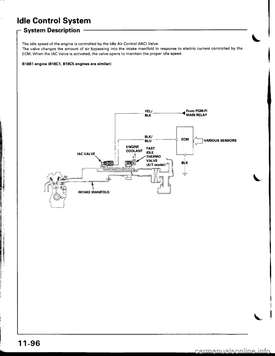
ldle Control System
System Description
The idle speed of the engine is controlled by the ldle Air Control (lAC) V8lve.
The valve changes the amount of air bypassing into the intake manifold in response to electric current controlled by the
ECM. When the IAC Valve is activated. the valve opens to maintain the proper idle speed.
81881 engine {B18Cl, B18C5 engines are similarl:
YELI - F.om PGM'FIBLK - MAIN RELAY
VARIOUS SENSORS
L
1 1-96
Page 302 of 1681
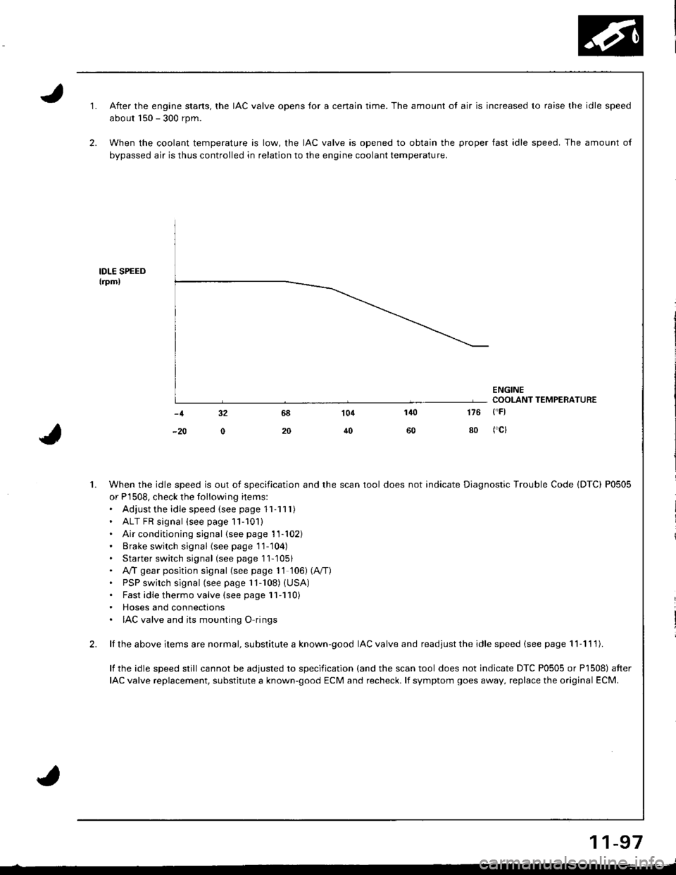
2.
1.
1.
2.
After the engine stans, the IAC valve opens for a certain time. The amount ol air is increased to raise the idle speed
about 150 - 300 rpm.
When the coolant temperature is low, the IAC valve is opened to obtain the proper fast idle speed. The amount of
bypassed air is thus controlled in relation to the engine coolant temperature.
IDLE SPEEDtrpm,
ENGINECOOLANT TEMPERATURE
140
50
104
40
-1 32
-20 0
176 ('F)
80 fcl
When the idle speed is out of specification and the scan tool does not indicate Diagnostic Trouble Code (DTC) P0505
or P'1508, check the following items:. Adiust the idle speed (see page '11-111)
' ALT FR signal (see page 11-101). Air conditioning signal {seepage'11-102)' Brake switch signal (seepagell-104)
. Starter switch signal (see page 11-1051. A,4 gear position signal (see page 1l 106) (A"/T)
. PSP switch signal (see page 11-108) (USA)
. Fast idle thermo valve (see page 11-110). Hoses and connections. IAC valve and its mounting O rings
ll the above items are normal, substitute a known-good IAC valve and readjust the idle speed (see page 'l I -1 1 l).
lf the idle speed still cannot be adjusted to specification (and the scan tool does not indicate DTC P0505 or P1508) after
IAC valve replacement, substitute a known-good ECM and recheck. lf symptom goes away, replace the original ECM.
11-97
Page 305 of 1681
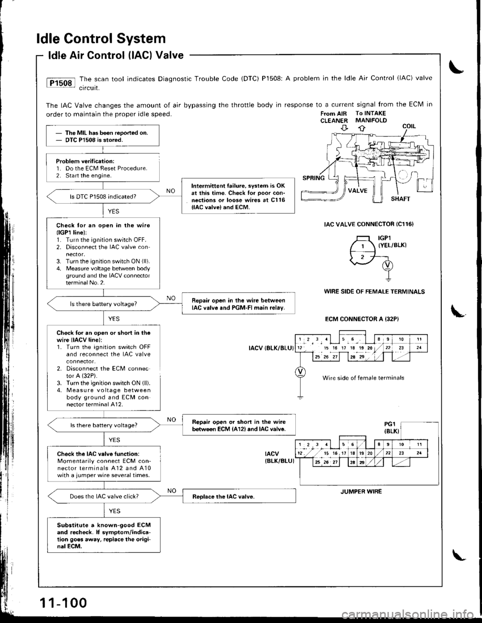
ldle Control System
Problem verification:'1. Do the ECM Feset Procedure.2. Sta rt the engine.
ldle Air Control (lAG) Valve
The scan tool indicates Diagnostic Trouble Code (DTC) P1508: A problem in the ldle Air Control (lAC) valve
crrcurt.
The IAC Valve changes the amount of air bypassing the throttle body in response to a current signal from the Eclvl in
order to maintain the proper idle speed.FTom AIB To INTAKECLEANER MANIFOLD
IAC VALVE CONNECTOR IC116}
YES
WIRE SIDE OF FEMALE TERMINALS
ECM CONNECTOR A {32PI
Check for an open or short in thewire IIACV line):1. Turn the agnition switch OFFand reconnect the IAC valve
2. Disconnect the ECM connector A (32P).
3. Turn the ignition swatch ON (ll).
4. M easu re voltage betweenbody ground and ECM connector terminal A12.
IACV {8LK/BLU}
tacv{BLK/BI-UI
The MIL has been reoorted on.OTC Pl508 is stored.
lntermittent failure, svstem is OKat this time. Check for ooor con-nections or loose wires at C116{lAC valvel and ECM.
ls DTC P1508 indicated?
Check tor an open in lhe wirellGPl line):1. Turn the ignition switch OFF.2. Disconnect the IAC valve con
3. Turn the ignition switch ON (ll).
4. Measure voltage betlveen bodyground and the IACV connectorterminalNo.2.
Repair open in the wire betweenIAC valve and PGM-FI main relav-ls there battery voltage?
Repair open or shon in the wi.ebetween ECM {A12l and lAc valve.ls there battery voltage?
Check the IAC velve function:Momentarily connect ECM con-nector terminals A12 and A10with a jumper wire several times.
Does the IAC valve click?
Substitute a known-good ECMand rocheck. lf symptom/indica-tion goes away. replace the origi-nal ECM.
','*',,'Llu.9', I l112 15 16 17 1a1o20/
l--12u1 z"-if1za-2"' . '1 .
910
t-r '21
Wire side of female terminals
JUMPER WIRE
1-100
Page 315 of 1681
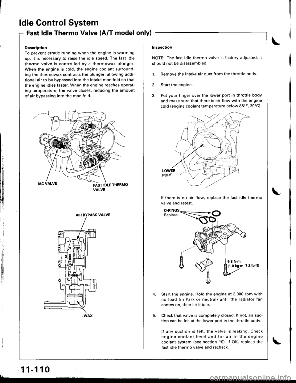
ldle Control System
Fast ldle Thermo Valve (A/T model onlylFast ldle I nermo valve (A/ | mooel
Description
To prevent erratic running when the engine is warming
up. it is necessary to raise the idle speed. The fast idle
thermo valve is controlled by a thermowax plunger.
When the engine is cold, the engine coolant surround-
ing the thermowax contracts the plunger, allowing addi
tional air to be bvoassed into the intake manifold so that
the engine idles taster. When the engine reaches operat-
ing temperature, the valve closes. reducing the amount
of air bypassing into the manifold.
FAST IDLE THERMO
VALVE
VALVE
wAx
Inspection
NOTE: The fast idle thermo valve is factory adiusted; it
should not be disassembled.
1. Remove the intake air duct from the throttle body.
2. Start the engine.
3. Put your finger over the lower port in throttle body
and make sure that there is air flow with the engine
cold {engine coolant temperature below 86'F, 30"c).
LOWERPORT
lf there is no air flow, replace the last idle thermo
valve and retest.
Start the engine. Hold the engine at 3,000 rpm with
no load (in Park or neutral) until the radiator fan
comes on, then let it idle.
Check that valve is completely closed. lf not, air suc-
tion can be felt at the lower port in the throttle body.
l{ any suction is felt, the valve is leaking. Check
engine coolant level and for air in the engine
coolant system (see section 10). It OK, replace the
fast idle thermo valve and recheck.
5.
{1.0 kg.m,7.2lbftl
l
11-110
lL.�
Page 322 of 1681
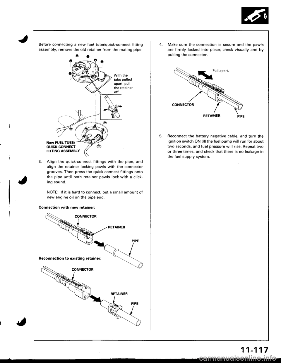
Before connecting a new fuel tube/quick-connect fitting
assembly, remove the old retainer from the mating pipe.
With rhetabs pulled
apart, Pullthe retaineroff
New FUEL TUBE/OUICK.CONNECTFTflNG ASSEMBLY
3. Align the quick-connect fittings with the pipe, and
align the retainer locking pawls with the connector
grooves. Then press the quick connect fittings onto
the pipe until both retainer pawls lock with a click-
Ing souno.
NOTE: lf it is hard to connect, put a small amount of
new engine oil on the pipe end.
Connection with new retainer:
5.
Make sure the connection is secure and the pawls
are lirmly locked into place; check visually and by
pulling the connector.
RETAINER
Reconnect the battery negative cable, and turn the
ignition switch ON (ll) the fuel pump wjll run for about
two seconds, and fuel pressure will rise. Repeat two
or three times, and check that there is no leakage in
the fuel supply system.
11-117
Page 328 of 1681
'*
1i
v3
I
l
i
I
1.
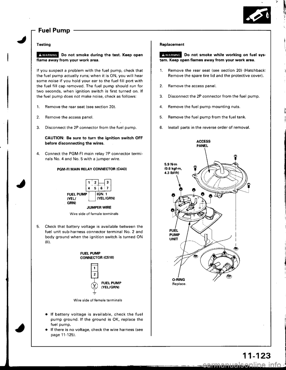
Testing
!@ Do not smoke during tho t€st. Keep open
flame away from your work area.
lf you suspect a problem with the fuel pump, check that
the fuel pump actually runs; when it is ON, you will hear
some noise it you hold your ear to the fuel fill pon with
the fuel fill cap removed. The fuel pump should run for
two seconds, when ignition switch is first turned on. lf
the fuel pump does not make noise, check as followsl
Remove the rear seat (see section 20).
Remove the access panel.
Disconnect the 2P connector from the tuel pump.
CAUTION: Be sure to turn the ignition switch OFF
before disconnecting the wires,
Connect the PGM-Fl main relay 7P connector termi-
nals No. 4 and No. 5 with a jumper wire.
PGM-FI MAIN RELAY CONNECTOR {C,14:}l
2.
3.
4.
5.
FUEL PUMP
{YEL/GRNI
IGN, 1
IYEL/GRN)
JUMPER WIRE
Wire side of female terminals
Check that battery voltage is available between the
fuel unit sub-harness connector terminal No. 2 and
body ground when the ignition switch is turned ON(
).
Wire side of female terminals
lf battery voltage is available, check the fuel
pump ground. lf the ground is OK. replace the
fuel pump.
lf there is no voltage, check the wire harness (see
page 11'125).
FUEL PUMPCoNNECTOR 1C510)
L]l
lrl-r
6l FUEL PUMP
\:/ (YEL/GRNI
4.
Replacemont
@ Do not smoke while working on tuel sys-
tem, Keep open flames away trom your work area.
'1. Remove the rear seat (see section 20) (Hatchbackl
Remove the spare tire lid and the protective cover),
2. Remove the access panel.
3. Disconnect the 2P connector trom the fuel oumD.
Remove the fuel pump mounting nuts.
Remove the fuel pump from the fueltank.
install parts in the reverse order of removal.
ACCESSPANEL
5.9 N.m(0.6 kgl.m,4.3 tbtft)
5.
Replace.