cable HONDA INTEGRA 1998 4.G Repair Manual
[x] Cancel search | Manufacturer: HONDA, Model Year: 1998, Model line: INTEGRA, Model: HONDA INTEGRA 1998 4.GPages: 1681, PDF Size: 54.22 MB
Page 988 of 1681
iii
i
I
J
Heater
fffustrated Index ............. ......'..21-2
Heater Door Positions '....'........ 21-3
Circuit Diagram ....................... 21-6
Troubleshooting
Symptom Chart ............. '.....21-8
Flowcharts
Blower Motor Speed ...............'......'........ 21 -9
Blower Motor ............'......21-11
Mode Controf Motor ............ ............'... "' 21 -14
Recirculation Control Motor ......'...... "'.,.,. 21 -1 7
Heater Control Panel Input/
Output Signals ...'.......... 21-19
Blower Unit
Replacement ........ '....... ',..,.. 21-2O
Overhaul ",',..21-21
*Heater Unit
Repf acement .....'.....'........'.. 21'22
Overhaul .......21-24
Heater Control Panel
Repfacement ....... '..... '......... 21-25
Overhaul .......21-26
Heater Valve Cable
Adjustment '.. 21'27
Air Mix Control Cable
Adiustment ... 21-27
Mode Control Motor
Test .............. ..................... 21'24
Repfacement ....................... 21-24
Recirculation Control Motor
Test .............. ..................... 21-29
Repf acement .........'........ " ". 21-29
Relay
Test .............. ..................... 21-3O
Heater Fan Switch
Test .............. ....................' 21-30
Mode Control Switch
Test .............' "'..............'... 21-31
Recirculation Control Switch
Test .............. ..................... 21-31
*: Read SRS precautions before working in this area.
Page 989 of 1681
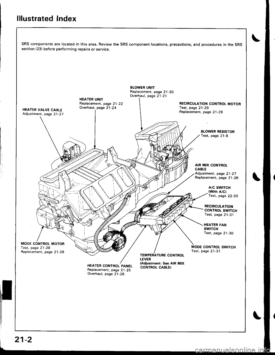
lllustrated Index
SRS components are located in this area. Review the SRS component locations. precautions, and procedures in the SRSsection (23) before performing repairs or service.
BLOWER UNITReplacement, page 21-2OOverhaul, page 21.21
HEATER VALVE CABLEAdiustment, page 21-27
HEATER UNITReplacement, page 21-22Overhaul, page 21-24RECIRCULATION CONTROL MOTORIest, page 21,29Seplacement, page 21-29
BLOWER RESISTORTest, page 21-9
AIR MIX CONTROLCABLEAdjustment, page 21-27Replacement, page 21-26
A/C SWTTCH{with A/clTest, page 22-20
RECIRCULATIONCONTROL SWITCHTest, page 21,31
HEATER FANswrTcHTest, page 21-30
MODE CONTROL MOTORTest, page 21-28Replacement, page 2 l -28CONTROL SWITCHTest, page 21-3'l
HEATER CONTROL PANELReplacement, page 21,25Overhaul, page 21-26
TEMPERATURE CONTROLLEVERlAdjustment: Soe AIR MIXCONTROL CABLEI
21-2
Page 995 of 1681
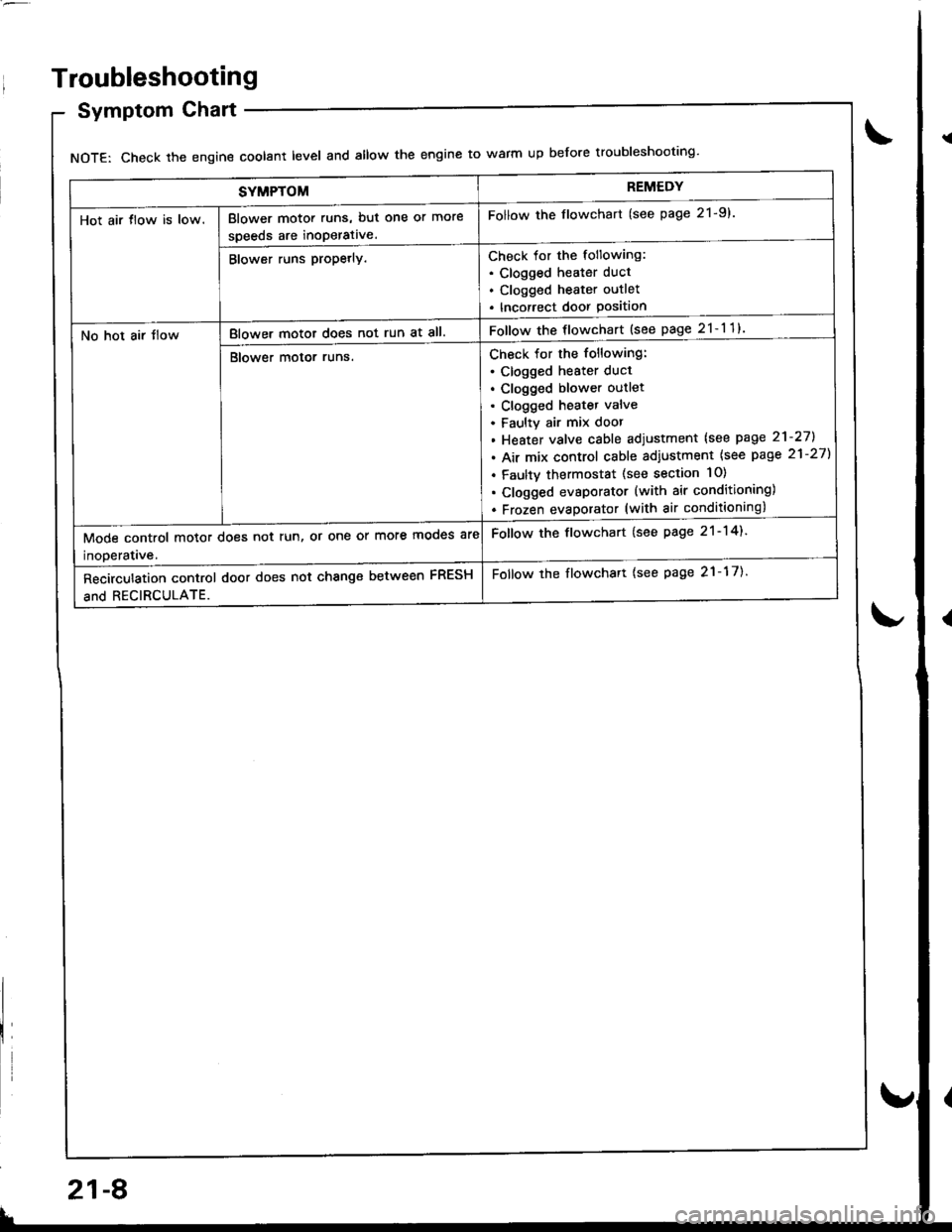
SYMPTOMREMEDY
Hot air tlow is low.Blower motor runs, but one or more
speeds are inoperative.
Follow the flowchart (see page 21-9).
Blower runs propetly.Check for the following:. Clogged heater duct
. Clogged heater outlet
. Incorrect door Position
No hot air tlowBlower motor does not run at all.Follow the flowchart {see page 21-11}
Blower motor runs.Check for the following:
. clogged heater duct
. Clogged blower outlet. Clogged heatet valve
. Faultv air mix door
. Heater valve cable adjustment lsee page 21-27].
. Air mix control cable adiustment {see page 21-27)
. Faulty thermostat (see section 10)
. Clogged evsporator (with air conditioning)
. Frozen evaDorator (with air conditioning)
Mode control motor does not run, or one or more mooes are
inoDeratave.
Follow the flowchart (see page 21-14).
Recirculation control door does not change between FRESH
and RECIRCULATE.
Follow the flowchart {see page 21-17).
Troubleshooting
Symptom Chart
NOTE: Check the engin€ coolant level and allow the engine to warm up before troubleshooting'
21-8
v
Page 1009 of 1681
Heater Unit
Replacement
SRS components are located in this area. Review the
SRS component locatio.s, precautions, and procedures
in the SRS section (23) before performing repairs or ser-
vtce.
1. When the engine is cool, drain the engine coolant
from the radiator (see section 1O).
@ oo not remove the radiator cap when
the engine is hot; the engine coolant is undol
prsssure and could sevdely scald you.
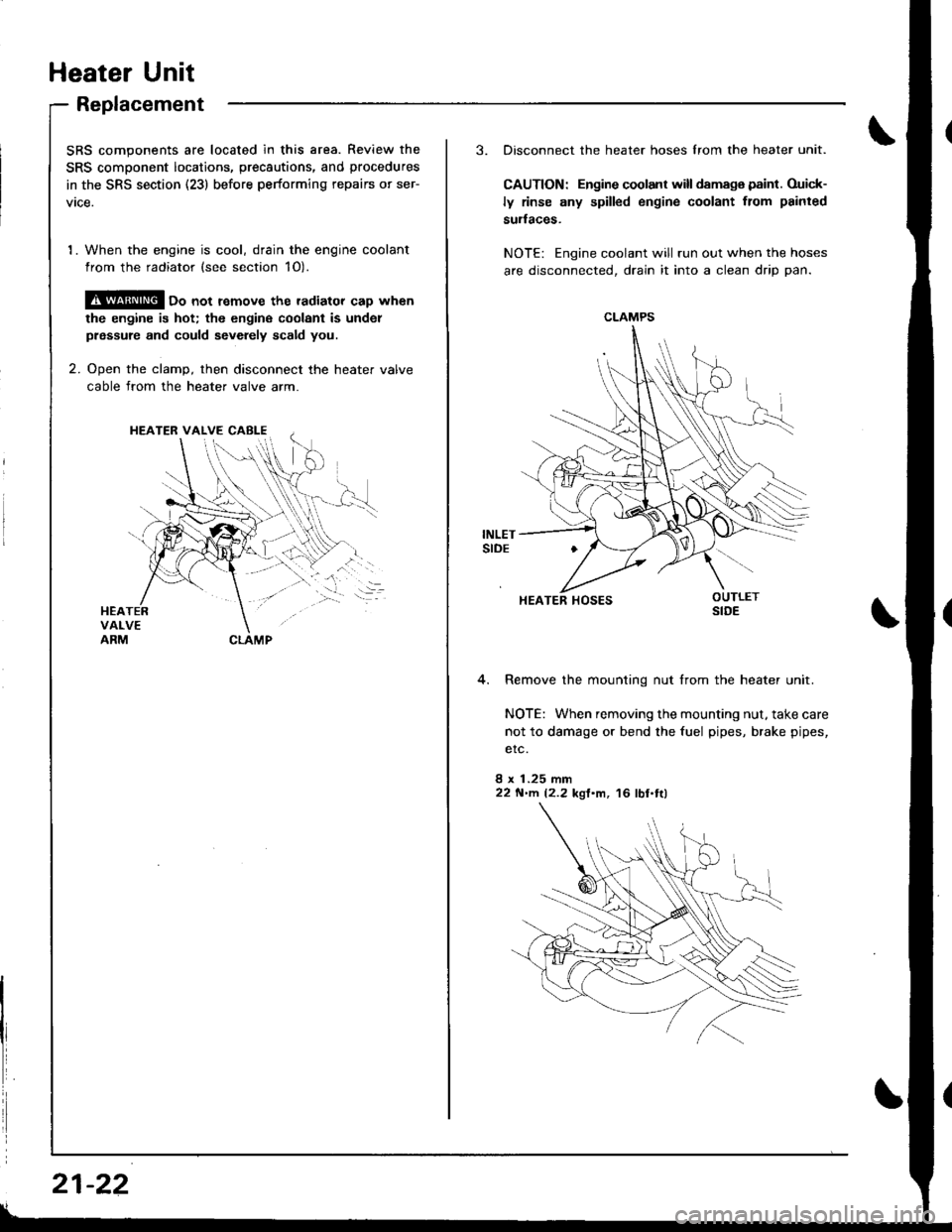
2. Ooen the clamD, then disconnect the heater valve
cable from the heater valve arm.
HEATER VALVE CABI-E
I
i
21-22
3. Disconnect the heater hoses lrom the heater unit.
CAUTION: Engine coolant will damaga paint. Ouick-
ly rinse any spilled engine coolant from painted
sudaces.
NOTE: Engine coolant will run out when the hoses
are disconnected, drain it into a clean drip pan.
4. Remove the mounting nut from the heater unit.
NOTE: When removing the mounting nut, take care
not to damage or bend the fuel pipes, brake pipes,
etc.
8 x 1.25 mm22 N'llt. 12.2 kgl'm, 16 lbl.tl)
CLAMPS
HEATER HOSES
Page 1010 of 1681
.J
5.
6.
7.
8.
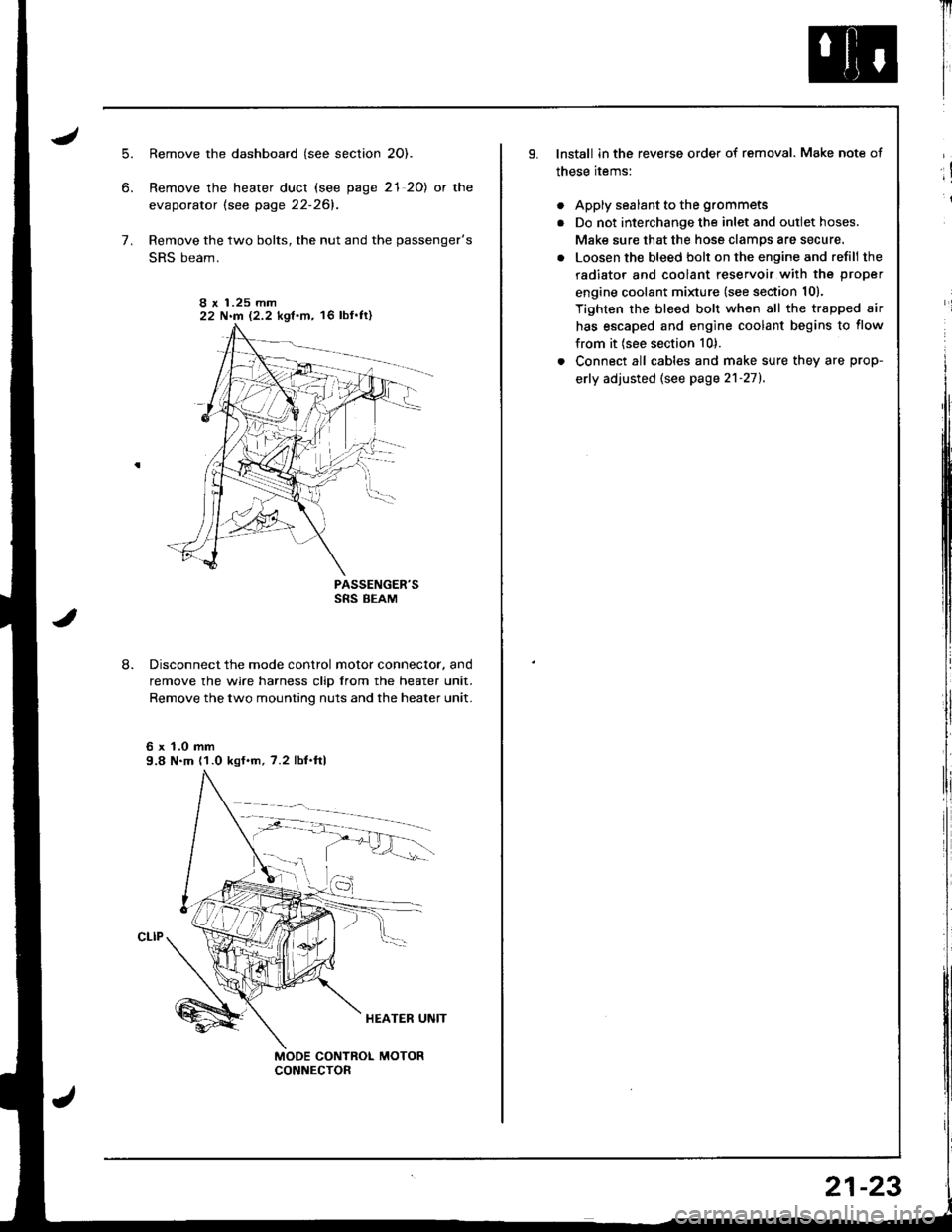
Remove the dashboard (see section 2O).
Remove the heater duct (see page 21 20) or the
evaporator lsee page 22-261.
Remove the two bolts, the nut and the passenger's
SRS beam.
PASSENGER'SSRS BEAM
Disconnect the mode control motor connector. and
remove the wire harness clip from the heater unit.
Remove the two mounting nuts and the heater unit.
6 x 1.0 mm9.8 N.m (1.0 kgf.m, 7.2 lbf.ftl
I r 1.25 mm22 N.m 12.2 kgf.m, 16 lbf'ft)
Il
I
I
lnstall in the reverse order of removal. Make note of
these items:
. Apply sealant to the grommets
. Do not interchange the inlet and outlet hoses.
Make sure that the hose clamps are secure.
. Loosen the bleed bolt on the engine and refill the
radiator and coolant reservoir with the proper
engine coolant minure (see section 10).
Tighten the bleed bolt when all the trapped air
has escaped and engine coolant begins to flow
from it (see section 10).
. Connect all cables and make sure they are prop-
erly adjusted (see page 2'l-271.
;!
i
21-23
Page 1012 of 1681
Heater Control Panel
Replacement
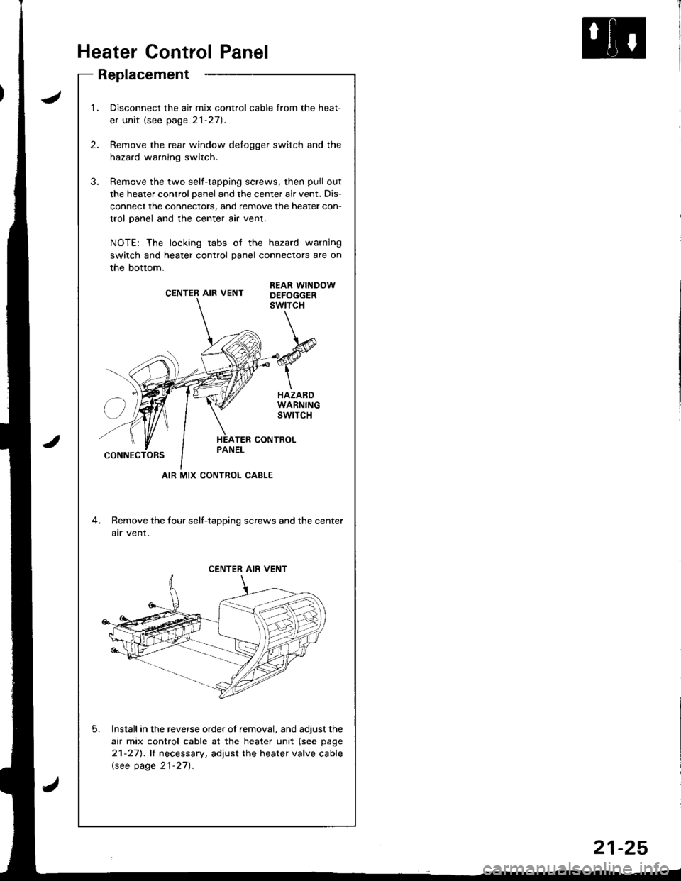
J
2.
1.Disconnect the air mix control cable from the heat
er unit (see page 21-27).
Remove the rear window delogger switch and the
hazard warning switch.
Remove the two self-tapping screws, then pull out
the heater control panel and the center air vent. Dis-
connect the connectors, and remove the heater con-
trol panel and the center air vent.
NOTE: The locking tabs of the hazard warning
switch and heater control panel connectors are on
the bottom.
CENTER AIR VENTREAR WINDOWD€FOGGERswtrcH
HAZARDWARNINGswrTcH
CONNECTORS
4. Remove the four self-tapping screws and the center
atr vent.
Install in the reverse order of removal, and adjust the
air mix control cable at the heater unit (see page
21-271.lt necessary, adjust the heater valve cable
lsee page 21-27).
5.
AIR MIX CONTROL CABLE
CENTER AIR VENT
21-25
Page 1013 of 1681
HEATER FAN SWITCHTest, page 21 30
AIR MIX CONTROL CABLEAdjustment, page 21-27
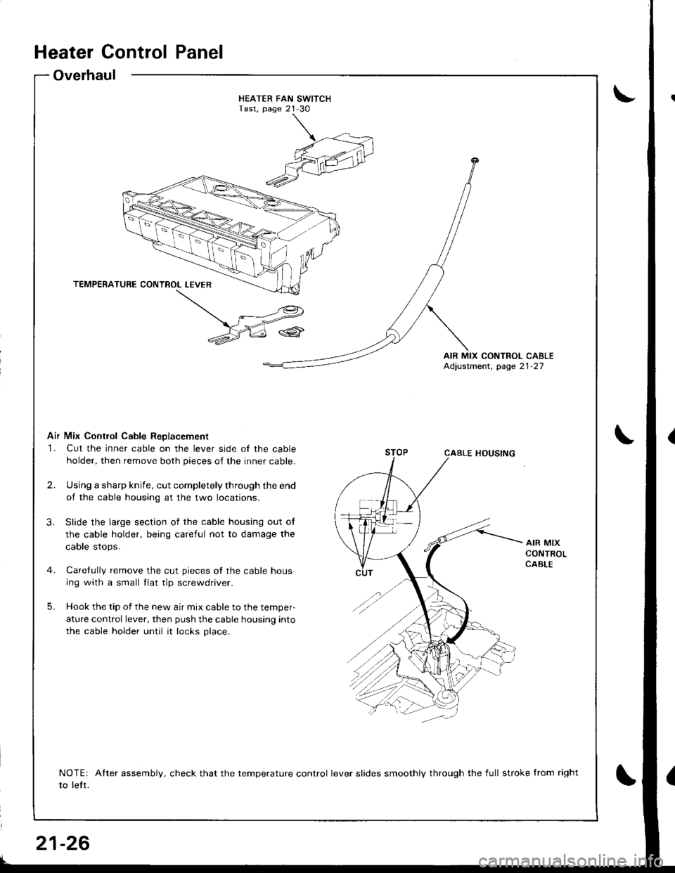
Air Mix Contlol Cable ReDlacement
1. Cut the inner cable on the lever side of the cable
holder, then remove both pieces of the inner cable.
2.Using a shafp knife, cut completely through the end
of the cable housing at the two locations.
Slide the large section of the cable housing out of
the cable holder, being careful not to damage the
cable stops.
Carefully remove the cut pieces of the cable hous
ing with a small tlat tip screwdriver.
Hook the tip of the new air mix cable to the temper-
ature control lever, then push the cable housing into
the cable holder until it locks place.
3.
AIR MIXCONTROLCABLE
5.
NOTEr Atter assembly, check that the temperature control lever slides smoothly through the full stroke from right
to left.
Heater Control Panel
Overhaul
t
21-26
Page 1014 of 1681
Heater Valve Cable
Adjustment
Air Mix Control Cable
Adjustment
lnri
I
I
I
I
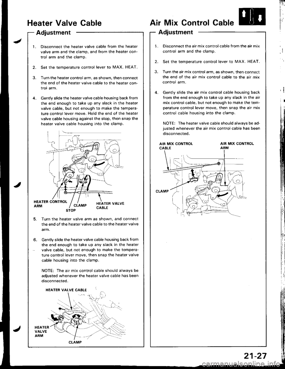
l.Disconnect the heater valve cable from the heater
valve arm and the clamp, and from the heater con-
trol arm and the clamp.
Set the temperature control lever to MAX. HEAT.
Turn the heater control arm, as shown, then connect
the end of the heater valve cable to the heater con-
trol arm.
Gently slide the heater valve cable housing back from
the end enough to take up any slack in the heater
valve cable, but not enough to make the tempera-
ture control lever move. Hold the end of the heater
valve cable housing against the stop, then snap the
heater valve cable housing into the clamp.
HEATER CONTROLARM
HEATERVALVEARM
HEATER VALVECABLECLAMP
5. Turn th€ heater valve arm as shown, and connect
the end of the heater valve cable to the heater valve
arm.
STOP
6. Gently slide the heater valve cable housing back from
the end enough to take up any slack in the heater
valve cable, but not enough to make the tempera-
ture control lever move. then snap the heater valve
cable housing into the clamp.
NOTE: The air mix control cable should alwavs be
adjusted whenever the heater valve cable has been
disconnected.
HEATER VALVE CABLE
,i$.
CLAMP
1.Disconnect the air mix control cable from the air mix
control arm and the clamp.
Set the temperature control lever to MAX. HEAT.
Turn the air mix controlarm, as shown, then connect
the end of the air mix control cable to the air mix
control arm.
Gently slide the air mix control cable housing back
from the end enough to take up any slack in the air
mix control cable, but not enough to make the tem-
perature control lever move, then snap the air mix
control cable housing into the clamp.
NOTE: The heater valve cable should always be ad-
justed whenever the air mix control cable has been
disconnected.
2.
3.
AIR MIX CONTROLCABLEAIR MIX CONTROLARM
21-27
Page 1039 of 1681
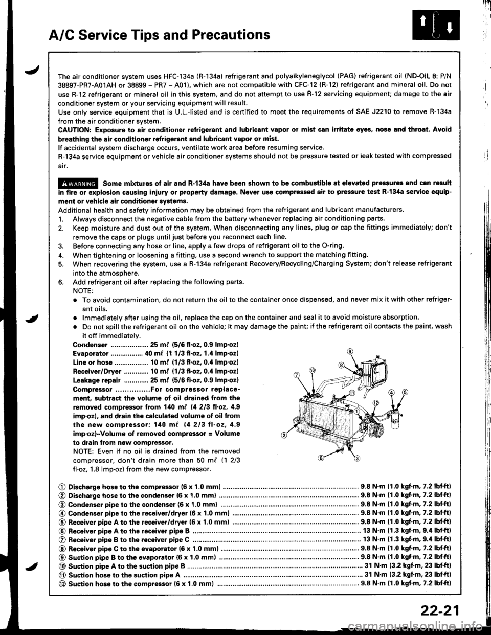
A/C Service Tips and Precautions
The air conditioner system uses HFC-134a (R-134a) refrigerant and polyalkyleneglycol {PAG) refrigerant oil (ND-OlL 8: P/N
38897-PR7-A01AH or 38899 - PR7 - A01), which are not compatible with CFC-12 (R-12) refrigerant and mineral oil. Do not
use R-12 refrigerant or mineral oil in this system. and do not attempt to use R-12 servicing equipment; damage to the air
conditioner system or your servicing equipment will result.
Use only service equipment that is U.L.-listed and is certified to meet the requirements of SAE J2210 to remove R-l34a
from the air conditioner system.
CAUTION: Exposure to air conditioner refrigerant and lubricant vapor ot mist can irritate eyos, nose.nd throat, Avoid
breathing th€ air conditionsr rofrigerant 8nd lubricant vapo. or mist.
lf accidental system discharge occurs, ventilate work area before resuming service.
R-134a service equipment or vehicle air conditioner systems should not be pressure tested or leak tested with comp.essed
atf,
@ some mixtures ol air and R-13i[a have been shown to be combustible at olevat6d pre3sures and cln resuh
in fire or explosion causing iniury or property damage. Nover uso compressed air to prossure te3t R-13,[8 service equip-
ment or vehicle air condition6r systems.
Additional health and safety information may be obtained from the refrigerant and lubricant manufacturers,
1. Always disconnect the negative cable from the battery whenever replacing air conditioning parts.
2. Keep moisture and dust out of the system. When disconnecting any lines. plug or cap the Jittings immediately; don't
remove the caps or plugs until just before you reconnect each line.
3. Before connecting any hose or line, apply a few drops of refrigerant oilto the O-ring,
4. When tightening or loosening a fitting, use a second wrench to support the matching fitting.
5. When recovering the system. use a R-134a refrigerant Recovery/Recycling/Charging System; don't release refrigerant
into the atmosphere.
6. Add refrigerant oil after replacing the following parts.
NOTE:
. To avoid contamination, do not return the oil tothe container once dispensed, and never mix itwith other refriger-
ant oils.
.lmmediatelyafterusingtheoil,replacethecaponthecontainerandseal it to avoid moisture absorption.
. Do notspillthe refrigerant oil onthevehicle; it maydamagethe painu itthe refrigerant oil contacts the paint, wash
it off immediately.
Coodansor ..-.-.-............. 25 mt (5/6 ll.oz. 0.9 lmp.oz)
Evaporator ................. ,[0 m/ (1 1/3 fl.oz, 1.4 lmp.ozl
Line or hoss .................. 10 m? {1/3fl.oz, 0.'l lmp.ozl
Receiver/Dryer ............. 10 m/ (1/3 fl.oz, 0.4 lmp.ozl
Leskage repair .............25 m/ {5/6 fl.oZ, 0.9 lmp.oz)
Compreigor .....,......,..Fo1 comprgssor replace-
ment, subtract the volum€ of oil drained from the
removed comprassor lrom l/t{l m[ (1 213 ll.oz, 1,9
imp'ozl, and drain the calculated volume ot oil from
the new compressor: 140 m/ 11 213 ll.oz, 1.9
imp.oz)-Volum€ oI removed comprsssor = Volum€
to drain trom n€w compressor.
NOTE: Even if no oil is drained from the removed
comDressor, don't drain more than 50 m{ {1 2/3
fl.oz. 1.8 lmp.oz) from the new compressor.
O Dischargo hoso to the compressol (6 x 1.0 mml............................... 9.8 N'm (1.0 kgf.m, 7.2 lbf'ftl
@ Di3charge hose to the condenser {6 x 1,0 mm)
@ Condonser pipe to the condenser (6 x '1.0 mml
9.8 N'm (1.0 kgl.m, 7.2 lbf.ftl
.. 9.8 N.m (1.0 kgf.m,7.2lbl.ltl
@ Condenser pipe to the rec€ivor/dryer (6 x 1.0 mml
O Receiver pipe A to th8 recoiver/dryer (6 x 1.0 mml
@ Receiyar pipe A to lhe receiver pipe B ,...........
O Receiver pipe B to th8 .ocoiver pipe C ............
@ R€ceiver pipe C to the evaporator 16 x 1.0 mm)
@ Suction pipe B to th€ evaporator {6 x 1.0 mm) .......,.
@ Suqtion pipe A to the suction pipe B
O Suction hose to the suction pipe A ...........,.
@ Suction hose to the compressor 16 x 1.0 mml
9.8 N.m (1.0 kgf.m, 7.2 lbf.ftl
9.8 N'm (1.0 kgf.m, 7.2 lbf.fr)
13 N.m (1.3 kgf.m. 9.4 lbf.ft)
13 N.m (1.3 kgf.m,9.'l lbf.ftl
9.8 N.m (1.0 kgt m. 7.2 lbf.ftl
...... 9.8 N.m {1.0 kqf'm, 7.2 lbf.ft)
........ 31 N'm (3.2 kgf.m, 23 lbf.ft)
............ 31 N.m (3.2 kgf.m,23 lbtft)
..................... 9.8 N.m {r.0 kgf.m, 7.2 lbtft)
22-21
Page 1060 of 1681
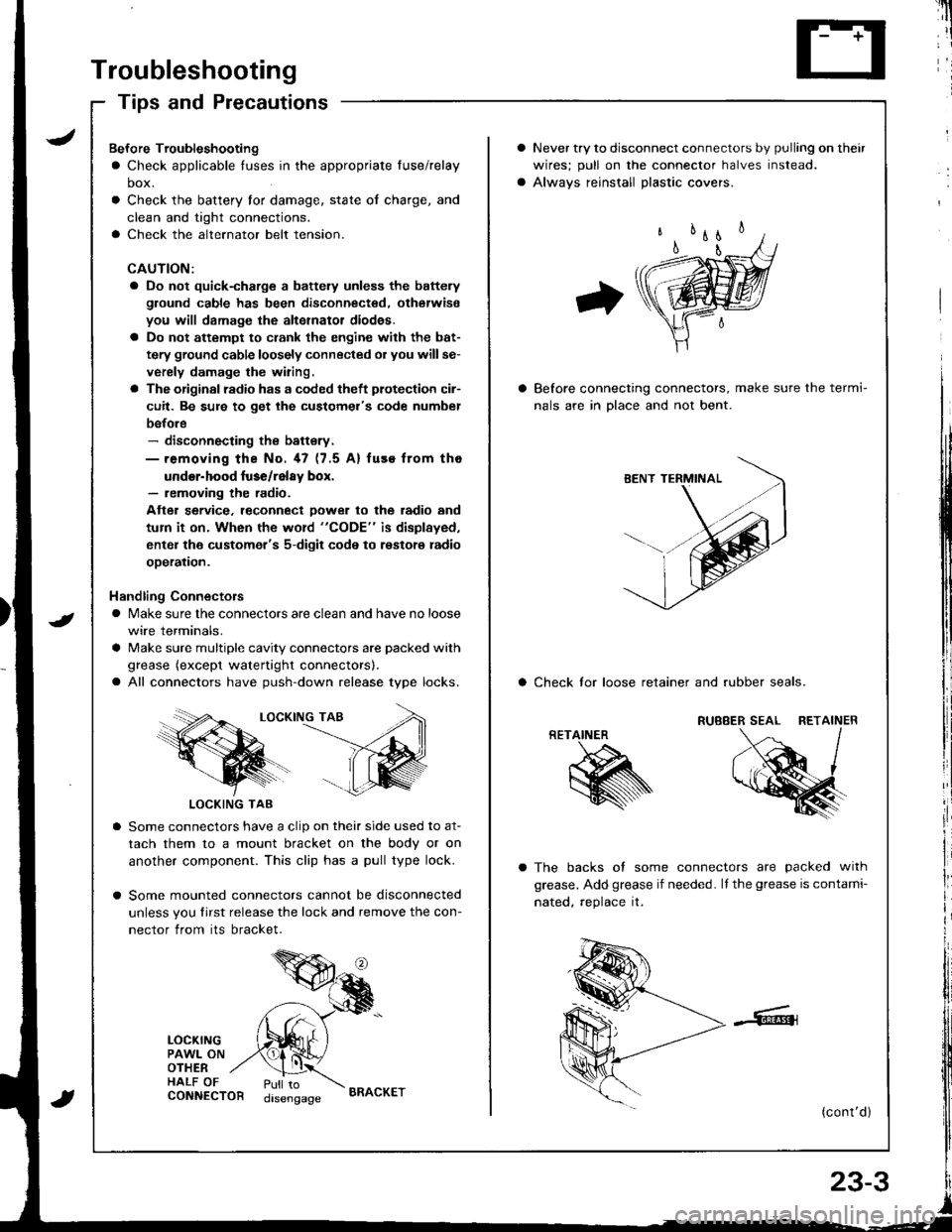
Troubleshooting
Tips and Precautions
Never try to disconnect connectors by pulling on their
wires; pull on lhe connector halves instead.
Alwavs reinstall Dlastic covers.
Before connecting connectors, make sure the termi-
nals are in Dlace and not bent.
a Check lor loose retainer and rubber seals.
The backs of some connectors are packed with
grease. Add grease if needed. lf the grease is contami-
nated, reolace it.
(cont'd )
RETAINER
K
Bef ore Troubleshooting
a Check applicable tuses in the appropriate fuse/relay
box.
Check the battery for damage, state of charge, and
clean and tight connections.
Check the alternator belt tension.
CAUTION:
a Do not quick-charge a battely unless the battery
ground cable has been disconnected. otherwise
you will damage the alternator diod€s.
a Do not attempt to crank the engine with the bat-
tery ground cable loosely connected or you willse-
verely damage the wiring.
a The originsl radio has a coded theft plotection cir-
cuit. Be sure to get the customel's code numbel
before- disconnecting the battsry.- removing the No. 47 (7.5 A) fuse from tho
under-hood luse/relay box.- removing the radio.
Atter service. leconnect Dower to the radio and
tum it on. When the word "CODE" is displayed,
enter the customer's 5-digit code to restore radio
ooeration.
Handling Connectors
a Make sure the connectors are clean and have no loose
wire terminals.
a Make sure multiple cavity connectors are packed with
grease (except watertight connectors).
a All connectors have push-down release type locks.
LOCKING TAB
LOCKING TAB
Some connectors have a clip on their side used to at-
tach them to a mount bracket on the body or on
another component. This clip has a pull type lock.
Some mounted connectors cannot be disconnected
unless you tirst release the lock and remove the con-
nector from its bracket.
LOCKINGPAWL ONOTHERHALF OFCONNECTORPull todisengageBRACKET