check oil HONDA INTEGRA 1998 4.G Owner's Manual
[x] Cancel search | Manufacturer: HONDA, Model Year: 1998, Model line: INTEGRA, Model: HONDA INTEGRA 1998 4.GPages: 1681, PDF Size: 54.22 MB
Page 184 of 1681
3.
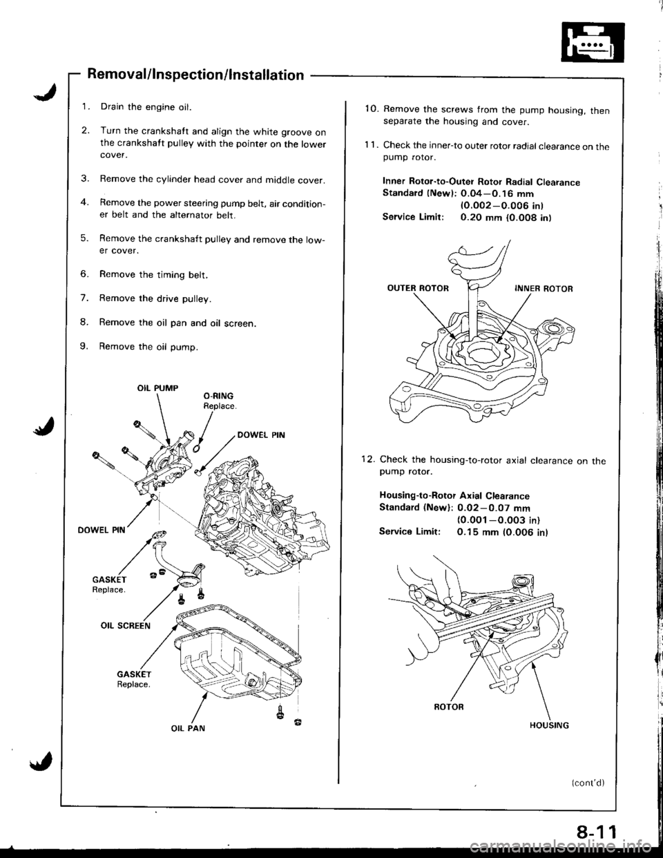
Removal/lnspection/lnstallation
Drain the engine oil.
Turn the crankshatt and align the white groove onthe crankshatt pulley with the pointer on the lowercover.
Remove the cylinder head cover and middle cover.
Remove the power steering pump belt, air condition-er belt and the alternator belt.
Remove the crankshaft pulley and remove the low-er cover.
6. Remove the timing belt,
7. Remove the drive pulley.
8. Remove the oil pan and oil screen.
9. Remove the oil pump.
OIL PUMP
OIL PAN
8-1
'10. Remove the screws from the pump housing, thenseparate the housing and cover.
1 1 . Check the inner-to outer rotor radial clearance on thepumD rotor.
Inner Rotor-to-Outei Rotor Radial ClearanceStandard (Newl: O.04-O.16 mm
lO.OO2-O.O06 int
Service Limir: 0.20 mm {0.O08 in)
12. Check the housing-to-rotor axial clearancepump rotor.
Housing-to-Rotor Axial Clearance
Standard (New): 0.02-0.07 mm(0.0O1 -O.003 in)
Service Limit: O.15 mm (0.006 inl
on tne
1
Page 185 of 1681
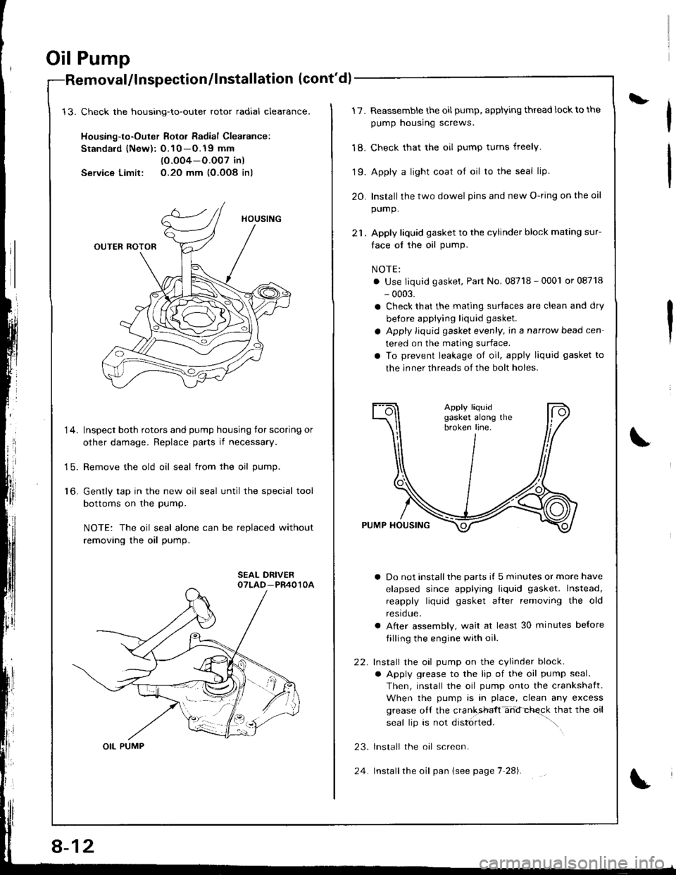
Oil Pump
Check the housing-to-outer rotor radial cleatance.
Housing-to-Outer Rotor Radial Clearance:
Standald (New): O.10 -O.19 mm
{0.O04-O.O07 in)
Service Limit: 0.2O mm (O.OO8 inl
Inspect both rotors and pump housing tor scoring or
other damage. Replace parts if necessary.
Remove the old oil seal from the oil pump.
Gently tap in the new oil seal until the special tool
bottoms on the pump.
NOTE: The oil seal alone can be replaced without
removing the oil pump.
alllnspection/lnstallation (cont'd)
14.
15.
to.
OIL PUMP
8-12
24
L17.
'18.
19.
20.
Reassemble the oil pump, applying thread lock to the
pump housing screws.
Check that the oil pump turns freely.
Apply a light coat of oil to the seal lip.
Install the two dowel pins and new O-ring on the oil
pump.
Apply liquid gasket to the cylinder block mating sur-
face ol the oil pump.
NOTE:
. Use liquid gasket, Part No, 08718 - 0001 or 08718
- 0003.
a Check that the mating surlaces are clean and dry
betore applying liquid gasket.
a Apply liquid gasket evenly, in a narrow bead cen
tered on the mating surface.
a To prevent leakage of oil, apply liquid gasket to
the inner threads of the bolt holes.
a Do not installthe parts il 5 minutes or more have
elapsed since applying liquid gasket. Instead,
reapply liquid gasket atter removing the old
resrdue.
a After assembly, wait at least 30 minutes before
filling the engine with oil.
Install the oil pump on the cylinder block.
a Apply grease to the lip of the oil pump seal.
Then, install the oil pump onto the crankshaft.
When the pump is in place, clean any excess
grease oll the cranksfft-hd-chqck that the oil
seal lip is not disl6rted. ".\
lnstall the oal screen.
Installthe oil pan (see page 7 28).
22.
23.
Page 202 of 1681
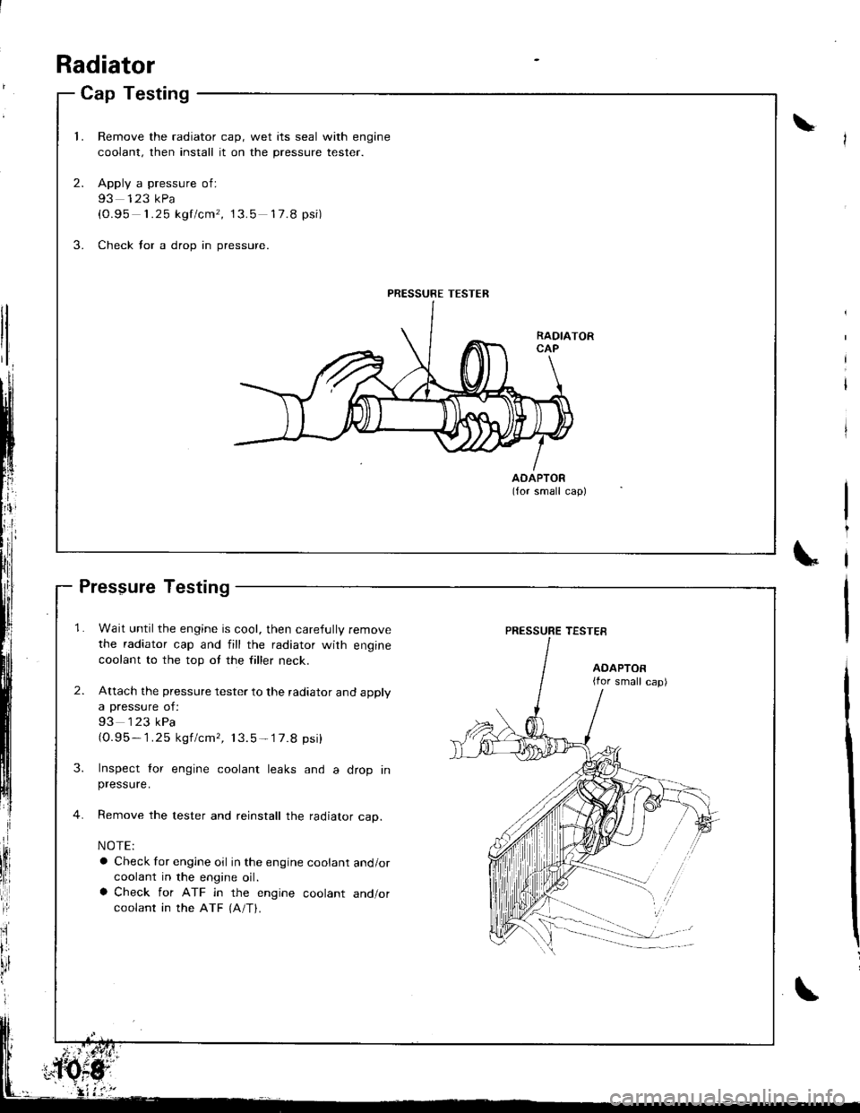
Cap Testing
1.Remove the radiator cap, wet its seal with engine
coolant, then install it on the pressure tester.
Apply a pressure of:
93 123 kPa(0.95 1.25 kgf/cm', 13.5 17.8 psi)
Check for a drop in pressure.
2.
3.
AOAPTOR(for small cap)
PRESSURE TESTER
Radiator
Pressure Testing
1. Wait until the engine is cool, then carefully remove
the radiator cap and fill the radiator with engine
coolant to the top ot the filler neck.
2. Attach the pressure tester to the radiator and apply
a pressure of:
93 123 kPa(O.95- 1.25 kgf/cmr, 13.5-'17.8 psi)
3. Inspect lor engine coolant leaks and a drop inpressure.
4. Remove the tester and reinstall the radiator cap.
NOTE:
a Check for engine oil in the engine coolant and/orcoolant in the engine oil.a Check for ATF in the engine coolant and/orcoolant in the ATF {A/T}.
\
PRESSURE TESTES
AOAPTOR{for small cap)
Page 245 of 1681
I
t
h,,l,!
il
Troubleshooting
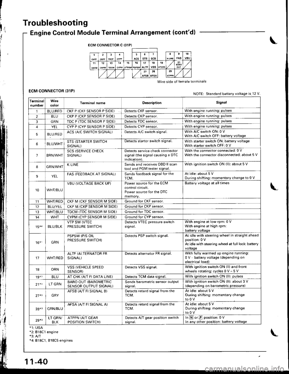
ECM CONNECTOR {31P)
Engine Control Module Terminal Arrangement (cont'd)
ECM CONNECTOR C {31P)
235srsscs1112t31515t71A19
2A
Wire side of lemale terminals
NOTE: Standard battery voltage is 12 V.
TerminalnumbercolorTerminal namoD6scriptionSignal
1BLU/REDCKF P (CKF SENSOR P SIDE)Detects CKF sensor.With engine running: pulses
28LUCKP P (CKP SENSOR P SIDE)Detects CKP sensor.With engine running: pulses
3GRNTDC P {TDC SENSOR P SIDE)Detects TDC sensor,With engine running: pulses
YELCYP P (CYP SENSOR P SIDE)Detects CYP sensor,With engine running: pulses
5BLU/REDACS (AJC SWITCH SIGNAL)Detects A,/C switch signal.With A,/C switch ON: 0 VWith A,/C switch OFF: battery voltage
6BLUA/VHTSTS (STARTEB SWITCHSIGNAL)
Detects starter switch signal.With staner switch ON: battery voltageWith starter switch OFF: 0 V
7BRN,AiVHTSCS (SERVICE CHECKSIGNAL)Detects service check connectorsignal (the signalcausing a DTC;ndication).
With the co n nector con nected: 0 VWath the connector disconnected: about 5 V
8GRNAVHTK LINESends and receives OBD ll scantool and PGM tester signal.With ignition switch ON (ll): about 5 V
9YELFAS lFEEDBACK AT SIGNAL)Sends feedback signal for theTCM,At idle: about 5 VDuring shifting: momenlary change to 0 V
10WHT/BLU
VBU (VOLTAGE BACK UP)Power source for the ECMcontrolcircuit,Power source for the DTC
Battery voltage at all times
t1WHT/REDCKF M (CKF SENSOR I\4 SIDE)Ground for CKF sensor.
12BLUI/E LCKP M (CKP SENSOR M SIDE)Ground for CKP sensor.
WHT/BLUTDCM (TDC SENSOR M SIDE)Ground tor TDC sensor.
14CYPM (CYP SENSOR M SIDE)Ground for CYP sensor.
15*.BLU/BLKVTP SW (VTEC
PRESSUFE SWITCH)Detects VTEC pressure switchsr9nal.
With engine at low rpm:0 VWith engine at high rpmlbattery voltaqe
161,GRN
PSPSW (P/S OILPRESSURE SWITCH)Derecls PSP switch signal.At idle with steering wheel in straight aheadpositioni 0 VAt idle with steering wheelat full lock: batteryvoltage
17WHT/REDALTF (ALTERNATOR FRSIGNAL)Detects alternator FR signal.With fully warmed up engine running:0 V battery voltage (depending onelectrical load)
18ORNVSS (VEHICLE SPEEDSENSORiDetects VSS signal.With ignition switch ON (ll) and lrontwheels rotating: cycles 0 V- 5 V
19*3BLUAT CHK (A/T FI DATA LINE)Detects TCM data signal.With ignition switch ON (ll)i pulses
21*LT GRNBARO OUT (SAROMETRIC
SENSOR OUTPUT S!GNAL)Sends barometric sensor outputsrgnal,With ignition switch ON (ll): about 3 V(depending on barometric pressure)
27 x3GRYAFSB (A"/T FI SIGNAL B)Detects retard signal from theTCM,At idle: about 5 VDuring shifting: momentary changeto0V
28+1GRN/8LUA+SA (A/T FI SIGNAL A)Detects retard signal from theTCM.At idle: about 5 VDuring shifting: momentarV changeto0V
29+3LT GRN/BLKATPPN (A/T GEARPOSITION SWITCH)Detects A,/T gear position switchsrgnal-In E orE positionr 0VIn anv other position: battery voltage
*1: USA*2:818C1 engine*3: A/T*4: 818C1, 818C5 engines
Page 255 of 1681
I
I
It:
PGM-FI System
Engine Control Module {ECMI
,i
I
{
ili
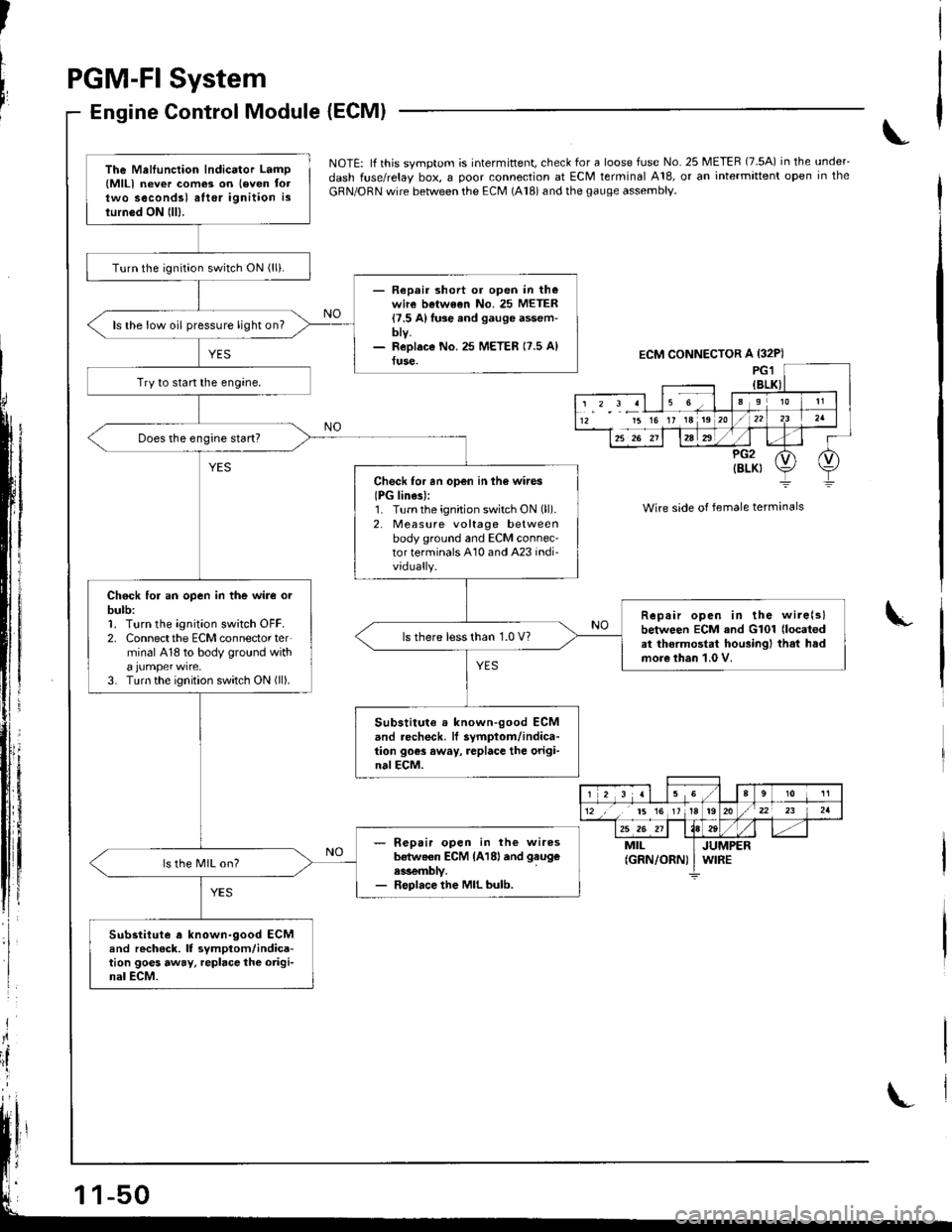
NOTE: lf this svmotom is intermittent, check for a loose fuse No. 25 METER (7.5A) in the under_
dash fuse/relay box, a ooor connection at ECM terminal A18, or an intermittent open in the
GRN/ORN wire between the ECM (A18) and the gauge assembly.
Wire side of female terminals
I
The Mellunction Indicator Lamp(MlLl never com€3 on leven foltwo secondsl alter ignition islurn6d ON lll).
Turn the ignition switch ON (lli.
- Repair short or open in th€wire betwe€n No. 25 METER{7.5 A}fuse and gauge assem-bty.- ReDlaco No.25 METER 17.5 A)fuse.
ls the low oil pressure light on?
Try to start the engine,
Check for an open in ih6 wires
IPG lines):1. Turnthe ignition switch ON (ll).
2. Measure voltage betweenbody ground and ECM connec-tor terminals A10 and A23 indi-vidually.
Chock for an open in the wire orbulb:1. Turn the ignition sw;tch OFF.2. Connectthe ECM connector terminal 418 to body ground with
3. Turn the ignition switch ON (ll).
Repair open in the wire(slbetween ECM and G101 (located
at thermostat housingl that hadmore than 1.0 V.
ls there less than 1.0 V?
Substitute . known-good ECMand .echeck, lf symptom/indica-tion goes away, replace the origi-nalECM.
- R€pair open in the wiresb€tweon ECM {A18land gaug€
ess€mbly.- Replace the MIL bulb.
ls the MIL on?
Substitute a known-9ood ECMand rech6ck. It symptom/indica-tion goes away, repbce the origi-nal ECM.
ECM CONNECTOR A {32P)
15 16 17 18 19
r 2 3 al 15 Ga910 11
12 ,, t5 16 1tt920/22 23 2a
25 26 211184tt-MILJUMPER(GRN/ORN) I WIRE
Page 322 of 1681
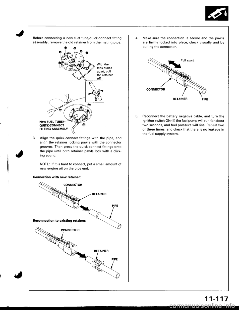
Before connecting a new fuel tube/quick-connect fitting
assembly, remove the old retainer from the mating pipe.
With rhetabs pulled
apart, Pullthe retaineroff
New FUEL TUBE/OUICK.CONNECTFTflNG ASSEMBLY
3. Align the quick-connect fittings with the pipe, and
align the retainer locking pawls with the connector
grooves. Then press the quick connect fittings onto
the pipe until both retainer pawls lock with a click-
Ing souno.
NOTE: lf it is hard to connect, put a small amount of
new engine oil on the pipe end.
Connection with new retainer:
5.
Make sure the connection is secure and the pawls
are lirmly locked into place; check visually and by
pulling the connector.
RETAINER
Reconnect the battery negative cable, and turn the
ignition switch ON (ll) the fuel pump wjll run for about
two seconds, and fuel pressure will rise. Repeat two
or three times, and check that there is no leakage in
the fuel supply system.
11-117
Page 325 of 1681
I
Fuel Supply System
Fuel Injector (cont'dlFuel Pressure Regulator
Description
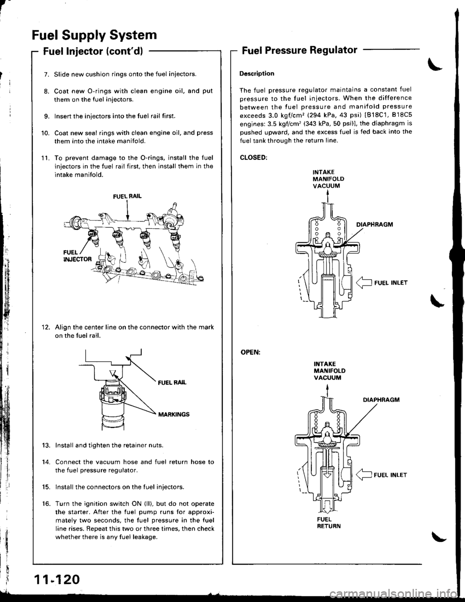
The fuel pressure regulator maintains a constant fuel
pressure to the fuel injectors. When the difference
between the fuel pressure and manifold pressure
exceeds 3.0 kgf/cm'� (294 kPa,43 psi) IB18C'1,818c5
engines:3.5 kglcm'(343 kPa,50 psi)l, the diaphragm is
Dushed uDward, and the excess fuel is fed back into the
fuel tank through the return line.
CLOSED:
INTAKEMANIFOLDVACUUM
I1{TAKEMANIFOLDVACUUM
DIAPHRAGM
< IFUEL INLET\-
\
OIAPHRAGM
/4_\T-J FUEL INLET
9.
10.
11.
7.
8.
1t
Slide new cushion rings onto the fuel iniectors.
Coat new O-rings with clean engine oil, and put
them on the fuel injectors.
Insert the injectors into the fuel rail first.
Coat new seal rings with clean engine oil, and press
them into rhe intake manifold.
To prevent damage to the O-rings, install the luel
injectors in the fuel rail first, then install them in the
intake manifold.
Align the center line on the connector with the mark
on the fuel rail,
FUEL RAIL
MARKINGS
13.
14.
15.
16.
Install and tighten the retainer nuts.
Connect the vacuum hose and fuel return hose to
the fuel pressure regulator.
lnstall the connectors on the fuel injectors.
Turn the ignition switch ON (ll). but do not operate
the starter. After the fuel pump runs for approxi'
mately two seconds, the fuel pressure in the fuel
line rises. Repeat this two or three times, then check
whether there is any fuel leakage.
FUEL RAIL
FUEL
Page 326 of 1681
Testing
@G Do not smoke during the test. Keep opon
flames away lrom your work ar€a.
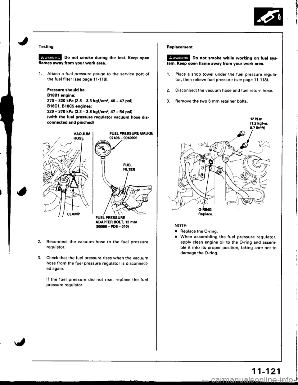
1. Attach a fuel pressure gauge to the service port of
the tuel filter (see page 11-118).
Pr€ssurs should be:
8188l €ngine:
27O - 320 kPa 12.8 - 3.3 kgl/cmr. 40 - 47 psil
818C1, 818C5 engines:
320 - 370 kPa (3.3 - 3.8 kgrf/cm,, 47 - 54 psi)
{with tho fuol pfossure regulatot vacuum hose dis-
connected and pinchsd)
FUEL PRESSURE GAUGE074t 6 - 004{1001
ADAPTER BOIT, 12 mm(9txt08-PD6-0101
Reconnect the vacuum hose to the fuel pressure
regulator.
Check that the fuel pressure rises when the vacuum
hose from the fuel pressure regulator is disconnect-
ed again.
lf the fuel pressure did not rise, replace the fuelpressure regulator.
VACUUM
FUEL PRESSURER€place.
AA
,il
I
I
Replacem6nl
@ Do not smoke while working on tucl sys-
tem. Keep open flamc away from your work area.
1. Place a shop towel under the fuel pressure regula-
tor, then relieve fuel pressure (see page 11-1'18).
2. Disconnect the vacuum hose and fuel return hose.
3. Remove the.two 6 mm retainer bolts.
NOTE:
. Replace the O-ring.
o When assembling the fuel pressure regulator,
apply clean engine oil to the O-ring and assem-
ble it into its proper position, taking care not to
damage the O-ring.
r1
i
i
11-121
Page 372 of 1681
aintenance
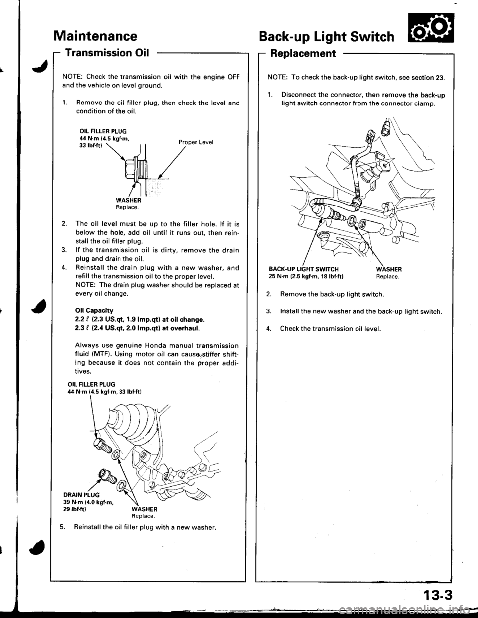
Transmission Oil
NOTE: Check the transmission oil with the engine OFF
and the vehicle on level ground.
1. Remove the oil filler plug, then check the level and
condition of the oil.
OIL FILLER PLUG44 N.m {4.5 kgf.m,Proper Level33 tbf.ftl
The oil level must be up to the filler hole. lf it is
below the hole, add oil until it runs out, then rein-
stall the oil filler plug.
lf the transmission oil is dirty, remove the drainplug and drain the oil.
Reinstall the drain plug with a new washer, and
refillthe transmission oilto the proper tevet.
NOTE: The drain plug washer should be replaced at
every oil change.
Oil Capacity
2.2 | i.2.3 US.qr,1.9 lmp.qtl at oil ch.nge.
2.3 t l2.1US.qt,2.O lmp.qtl at ovorhaul.
Always use genuine Honda manual transmission
fluid (MTF). Using motor oil can causa€tiffer shift-
ing because it does not contain the proper addi-
Back-up Light Switch
Replacement
NOTE: To check the back-up light switch. see section 23.
1. Disconnect the connector, then remove the back-up
light switch connector from the connector clamp.
l.m {2.5 kgf.m, 18lbf.ft) Replace.
Remove the back-up light switch.
Install the new washer and the back-up light switch.
Check the transmission oil level.
!ves.
OIL FILLER PLUG
DRAIN PLUG39 N.m {4.0 kg{.m,29 rbf.ftlReplace.
5. Reinstall the oil filler plug with a new washer,
Replace.
EACK.UP LIGHT SWITCH25 N.m {2.5 kgf.m, 18 lbf.ft)
13.3
Page 405 of 1681
I
\
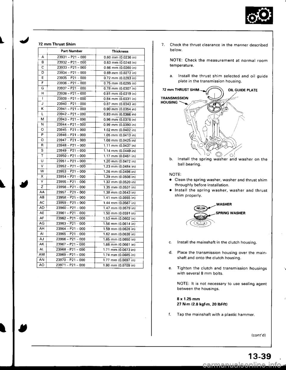
72 mm Thrust Shim
Part NumberThickness
23931 - P21 -0000.60 mm (0.0236 in)
B23932-P21-0000.63 mm (0.0248 in)
c23933 - P21 -0000.66 mm (0.0260 in)
D23934 P21 0000.69 mm (0.0272 in)
E23935 P21 - 0000.72 mm (0.0283In)
23936 P21 0000.75 mm (0.0295n)
G23937 - P21 0000.78 mm 10.0307n)
23938 - P21 -0000.81 mm 10.0319n)
23939 P21 - 0000.84 mm {0.0331n)
J23940 P21 0000.87 mm (0.0343 in)
K23941 - P21 -0000.90 mm (0.0354 in)
L23942 - P21 - 0000.93 mm (0.0366 in)
M23943 - P21 -0000.96 mm (0.0378 in)N23944-P21 -0000.99 mm {0.0390 in)
o23945 - P21 -0001.02 mm (0.0402 in)
23946 P2r - 0001.05 mm (0.0413 in)
o23947 P2r - 0001.08 mm (0.0425 in)
23948 P21 - 0001.11 mm (0.0437;ni
23949 P21 - 0001.14 mm (0.0449 ini
T23950-P21 -0001.17 mm (0.0461 in)
23951 - P21 -0001.20 mm (0.0472 in)
23952 P21 - O001.23 mm (0.0484 in)
23953 P21 - 0001.26 mm (0.0496 'n)
23954 - P21 000'1.29 mm (0.0508 in)
23955, P21 0001.32 mm (0.0520 in)
z23956 P21 - 0001.35 mm (0.0531 in)
23957 P2r - 0001.38 mm (0.0543 in)
AB23958 P21 - 0001.41 mm (0.0555 in)
AC23959-P21 -0001.44 mm (0.0567 in)
AD23960 P2r 0001.47 mm (0.0579 in)
AE23961 - P21 000L50 mm 10.0591 rn,
23962 - P21 0001.53 mm {0.0602 in)
AG23963, P21 0001.56 mm (0.0614 in)
AH23964 P21 0001.59 mm (0.0626 jn)
23965 P21 0001.62 mm (0.0638 in)
23966 - P21 0001.65 mm (0.0650 in)
AK23967-P2t-0001.68 mm (0.0661 In)
23968-P21 -0001.71 mm (0.0673 in)
23969 P21 - 0001.74 mm (0.0685 in)
AN23970 P21 - 0001.77 mm {0.0697 in)
AO23971 P21 - 000'l -80 mm {0.0709 in)
1.
72 mm THRUST
TRANSMISSIONHoustNG --'-.rft=>t
o
Check the thrust clearance in the manner described
oerow.
NOTE: Check the measurement at normal room
temperature.
a. Install the thrust shim selected and oil guide
plate in the transmission housing.
OIL GUIOE PLATE
b.
f.
NOTE:
. Clean the spring washer, washer and thrust shim
throughly before installation,
. Install the spring washer, washer and thrust
shim properly.
- -- /wAsHER(€>P-
X -spnrruc wlssen
a a.7l=\-\-
Install the mainshaft in the clutch housing.
Place the transmission housing over the main-
shaft and onto the clutch housing.
Tighten the clutch and transmission housings
with several I mm bolts.
NOTE: lt is not necessary to use sealing agent
between the housings.
8 x 1.25 mm
27 N.m (2.8 kgf.m, 20 lbt.ft)
Tap the mainshaft with a plastic hammer.
c.
o.
t:oInstall the spring
ball bearing.
wash erand washer on the
(cont'd)
il
13-39