check oil HONDA INTEGRA 1998 4.G Repair Manual
[x] Cancel search | Manufacturer: HONDA, Model Year: 1998, Model line: INTEGRA, Model: HONDA INTEGRA 1998 4.GPages: 1681, PDF Size: 54.22 MB
Page 701 of 1681
Power Steering Gearbox
Reassembly (cont'dl
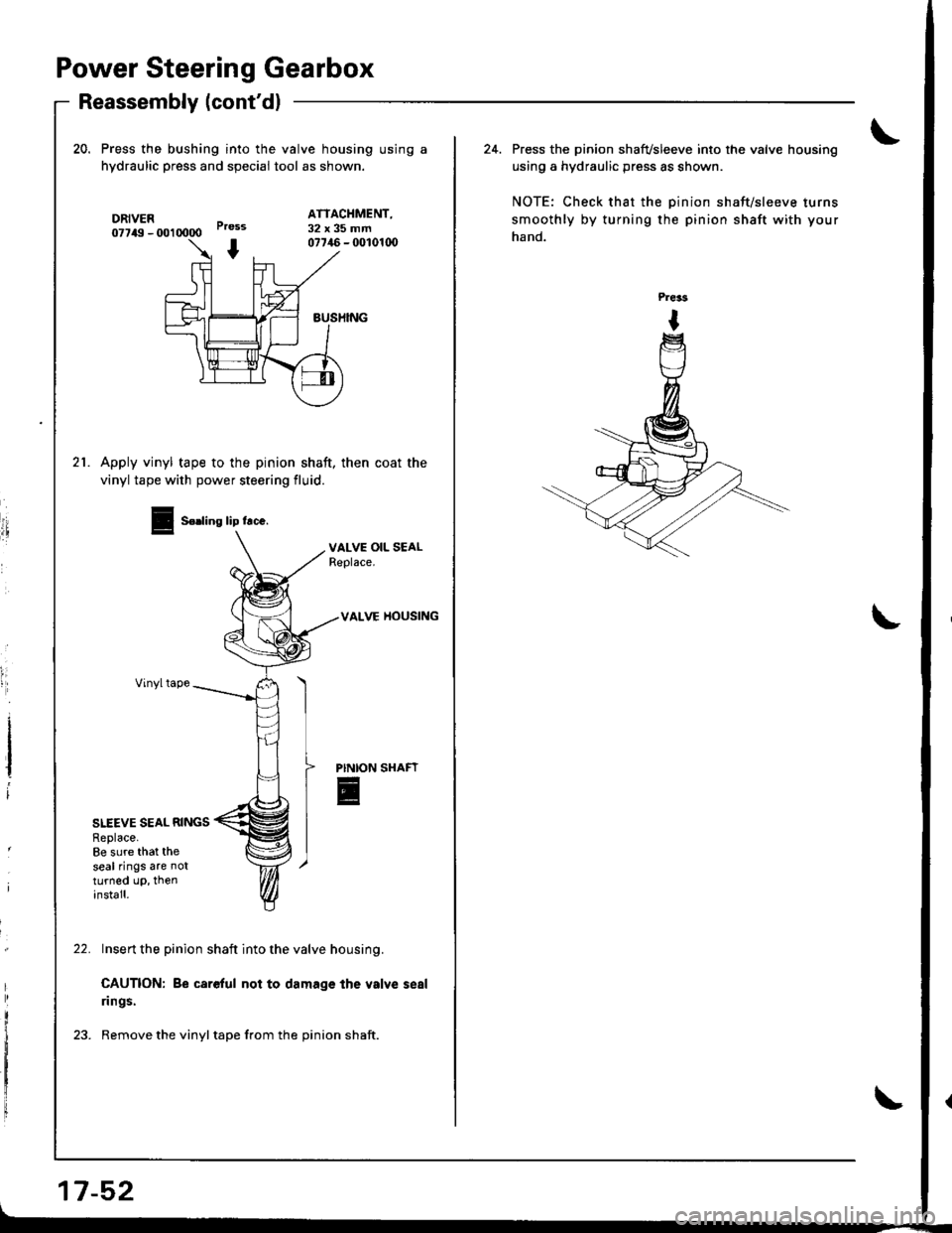
20. Press the bushing into the valve housing using a
hydraulic press and speciai tool as shown.
DRIVER07749 - U)l 0000
ATTACHMENT,32x35mmPress
I07746 - fi)l01(x)
sUSHING
21.Apply vinyl tape to the pinion shaft, then coat the
vinyl tape with power steering fluid.
I
i
I
VALVE OIL SEALReplace.
VALVE HOUSING
Vinyltape
PINION
E
SITEVE SEAL RINGSReplace.8e sure that theseal rings are notturned up, theninstall.
Insert the pinion shaft into the valve housing.
CAUTION: Be careful not to damage the valve seal
rings.
Remove the vinyl tape from the pinion shaft.
Seding lip lrce.
17-52
24. Press the pi.ion shafvsleeve into the valve housing
using a hydraulic press as shown.
NOTE: Check that the pinion shaft/sleeve turns
smoothly by turning the pinion shaft with your
hand.
Page 731 of 1681
lnstallation
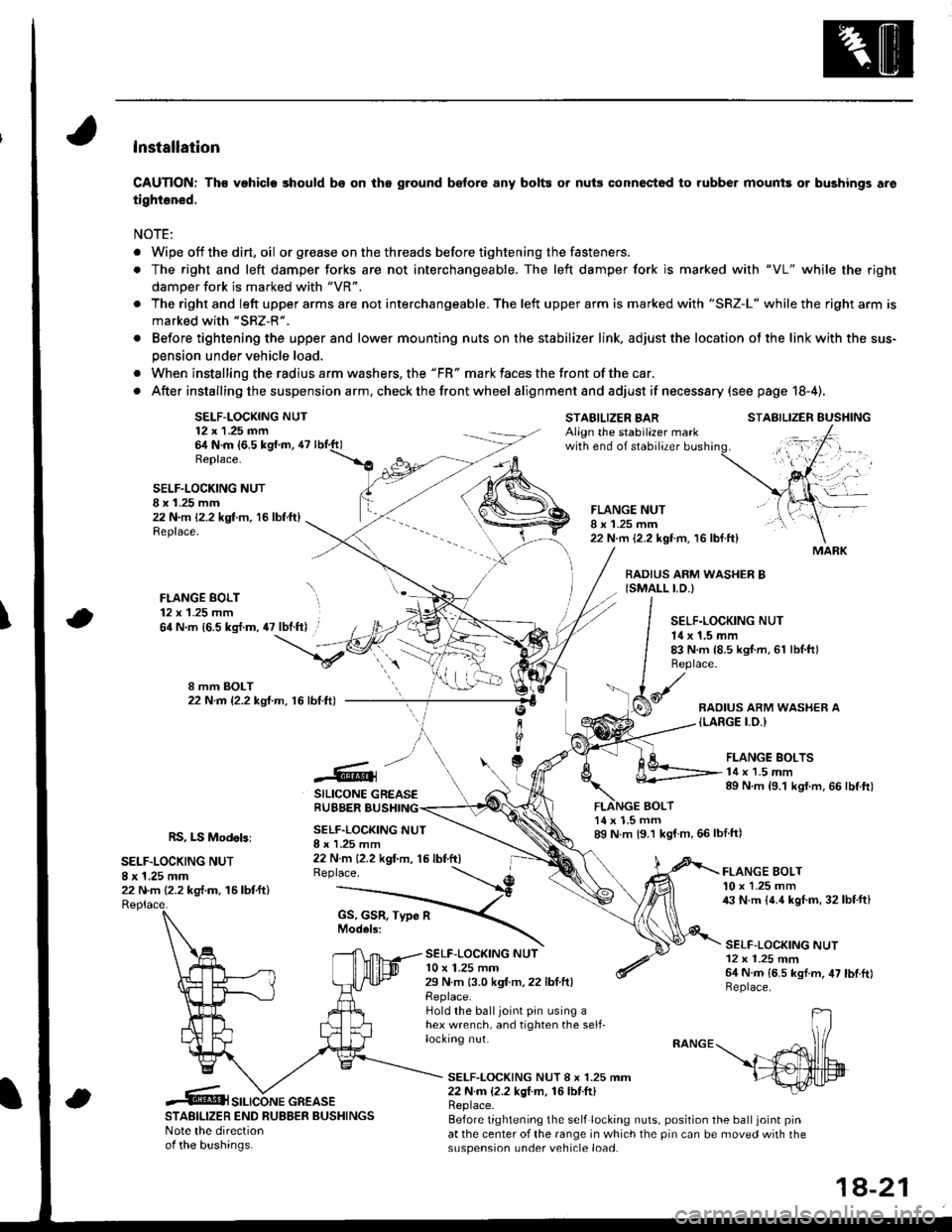
CAUTION: Th€ vehiclo should bs on the ground b€fore any bolts or nuis connectod to rubber mounis or bushings aro
tightened.
NOTE:
. Wipe off thedirt,oil or gr€ase on the threads before tightening the fasteners.
. The right and left damper forks are not interchangeable. The left damper fork is ma.ked with "VL" while the righr
damoer fork is marked with "VR".
. The right and left upper arms are not interchangeable. The left upper arm is marked with "SRZ-L" while the right arm is
marked with "SRZ-R".
. Before tightening the upper and lower mounting nuts on the stabilizer link, adjust the location ot the link with the sus-
pension under vehicle load.
. When installing the radius arm washers, the "FR" mark faces the front ofthe car.
. After installing the suspension a rm, check the front wheel alignmentand adjust if necesssry (see page 18-4).
SELF-LOCKING NUT12 x 1.25 nn64 N.m {6,5 kg{.m, 47Replace.
STABILIZER BARAlign the stabilazer markwith end of stabilizer
BOLT
STABILIZER EUSHING
SELF.LOCKING NUTI x 1.25 mm22 N.m 12.2 kgt m, 16 lbf.ft)Replace.
FLANGE BOLT12 x 1.25 mm
FLANGE NUTI x 1.25 mm22 N.m {2.2 kgt m. 16 lbf.ft}
BADIUS ARM WASHER B{SMALL I.D.)
\64 N.m {6.5 kg{.m, 47 lbt.ft) .SELF.LOCKING NUT14 x 1.5 mm83 N.m {8.5 kgI.m, 61 lbl.ftlReplace.
RAOIUS ARM WASHER A{LARGE I.O.I
.@]
SILICONE GREASERUBBER BUSHING
FLANGE BOLTS14 x 1.5 mm89 N.m {9.1 kgf.m, 66 lbtft)
RS, LS Modebi
SELF.LOCKING NUT8 x 1.25 mm22 N.m (2.2 kg,f.m. 16lbtftl
SELF.LOCKING NUTI x I .25 mm22 N m {2.2 kgt'm, 15 lbf.ft)Replace.
14 x 1.5 mm89 N m {9.1 kgf m,66lblft)
SELF-LOC(ING NUTl0 x 1.25 mm29 N.m 13.0 kgf.m,22 lbtftlReplace.Hold the balljoint pin using ahex wrench, and tighten the self-locking nut.
FLANGE BOLT10 x 1.25 mm43 N.m {4.4 kgl.m, 32lbf.ft}
SELF-LOCKING NUT12 x 1.25 mm64 N.m {6.5 kgf.m, 47 lbtftlReplace.
SELF-LOCKING NUT 8 x 1.25 mm22 N.m {2.2 kgI m, 16lbf.ft)
STABILIZER END RUBBER BUSHINGSNote the directionof the bushinas.
Replace.Before tightening the self locking nuts, position the ball joint pinat the center of the range in which the pin can be moved with thesuspension under vehicle load.
MARK
SILICONE GREASE
1A-21
Page 732 of 1681
Front Damper
FLANGE BOLT10 x'1.25 mm
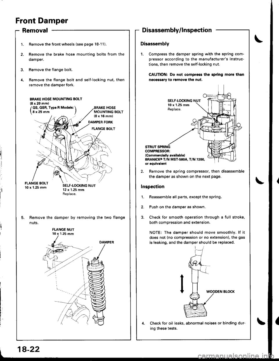
1.
4.
Removal
Remove thefrontwheels (see page 18-'11).
Remove the brake hose mounting bolts from the
damper.
Remove the flange bolt.
Remove the flange bolt and self-locking nut, then
remove the damper fork.
MOUNTING BOLT{8 x 16 mm)
Disassembly/lnspection
Disassembly
1. Compress the damper spring with the spring com-
pressor according to the manufacturer's instruc-
tions. then remove the self-locking nut.
CAUTION: Do nol compros3 tho 3pring morc than
nocessary to romovo th€ nut.
DAMPER FORK
FLANGE BOLT
SELF.LOCKING10 x 1.25 mmReplace.
COMPRESSORIlComm.rci.lly .Yrll.blclARAN|CKO T/N MST-580A, T/N 72IX',or aouivalant
Remove the damper by removing the two flange
n uts.
2, Remove the spring compressor, then disassemble
the damper as shown on the neld page.
Inspection
1. Reassemble all parts, exceptthe spring,
2, Push on the damper as shown.
3. Check for smooth operation through a full stroke,
both compression and extension.
NOTE: The damper should move smoothly. lf it
does not (no compression or no extension), the gas
is leaking, and the damper should be replaced.
Check for oil leaks, abnormal noises or binding dur-
ing these tests.
BMKE HOSE MOUNTING BOLT(8 x 20 mml
/GS, GSR, Type R Mod6ls: \l8x25mm I
18-22
Page 747 of 1681
Disassembly/lnspection
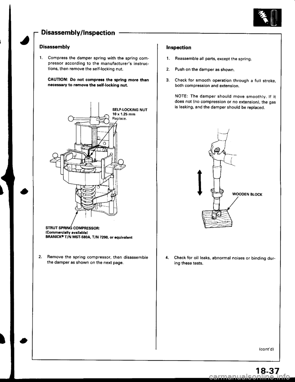
Disassembly
1. Compress the damper sp.ing with the spring com-pressor according to the manufacturer's instruc-
tions, then remove the self-locking nut.
CAUTION: Do not compre3s the spring more thannecessary to removo th€ sslf-locking nut.
SELF.LOCKING NUT10 x '1.25 mmReplace.
COMPRESSOR:(Comm.rcially.v.il.blol
BRANICKo T/N MST-580A, T/N 72dt, or.quiv.t.nr
Remove the spring compressor, then disSssemble
the damper as shown on the next page.
Inspection
1. Reassemble all parts, except the spring.
2. Push on the damper as shown.
3. Check for smooth operation through a full stroke,both compression and sxtension.
NOTE: The damper should move smoothly. lf it
does not (no compression or no enension), the gas
is leaking. and the damper should be replaced.
WOODEN BLOCK
4.Check tor oil leaks. abnormal noises or binding dur-ing these tests.
(cont'd)
18-37
Page 880 of 1681
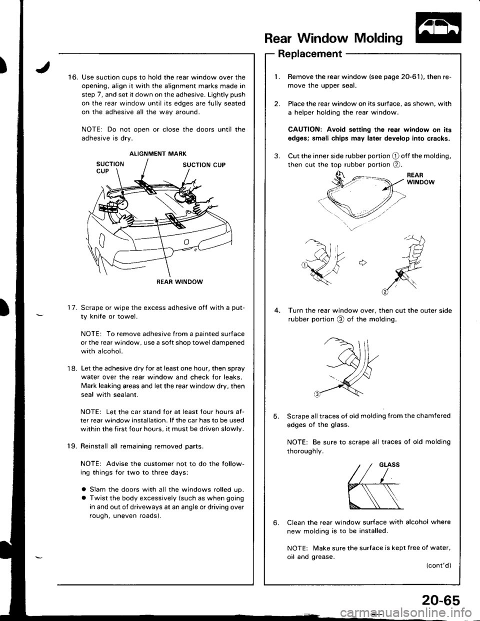
)Use suction cups to hold the rear window over the
opening, align it with the alignment marks made in
step 7, and set it down on the adhesive. Lightly push
on the rear window until its edges are fully seated
on the adhesive all the way around.
NOTE: Do not open or close the doors until the
adhesive is dry.
Scrape or wipe the excess adhesive ofl with a put-
ty knife or towel.
NOTE: To remove adhesive from a painted surface
or the rear window, use a soft shop towel dampened
with alcohol.
Let the adhesive dry for at least one hour, then spray
water over the rear window and check lor leaks.
Mark leaking areas and let the rear window dry, then
seal with sealant.
NOTE: Let the car stand tor at least four hours at-
ter rear window installation. lf the car has to be used
within the first four hours, it must be driven slowly.
all remaining removed parts.
NOTE: Advise the customer not to do the tollow-
ing things for two to three days:
a Slam the doors with all the windows rolled up.
a Twist the body excessively (such as when going
in and out of driveways at an angle or driving over
rough, uneven roads).
Rear Window Molding
2.
3.
6.
Replacement
Remove the rear window (see page 20-61), then
move the uoDer seal.
Place the rear window on its surface, as shown, v
a helper holding the rear window.
CAUTION: Avoid setting th6 real window on
edges; small chips may later develop into crac
Cut the inner side rubber ponion O off the moldi
then cut the top rubber portion @.
to.
Turn the rear window over, then cut the outer
rubber portion O of the molding.
17.
'1 8.
Scrape all traces of old molding from the cl
edges of the glass.
NOTE: Be sure to scrape all traces of old
thorough ly.
Clean the rear window surface with alcohol
new molding is to be installed.
NOTE: Make sure the surlace is kept free of
oil and grease.
mold19.
ALIGNMENT MARK
REAR WINDOW
w on ils
cracks.
molding,
side
chamfered
Ing
where
water,
)ont'd)
20-65
Page 888 of 1681
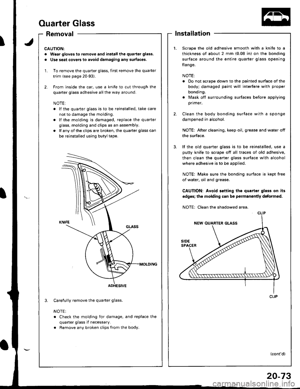
Ouarter Glass
Removallnstallation
1.Scrape the old adhesive smooth with a knife to a
thickness of about 2 mm (0.08 in) on the bonding
surface around the entire quarter glass opening
flange.
NOTE:
. Do not scrape down to the painted surface ol the
body; damaged paint will interfere with proper
bonding.
. Mask off surrounding surfaces before applying
primer.
Clean the body bonding surface with a sponge
dampened in alcohol.
NOTE: After cleaning, keep oil, grease and water off
the surface.
lf the old quarter glass is to be reinstalled. use a
putty knife to scrape off all traces of old adhesive,
then clean the quarter glass surface with alcohol
where adhesive is to be applied.
NOTE: Make sure the bonding surface is kept free
of water, oil and grease.
CAUTION: Avoid s6tting tho qurrtsr glass on its
edges; th€ molding can be permanently dstormed.
NOTE: Clean the shadowed area.
3.
CLIP
(cont'd)
CAUTIONi
. Wear gloves to remove and install the quarter glass.
. Use seat covers to avoid dsmaging any surfaces.
1. To remove the quarter glass, first remove the quarter
trim (see page 20-93).
2. Frcm inside the car, use a knife to cut through the
quarter glass adhesive all the way around.
NOTE:
o lf the quarter glass is to be reinstalled, take care
not to damage the molding.
. lf the molding is damaged, replace the quarter
glass, molding and clips as an assembly.
. lf any of the clips are broken, the quarter glass can
be reinstalled using butyl tape.
Carefully remove the quarter glass.
NOTE:
. Check the molding for damage, and replace the
quaner glass if necessary.
. Remove any broken clips from the body.
3.
ADHESIVE
Page 1032 of 1681
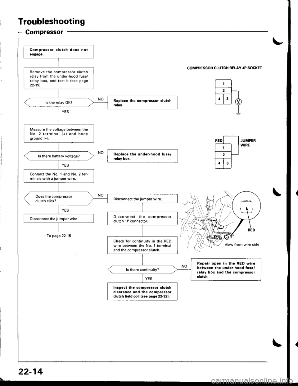
Troubleshooting
- Compressor
Remove the compressor clutchrelay trom the unde.hood tuse/relay box, and test it {see page
22-19t.
Measure the voltage beNveen theNo.2 terminal (+) and bodyground (-).
ls there battery voltage?
Connect the No. 1 and No. 2 terminals with a jumper wire.
Discon nect the compressorclutch 1P conoector.
Check lor continuity in the REDwire betlveen the No. 1 terminaland the compressor clutch.
Reprir open in tha BED wirabotwoon th6 undar-hood fusc/rolay box and lhs comp.osrorclutch.
In3p6ct th€ compre3sor clulchclear'nc€ and the comDressorcfutch ti€fd coil (se€ ptge22-321.
\-
COMPRESSOR CLUICH RELAY 'P SOCKET
JUMPERWIRE
\
To page 22-15
22-14
\
Page 1041 of 1681
J
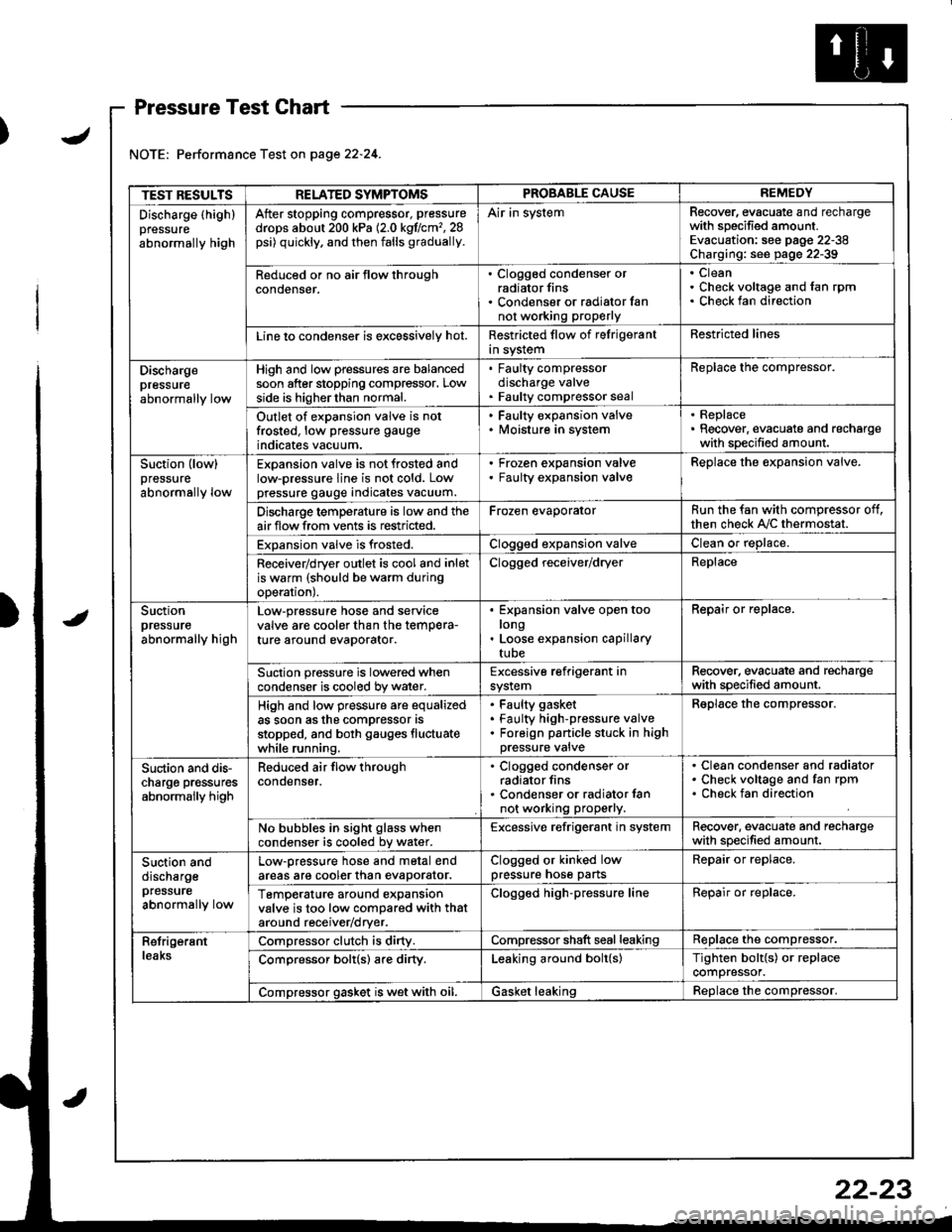
Pressure Test Chart
Performance Test on page 22.24.
TEST RESULTSRELATED SYMPTOMSPROBABLE CAUSEREMEDY
Discharge (highlpressure
abnormally high
After stopping compressor, pressure
drops about 200 kPa (2.0 kgflcm'�,28psi) quickly, and then falls gradually.
Air in systemRecover, evacuate and rechargewith specified amount.Evacuation: see pag€ 22-38Charging: see page 22-39
Reduced or no air tlow throughconoenser.
. Clogged condenser orradiator fins. Condenser or radialor fannot working proPerly
CleanCheck voltage and fan rpmCheck fan direction
Line lo condenser is excessively hot.Restricted flow of felrigerantin systemRestricted lines
Dischargepressureabnormally low
High and low pressures are balancedsoon after stopping compressor. Lowside is higherthan normal.
. Faulty compressordischarge valve. Faulty compressor seal
Replace the compressor.
Outlet of expansion valve is notfrosted, low pressure gauge
indicates vacuum.
. Faulty expansion valve. lvloisture in system
. Replace. Recover, evacuate and rechargewith specified amount.
Suction (low)pressure
abnormally low
Expansion valve is not frosted andlow-pressure line is not cold. Lowpressure gauge indicates vacuum.
Frozen expansion valveFaulty expansion valveReplace the expansion valve.
Discharge temperature is low and theairflow from vents is restricted.Frozen evaporatorRun the fan with compressor off,then check A,/C thermostat.
Expansion valve is frosted.Clogged expansion valveClean or replace.
Receiver/dryer outlet is cool and inletis warm (should be warm duringoperal|onJ.
Clogged receiver/dryerReplace
Suctionpressureabnormally high
Low-pressure hose and seryicevalve are cooler than the temPera-ture around evaporator.
Expansion valve open toolongLoose expansion capillarytube
Repair or replace.
Suction pressure is lowered whencondenser is cooled by water.Excessive refrigerant insystemRecover. evacuate and rechargewith specified amount.
High and low pressure are equalizedas soon asthe compressor asstopped, and both gauges fluctuatewhile running.
Faulty gasket
Faulty high-pressure valveForeign panicle stuck in highpressure valve
Reolace the comDressor.
Suction and dis-charge pr€ssuresabnormally high
Reduced air flow throughcondenser.
. Clogged condenser orradiator fins. Condenser or radiator lannot working properly.
Clean condenser and radiatorCheck voltage and fan rpmCheck fan direction
No bubbles in sight glass whencondenser is cooled bv water.Excessive refrigerant in systemRecover. evacuate and rechargewith specified amount.
Suction anddischargepfessure
abnormally low
Low-pressure hose and metal endareas are cooler than evaDorator.Clogged or kinked lowpressure hose partsRepair or replace.
TemP€rature around expansionvalve is too low compared with thataround receiv€r/dryer.
Clogged high-pressure lineRepair or replace.
RetrigerantleaksCompressor clutch is dirty.Compressor shaft seal leakingReplace the compressor.
Comoressor bolt(s) are dirty.Leaking around bolt(s)Tighten bolt{s) or replacecompressor.
Compressor gasket is wet with oil.Gasket leakingReolace the comoressor.
22-23
Page 1050 of 1681
Compressor
Clutch Inspection
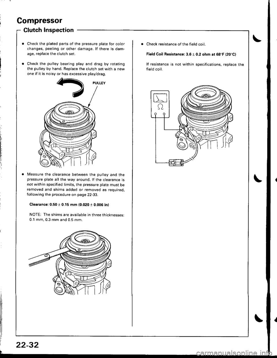
Check the plated parts of the pressure plate for color
changes, peeling or other damage. lf there is dam-
age, replace the clutch set.
Check the pulley bearing play and drag by rotating
the pulley by hand. Replace the clutch set with a new
one if it is noisy or has excessive play/drag.
Measure the clearance between the Dullev and thepressure plate all the way around. lf the clearance is
not within specified limits, the pressure plate must beremoved and shims added or removed as required,following the procedure on page 22-33.
Clearanca: 0.50 t 0.15 mm (0.020 r 0.006 in)
NOTE; The shims are available in three thicknesses:
0.1 mm, 0.3 mm and 0.5 mm.
22-32
Check resistance of the field coil.
Field Coil Resistance: 3.6 1 0.2 ohm at 68'F {20'C)
lf resistance is not within specifications, replace the
field coil.
Page 1052 of 1681
Compressor
a
a
Clutch Overhaul (cont'dl
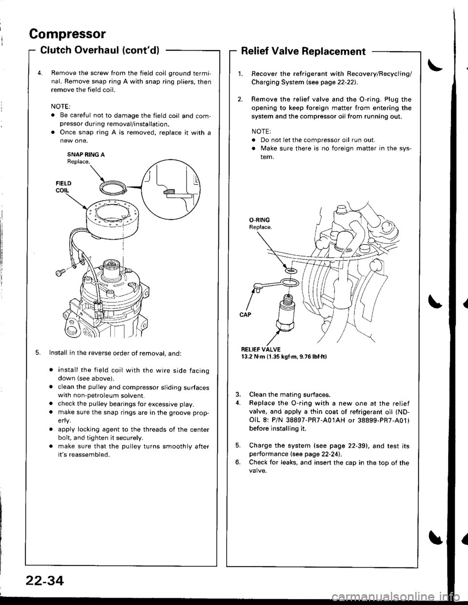
Remove the screw from the field coil ground termi,
nal. Remove snap ring A with snap ring pliers, then
remove the field coil.
. Be careful not to damage the field coil and com-presso. during removal/installation.
. Once snap ring A is removed, replace it with a
SNAP RING AReplace.
5. Install in the reverse order of removal, andl
install the field coil with the wire side facing
down (see above).
clean the pulley and compressor sliding surfaceswith non-petroleum solvent.
check the pulley bearings for excessive play.
make sure the snap rings are in the groove prop-
efly.
apply locking agent to the threads of the center
bolt, and tighten it securely.
make sure that the pulley turns smoothly after
it's reassembled.
Relief Valve Replacement
Recover the refrigerant with Recovery/Recycling/
Charging System lsee page 22-221.
Remove the relief valve and the O-ring. Plug the
opening to keep foreign matter from entering the
system and the compressor oil from running out,
NOTE:
. Do not let the compressor oil run out.
. Make sure there is no foreign matter in the sys-
tem.
RELIEF VALVE13.2 N.m (1.35 kgf.m,9.76lbtft)
3. Clean the mating surfaces.
4. Replace the O-ring with a new one at the relief
valve, and apply a thin coat of refrigerant oil (ND-
OIL 8: P/N 38897-PR7-A01AH or 38899-PR7-A01)
before installing it.
5. Charge the system (see page 22-39), and test itsperformance (see page 22-241.
6. Check for leaks, and insert the cap in the top of the
FIELD
t\I lu
B _t_:---\-lr
\,/
22-34