ECO mode HONDA INTEGRA 1998 4.G Owner's Guide
[x] Cancel search | Manufacturer: HONDA, Model Year: 1998, Model line: INTEGRA, Model: HONDA INTEGRA 1998 4.GPages: 1681, PDF Size: 54.22 MB
Page 1554 of 1681
- How the Circuit Works
The security system control unit has a 3 position
switch: Manual. Auto. and Auto Lock. Here's what
happens when you arm the system, regardless ol
the switch position:
o The parking lights will flash once.
. The security indicator will flash once per second
after the system is armed.
With the switch in the Manual position, the security
system can only be armed by using the remote
control transmitter, After you remove the key from
the ignition and close all doors, the hood (if
equipped with the optional hood switch), the hatch
or trunk. Dress the lock button on the transmitter
and the system will arm (if the system is in the beep
sound mode, the horn will sound once). The doors
will automatically lock when the system is armed.
With the switch in the Auto position, the security
system will arm itself within about 20 seconds after
you turn the engine off, remove the key from the
ignition, and close the halch or trunk, the hood (if
equipped with the optional hood switch), or last
door. lf a door is opened during the 2o-second exit
delay time, the timer will reset itself . The remote
control transmitler can still be used to arm the
system with the switch in Auto position (see manual
for details).
With the switch in Auto Lock position, the security
system will arm itself and lock the doors about 20
seconds after you turn the engine of{, remove the
key from the ignition, and close the hatch or trunk,
the hood (if equipped with the optional hood
switch), or last door. lf a door is opened during the
2o-second exit delay time, the timer will reset. The
remote control transmitter can still be used to arm
the system in the Auto Lock position.
Triggering the Alarm
After the security system is armed, the sound ot
breaking glass or the opening of a door, hood,
hatch or trunk will trigger the alarm, and cause
the following:
r The horn will sound for30 seconds.
The optional siren will sound lor 60 seconds.
. The parking lights will flash.
. The security indicator LED will flash twice per
second.
. The starter will be disabled.
At the end of the alarm cycle, the system will
automatically rearm.
Disarming the Security System
There are two ways to disarm the security system:
. With the transmitter
o With the disarm/valet switch
When the system is disarmed, regardless of the
method used, the parking lights will flash two times if
the alarm has not been triggered and three times if
the alarm has been triggered. To disarm the system
with the transmitter, press the unlock button (if the
system is in the beep sound mode, the horn will
sound two times if the alarm has not been triggered,
however, will sound three times if the alarm has
been triggered). The driver's door will unlock
(pressing the unlock button twice will unlock all
doors).
To disarm the security system using the
disarm/valet switch, enter the car and turn the
ignition switch to ON (ll) then press the disarm/valet
switch button. lf you open the door when the control
unit switch is in Auto or Auto Lock, a 2o-second
entry delay will give you time to disarm the system.
However, when the system is armed by the
transmitter, the entry delay time is changed to zero
seconds, and the alarm is triggered as soon as you
oDen the door.
ldentifying Tripped Sensors
The system will indicate the sensor which triggered
the alarm through the security indicator LED. While
sitting inside the vehicle wlth the key out of the
ignition switch, all doors, the hood (if equipped with
the optional hood swilch), the hatch or trunk must be
closed. Press and hold the disarm/valet switch.
Press the lock button and then the unlock button of
the transmitter. Belease the disarm/valet switch. The
status LED will blink according to the following code:
Sensors
Door
Trunk/Hatch
System Switches
Glass Breakage
Hood (Optional)
Number ol Flashes
1 blink, pause, repeat
2 blinks, pause, repeat
3 blinks, pause, repeat
4 blinks, pause, repeat
5 blinks, pause, repeat
For further operating instructions and troubleshooting,
see the security system owner's manual.
133-5
Page 1609 of 1681
)rD
)Ic418
c424
c423
c425
c448
c445c447
Cil46c416c421
c422
c417c420 c419
c415
G401
c412
c441 C442 C451
c41t
c438
UNDER-DASHFUSE/RELAY BOX
I
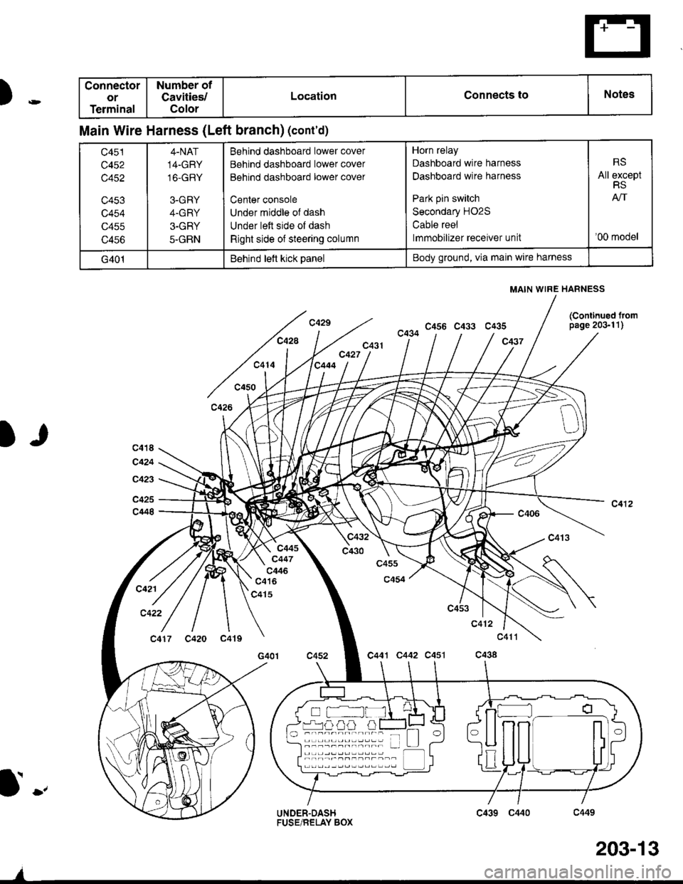
Connector
or
Terminal
Number of
Cavities/
Color
LocationConnects toNotes
Main Wire Harness (Left branch) (cont'd)
c451
c452
c452
c453
c454
c455
c456
4.NAT
14-GRY
16-GRY
3-GRY
4.GRY
3-GRY
5-GRN
Behind dashboard lower cover
Behind dashboard lower cover
Behind dashboard lower cover
Center console
Under middle of dash
Under leit side of dash
Right side of steerang column
Horn relay
Dashboard wire harness
Dashboard wire harness
Park pin switch
Secondary H02S
Cable reel
lmmobilizer receiver unit
RS
All exceptRS
'00 model
G401Behind lett kick panelBody ground, via main wire harness
MAIN WIRE HARNESS
o -,i---nnrnr-n
(Continued lrompage 203-11)
c439 C440
203-13
Page 1640 of 1681
Under-hood Emissions Gontrol Label
Emission GrouP ldentification
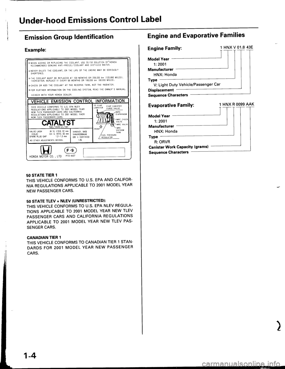
Example:
50 STATE TIER 1
THIS VEHICLE CONFORMS TO U.S. EPA AND CALIFOR-
NIA REGULATIONS APPLICABLE TO 2OO1 MODEL YEAR
NEW PASSENGER CARS.
50 STATE TLEV + NLEV (UNRESTRICTEDI:
THIS VEHICLE CONFORMS TO U.S. EPA NLEV REGULA-
TIONS APPLICABLE TO 2OO1 MODEL YEAR NEW TLEV
PASSENGER CARS AND CALIFORNIA REGULATIONS
APPLICABLE TO 2OO1 MODEL YEAR NEW TLEV PAS.
SENGER CARS.
CANADIAN TIER 1
THIS VEHICLE CONFORMS TO CANADIAN TIER 1 STAN.
DARDS FOR 2OO1 MODEL YEAR NEW PASSENGER
HONDA l/0T0R c0. , LTD P72-401
>wHEN ADDTNG oR FEPtActNG THE co0LANT, usE 50,/50 soLUr oN oF'HoNDARECOMMTNDED GENUINE ANT -FREIZE,/COOtANT AND DIST LLED WATEF'
>NEVEfl DILUTE THE COOtANT, OR IHE LIFE OF THE ENGINF MAY BE SER]OUSLYSHORTENTO.
>THE COoLANT MUST BE BEPLACED AT I20 MONTHS OR 200.000 km (120 000 [,| LtS]'rnirilrren, B€pLAcE rT EvEFY 60 [roNTHs oR 100.000 km (60 000 [ilLEs)'
>CHEC( OR ADD THE COOLANI AT THE RESERVE TANK. NOT THE RADIATOF'
>FOR FI,JRTHER INFORMATION ON ]HE COOL]NG SYSTEM. READ THE OWNEN'S MANUAL'
ICHECK WITH YOUR HONOA DEALER,
ll,5lil, 5;i;,'iX;';'THIS VTH CtE CONFOF[IS TO U.S. EPA NLEVREGULATIONS APPL]CABLE TO 2OO] MODEL YTAsNEW TLTV PASSENGEF CAFS AIID CAL]FORNIAREGUTATIONS APPLICABLE TO 2OO] MOOET YAERNEW TLEV PASSENGER CARS.
IHNXVOI, 813FI HNXROO99AAKO8O II CERIIFIED1.81
VATVE LASH N:0. l/10. 02 mm(COLD) EX|0 19i0 02 mmSPARK PLUG GAP 1.2-1.3 mmIO OTHER ADJUSIMENIS NIEDTO,
Engine and EvaPorative Families
Engine Family:1HNXV01.8 43E
Model Year
1:2001
Manufacturer
HNX: Honda
Type
V: Light Duty Vehicle/Passenger Car
Displacement
Sequence Gharasters
Evaporative FamilY:1 HNX R OO99 AAK
Model Year
1:2001
Manufacturer
HNX: Honda
Type
R: ORVR
Ganister Work CaPacitY (gramsl
Sequence Characters
1-4
Page 1641 of 1681
Revised Component Terms
\
\
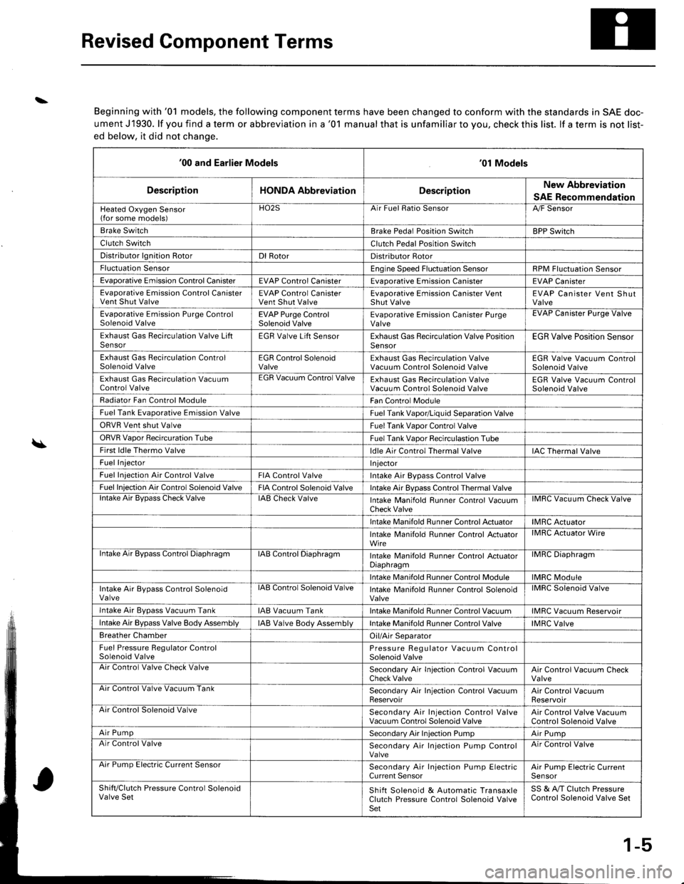
Beginning with '01 models, the following component terms have been changed to conform with the standards in SAE doc-
ument J1930. lf you find a term or abbreviation in a '01 manual that is unfamiliar to you, check this list. lf a term is not list-
ed below, it did not chanqe.
'00 and Earlier Models'01 Models
DescriptionHONDA AbbreviationDescriptionNew Abbreviation
SAE Recommendation
Heated Oxygen Sensor(for some models)HO2SArr ruet llalto )ensorA,/F Sensor
Brake SwitchBrake Pedal Position SwitchBPP Switch
Clutch SwitchClutch Pedal Position Switch
Distributor lgnition RotorDl RotorDistributor Rotor
Fluctuation SensorEngine Speed Fluctuation SensorRPM Fluctuation Sensor
Evaporative Emission Control CanisterEVAP Control CanisterEvaDorative Emission CanisterEVAP Canister
Evaporative Emission Control CanisterVent Shut ValveEVAP Control CanisterVent Shut ValveEvaporative Emission Canister VentShut ValveEVAP Canister Vent ShutValve
Evaporative Emission Purge ControlSolenoid ValveEVAP Purge ControlSolenoid ValveEvaporative Emission Canister PurgeValveEVAP Uanister Purge Valve
Exhaust Gas Recirculation Valve LiftSensorEGR Valve Lift SensorExhaust Gas Recirculation Valve PositionSensorEGR Valve Position Sensor
Exhaust Gas Recirculation ControlSolenoid ValveEGR Control SolenoidValveExhaust Gas Recirculation ValveVacuum Control Solenoid ValveEGR Valve Vacuum ControlSolenoid Valve
Exhaust Gas Recirculation VacuumControl ValveEGR Vacuum Control ValveExhaust Gas Recirculation ValveVacuum Control Solenoid ValveEGR Valve Vacuum ControlSolenoid Valve
Radiator Fan Control ModuleFan Control Module
Fuel Tank Evaporative Emission ValveFuel Tank Vapor/Liquid Separation Valve
ORVR Vent shut ValveFuel Tank Vaoor Control Valve
ORVR Vaoor Recircuration TubeFuel Tank Vaoor Recirculastion Tube
First ldle Thermo Valveldle Air Control Thermal ValveIAC Thermal Valve
Fuel InjectorI njector
Fuel Iniection Air Control ValveFIA Control ValveIntake Air Bypass Control Valve
Fuel Injection Air Control Solenoid ValveFIA Control Solenoid ValveIntake Air Bypass Control Thermal Valvelntake Air BvDass Check ValveIAB Check ValveIntake Manifold Runner Control VacuumCheck ValveIMRC Vacuum Check Valve
Intake Manifold Runner Control ActuatorIMRC Actuator
Intake Manifold Runner Control ActuatorWireIMRC Actuator Wire
ntake Air Bypass Control DiaphragmIAB Control DiaphragmIntake Manifold Runner control ActuatorDiaphragmilvrr1u urapnragm
Intake Manifold Runner Control ModuleIMRC Module
Intake Air Bypass Control SolenoidValvelAts Control Solenoid ValveIntake Manifold Runner Control SolenoidValveIMRC Solenoid Valve
Intake Air Bvpass Vacuum TankIAB Vacuum TankIntake Manifold Runner Control VacuumIMRC Vacuum Reservoir
Intake Air Bypass Valve Body AssemblyIAB Valve Body AssemblVIntake Manifold Runner Control ValveIMRC Valve
Breather ChamberOil/Air Separator
Fuel Pressure Regulator ControlSolenoid ValvePressure Regulator Vacuum ControlSolenoid ValveAir Control Valve Check ValveSecondary Air In.jection Control VacuumCheck ValveAir Control Vacuum CheckValveArr Control Valve Vacuum TankSecondary Air Injection Control VacuumReservoirAir Control VacuumReservoirAir Control Solenoid ValveSecondary Air Injection Control ValveVacuum Control Solenoid ValveAir Control Valve VacuumControl Solenoid Valve
Air PumpSecondary Air Injection PumpAir PumpAir Control ValveSecondary Air Injection Pump ControlValveAir Control Valve
Arr rump tsreclnc uurrent bensorSecondary Air Injection Pump ElectricCurrent SensorAir Pump Electric CurrenlSensor
Shift/Clutch Pressure Control SolenoidValve SetShift Solenoid & Automatic TransaxleClutch Pressure Control Solenoid ValveSet
SS & A,/T Clutch PressureControl Solenoid Valve Set
1-5
Page 1642 of 1681
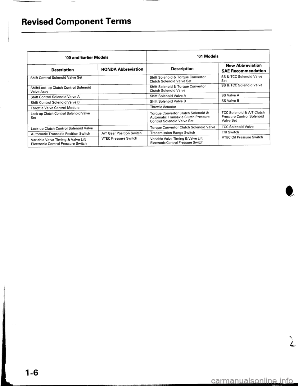
Revised Component Terms
'00 and Earlier Models'01 Models
DescriptionHONDA AbbreviationDescriptionNew Abbreviation
SAE Recommendation
Shift Control Solenoid Valve SetShift Solenoid & Torque ConvertorClutch Solenoid Valve SetSS & TCC Solenoid ValveSet
Shift/Lock-up Clutch Control SolenoidValve Assy
Shift Solenoid & Torque ConvertorClutch Solenoid Valve
SS & TCC Solenoid Valve
Shift Control Solenoid Valve AShift Solenoid Valve ASS Valve A
Shift Control Solenoid Valve BShift Solenoid Valve BSS Valve B
Throttle Valve Control ModuleThroftle Actuator
Lock-uo Clutch Control Solenoid ValveSetToroue Convertor Clutch Solenoid &Automatic Transaxle Cl utch PressureControl Solenoid Valve Set
TCC Solenoid & Av/T ClutchPressure Control SolenoidValve Set
Lock-uo Clutch Control Solenoid ValveTorque Convertor Clutch Solenoid ValveTCC Solenoid Valve
Automatic Transaxle Position SwitchA,/T Gear Position SwitchTransmission Range SwitchT/R Switch
Variable Valve Timing & Valve LiftElectronic Control Pressure Switch
VTEC Pressure SwitchVariable Valve Timing & Valve LiftElectronic Control Pressu re Switch
VTEC Oil Pressure Switch