ECO mode HONDA INTEGRA 1998 4.G Owner's Manual
[x] Cancel search | Manufacturer: HONDA, Model Year: 1998, Model line: INTEGRA, Model: HONDA INTEGRA 1998 4.GPages: 1681, PDF Size: 54.22 MB
Page 1419 of 1681
TRANSMISSION
I
I
T4
PGM-FIMAIN RELAYPage 23 ('98-'99)or 24 ( 00)
tl
tlL-J
* : '98-'99 Models
i---------\L---------J(- 10) r-- -;-;.11, (c408.)(- 23)10
'98- 99.. GS.R' l/odel
inrrarerrn i
I
I
.-- GS-R. TYPE.R
VEHICLESPEEDSENSORRADIATOBFAN SWITCH
and 63 2
tl
tlL-Jcl08
(vss)Page
PHATO 6IIITJ
I
I
33
I
I
c3o1 ;
10
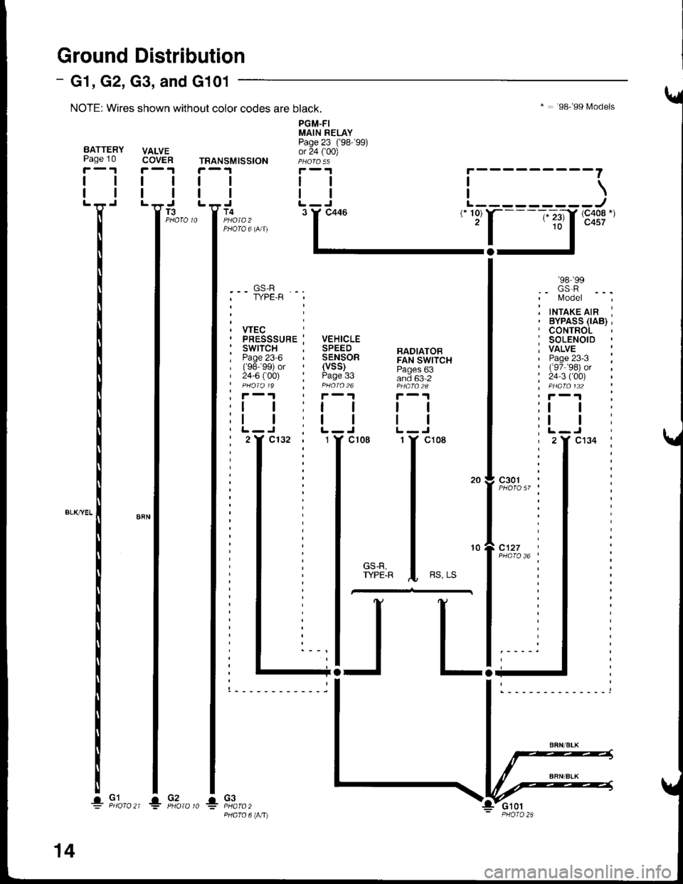
Ground Distribution
NOTE: Wires shown without color codes are black.
VALVECOVER
I
I
- G1, G2, G3, and G101
I
I
T3
BATTERYPage 10
r-'r
tl
ll'n'
I
I
I
I
I*-*rl
I
I
I
I
! F,to,o^_l1io,o,o *
14
Page 1420 of 1681
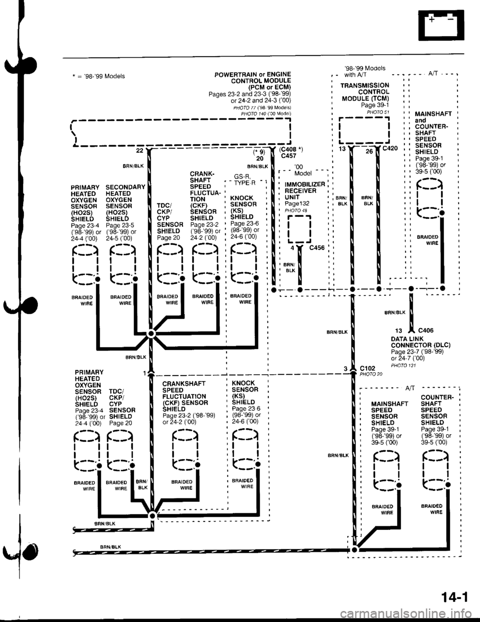
* = '98-'99 L4odelsPOWERTRAIN or ENGINECONTROL MOOULE(PCM or ECM)Paqes 23-2 and 23'3 ('98-'99)- or 24-2 and 24-3 ('00)
PHOTO // f98 99 Models)
'98' 99 l\4odels
TRANSMISSIONCONTROLMODULE (TCM)Page 39-1PBA|O 51
--".-- A/T.--,
PHA|A 144 100 Made )
rl\lI&------ ---------J
26'� I c4s7
L----J
c102PHO|O20
MAINSHAFTanoCOUNTER.SHAFTSPEEDSENSORSHIELDPage 39-1('98-'�gs) or39-s [oo)
COUNTER-SHAFTSPEEDSENSORSHIELDPage 39-1('98-'�sg) or3e-5 f00)
BBN/BLK
PRIMARY SECONDARYHEATEO HEATEOOXYGEN OXYGENSENSOR SENSOR(HO2S) (HO2S)SHIELD SHIELDPage 23-4 Page 23-5('98-'99) or ('98-'99) or24-4 ('�00) 24-5 f00)
AFN/BLK
PBIMARY 'l
HEATEDOXYGENSENSOR TDC/(HO2S) CKP/SHIELD CYPPaqe 23-4 SENSOR('96- 99) or SHIELD24 4 ('00) Page 20
BRN/BLK
CRANK- ne_FSHAFT . - ii'pilp -i
SPEEDFLUCTUA-
CKP/CYPSENSORSHIELOPage 20
l1
ll
k::!
T|ON 'KNOCK
(cKF} : SENSORSENSoR . (KS)SHTELD , SHIELDpaoe 23-2 ' Page 23'6(96- 99) or ' (98-99) or
24 2 (OOt : 24-6 ('�00)
r::)f::l i(::)
l::i iL:l
r::)
tt
tl
(- ,:o
BRATDED IWIFE I
lltl
k--'a
illBFAIDEOWIBEBFAIDEDWIRE
AFCRANKSHAFTSPEEDFLUCTUATION(cKF) SENSORSHIELDPage 23-2 (98-99)ot 24-2 (00)
. KNOCK, SENSOR,(Ks),SHIELD
| 1se:'ss; or, 24,6 ('�00)
ir::)
MAINSHAFTSPEEDSENSORSHIELDPage 39-1('s8-'99)or3e-s ('00)c:) r::)
I
I
k:::
ll
tl
.k
(::)
ll
tl
kIt::
I
I
a
(::)
tl
ll
(::::BRAIOEOBFN/BLKBNAIDEO
:l I;l I
BNAIDED
:kll::
' BFAIDEO
i: (::)
::l I,' I I
iiffil
.---a--,--o
I""","j-.!,
"oo.
DATA LINKcoNNECTOR (DLCIPage 23-7 ('S8-'99)or 24-7 ('00)
(DLC)
BFAIDEDWIFE
14-1
Page 1451 of 1681
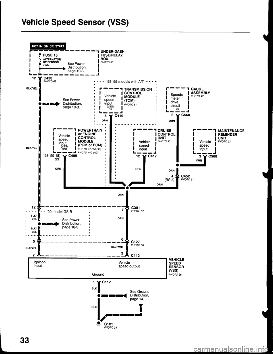
Vehicle Speed Sensor (VSS)
FUSE 15
.t UNDER.DASH
! SBiE/RELAY
'--- 98 99 models with A,rT ----
1
5
J^r""'See Groundarr< Diskibulion,
I o"o" t+
"'*l I
!r::'-'
c438
".,,::.x
POWERTRAIN '| ,,--,^,- | or ENGINEI l:li.:" a coNrRoLi ::J:" : MODULE :
i
'{is,
i!""""9;li"S, j
L---J pHaral&(oo)
ll
Vehiclespeedinput
c30t
CRUISECONTROLUNITtl
! y::g" II i,ifi- |L---J
-ir""'
MAINTENANCEREMINDERUNIT
(98-'9918) y. C409
c452
12
I BLK/. YEL
, BLK/I YEL
BLK'YEL
-'oomodel GS'R-----.
See Powera4 Distribution,
I
ease 1o-3.
x-----
l
c127
c1't2VEHICLESPEEOSENSOF(vss)PHOfO 26
lgnitioninputVehiclespoed output
Ground
33
Page 1456 of 1681
r--1 caucE I r--'t lGNlnoN
,l;:
DISTRIBUTORASSEMBLY
TESTTACHOMETERCONNECTOB
r--1 POWERTRAINTEST I lorENGlNETACHoMETER I I coNTRoL MoDULECONNECTOR | | (PCM or ECM)PHO|Q 36 L--J PHO\O 1aA
.:r"'' ::"r**
..1^"^, I
.-,1 ilo-;52 I*
l-!
t*"L________
l__j**" ililf,fj$8Blt?'; -^;." ! Y-I-- --'-r-----
.,,,I BLU I*-l s:a c1o9
. I "or, --.f r;'orc 'o
9,^::,,, ";f
t'ot'"
'ls":/",
Btu I aLU 2
---
"., I *, I
c3o6
!!",?ii:" 'l--.4n+,.
-"1--:1"-l
'00 Model"il
".',-- -'l cRUlsE
I RPtvl input I CONTROLI UNIT
Models
lPHora 55
I oisengage input Vehicle speed input rL - - - - - - - -*? =_-_-_-_-_-:_-_-_== = =_-_;ffcr--r i
M/r PNKI Air I; "Hf----;---
,
---.tf c417
*f "n^f
""" I :ffs:"ff:,
*oa,,"",*,,"",.---:l[i:].', uo-u=uo
/.1ff;i;lu:*r |
""!-
ii iit'diF' !--l
":"1",,,
"i-f t* ' """1 :ffs:"ff;
,.[:..
i'*f-i
li*'
I oaoe ,+ +
I ftf,ll,*r i;p-pT l ;.#i""�J:*^l
i i "'*l L'itliY#;"
b;'t
t----'{
non-,: pHOTO 56 - PHOTO 56
34-3
Page 1475 of 1681
![HONDA INTEGRA 1998 4.G Owners Manual ALK]^VEL
4YEVBLKc682
MODECONTROLMOTOR
LT GFNAVHT
YEVAEO
c682
69YEL
@
D6lro3tSsltch
le-
,
t_
t
\
\
\
I
I
I
,
I
I
>a
at
Vo.iSwhch
\F.
"a
HiDEFSwltch
"lf ttto
oBLK I
| !3!"u;;110 oo"on
".*l 1
W,rl HONDA INTEGRA 1998 4.G Owners Manual ALK]^VEL
4YEVBLKc682
MODECONTROLMOTOR
LT GFNAVHT
YEVAEO
c682
69YEL
@
D6lro3tSsltch
le-
,
t_
t
\
\
\
I
I
I
,
I
I
>a
at
Vo.iSwhch
\F.
"a
HiDEFSwltch
"lf ttto
oBLK I
| !3!"u;;110 oo"on
".*l 1
W,rl](/img/13/6069/w960_6069-1474.png)
ALK]^VEL
4YEVBLKc682
MODECONTROLMOTOR
LT GFNAVHT
YEVAEO
c682
69YEL
@
D6lro3tSsltch
le-
,
t_
t
\
\
\
I
I
I
,
I
I
>a
at
Vo.iSwhch
\F.
"a
HiDEFSwltch
"lf ttto
oBLK I
| !3!"u;;110 o'o'''"'on'
".*l 1'
W,rl-
61-1
Page 1477 of 1681
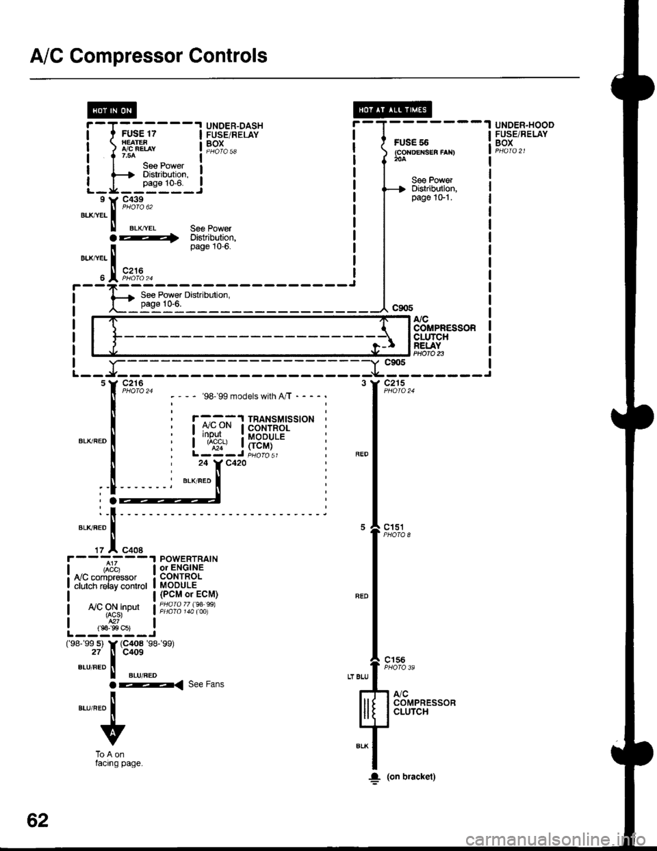
A/C Gompressor Controls
FUS€ 55(GoNDEXSEA fAN)204
UNDER.HOOOFUSE/RELAYBOX
@r-T------.I UNDER-DASHI t FUSE 17 I FUSE/RELAY
| ) LBEL, t19T^..
I I r.uo ^ _ l--*I I lee Power I: {--t Diskibdion. :
L_I_fiT_.!I Y C439
".^,tr. |
"'oto u'
ll erx,.ver 36€ Powera ---i Distribution,page tO-0.
BLX/YEL I
" IFi:,u.^
See PowerDislribution,page 1G'l .
NCCOMPR€SSORCLUTCHREI.AYPtloro n-Y c905
-*----------f
"*l'--
,1,*,
"-l
"ft:,,
lll[ 133,]+'"1F**
;f
I. (on bracket)
- '98199 models with A/T - - - -
r -^ ^-^:'l TRANSMTSSTONCONTROL: rr!P!I.. : MoDULE| ^;;', | (rcM)L-Z-J iuoro sr24 Y C420
BLK/RED
POWERTRAINor ENGINECONTROLMODULE(PCM or ECM)PHOfO 77 (94 99)ly'C ON inDut{ACS}
L--,S"s-i(98- 99 s) Y (C4o8 '�98-'�99)
27 tl C409
",-r,"ao II aLuneo
ar< ree Fans
ilaurneo I
v
ToAonlacrng page.
62
Page 1496 of 1681
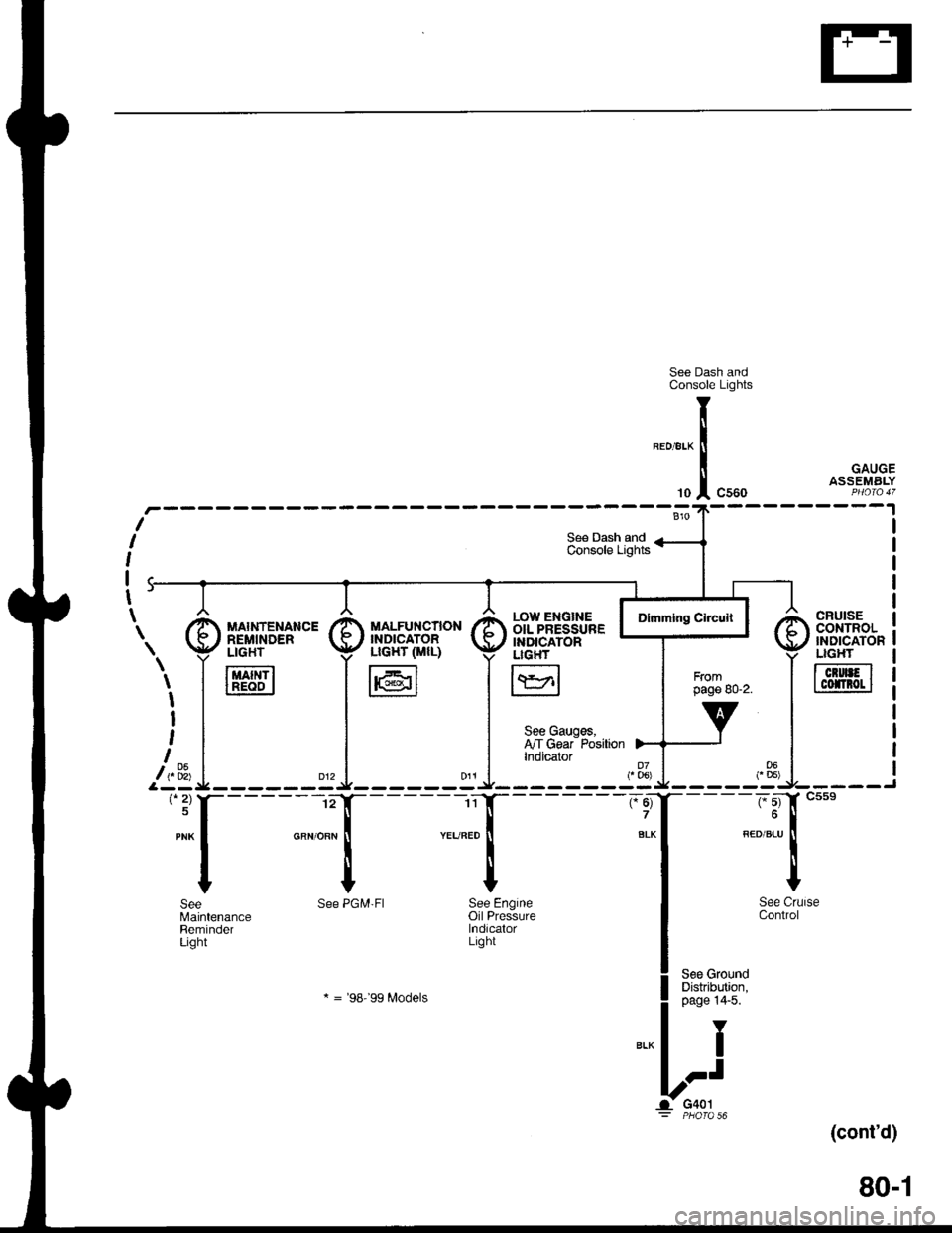
See Dash andConsole Lights
GAUGEASSEMBLY
(cont'd)
80-1
CRUISEcor{TRoL'NDICATONLIGHT
TcrurFlI cofnot I
r.ow ENGTNE IOIL PRESSURE IINDICATORLIGH'
I\YrlL:J
See Gauges,I'lT Gear PositionIndicator
"ff
I
See CrlControl
See GroundDistribution,page 14'5.
Y
I
.-t
G401PHO|O 56
T
li
'"1
See PGM'FI See Engineoil PressurelndicalorLight
* = '98-'�99 Modets
SeeMaintenanceReminderLight
\. I [,'d['*"' I il]i"fl".,B* I
i,1_* =i^ .l
'*f----l- :{
Page 1507 of 1681
Wiperffasher (contd)
- How the Circuit Works
When the ignition switch is in ON (ll) or START (lll),
battery voltage is applied to lhe windshield
wiper/washer switch, and the windshield wiper
motor.
Low Speed
When you turn the wiper switch to LO, the wiper
motor's low speed winding is grounded through the
BLU wire and the LO speed contacts of the wiper
switch at G401, and the wipers run at low speed.
ParUOfi
When you turn the wiper switch OFF, the integrated
control unit (PARK input) grounds the wiper motor
through the BLUMHT wire. The cam switch on the
motor signals the integrated control unit that the
wipers are in the PARK position; the control unit
then removes ground from the motor, and the
wipers stop in the PARK position.
High Speed
When the wiper switch is in Hl, the high speed
windings ol the windshield wiper motor are
grounded through the BLUI/EL wire and the Hl
contacts of the wiper switch at G401 , and the
wipers run at high speed.
Intermittent
When the wiper switch is in lNT, battery voltage is
applied through the YEUBLU wire to the integrated
control unit (lntermittent wiper ON input). The
integrated control unit (lntermittenvPark Wiper
Control) grounds the low speed windings of the
wiper motor and the wipers make a single sweep
every few seconds (See Low Speed above). When
the wiper returns to the PARK position, the park
switch applies battery voltage through the
BLUMHT wire to the integrated control unit (PARK
input), and the wipers stop in the PARK position.
91-2
Mist
When you pull the wiper switch down to MIST
position, the high speed windings of the wiper motor
are grounded through the BLU//EL wire and the
closed contacts of the mist switch at G401, and the
wipers make one pass across the windshield at high
speed. The PABKOFF tunction then takes over and
the wrpers stop in the PARK position.
Washer
When you pull the wiper switch toward you to turn on
the washer switch, battery voltage is applied to the
washer motor. The motor pumps fluid onto the
windshield until you release the lever. On models
with combined wiper/washer operation (Canada), the
integrated control unit (windshield washer ON input)
senses power al the BLI(GRN wire terminal and
runs the washer motor whenever the wioers run.
Reter to the Service irlanual (Section 23, Electrical)
for specific tests or troubleshooting procedures.
Page 1540 of 1681
Power Windows (conrd)
- How the Circuit Works
CAUTION: You could iniure your arms, hands,
or fingers if you unintentionally switch the
driver's window to "automatic down,' while
working in that door with the power on. Discon-
nect the window switch connector or the battery
when working in the driver's door.
System Description
The operation of the power windows is controlled by
the main switch in the power window masler switch.
When the main switch is in OFF, only the driver's
door window can be opened or closed. With the main
switch ON, all windows can be opened or closed
either by switches in the master panel, or switches in
the doors. The driver's window switch also has an
automatic down mode which is tumed on by pushing
the switch down to its second position.
The power windows are driven by reversible motors.
Each motor is protected by a built-in circuit breaker.
lf the window switch is held on too long (with the
window obstructed, or after the window is fully up or
down), the circuit breaker opens the circuit. The
circuit breaker resels automaticallV as it cools.
Driver's Window
With the ignition switch in ON (tt), vottage isprovided to the coil ol the power window relay
through fuse 24. The contacts of the power window
relay close, and voltage is applied to the driver's
switch. When you push the power window master
switch to Uq voltage is applied to the driver's power
window motor. (The motor's ground path is backthrough the power window master switch.) The
driver's window motor then drives the window uo.
When you push the switch to DOWN, voltage ls
applied in the opposite direction and the motor
drives the window down.
Automatic Down (Driver's Window)
With the ignition switch in ON (tl), vottage is applied
to the coil of the power window relay. The contacts
of the power window relay close and voltage is
applied to the power window master switch. When
you push the driver's switch to the AUTO DOWN
position, voltage is applied through the drivels
switch to the driver's window motor. The control unit
receives pulses at the pulser input while the motor
is running. When the window is fully down, the
motor stops, and pulses are no longer generated by
the pulser. This is sensed by the control unit at thepulsBr input, and voltage is no longer applied to the
driver's window motor.
Passenger Windows
With the ignition switch in ON (tt), vottage is apptied
to the coil of the power window relay through fuse
24. The contacts of the power window relay then
close, applying voltage to the individual window
switches and the power window master switch. With
the master panel main switch ON, the passenger
windows can be operated from the individual
window switches or from the master Danel switches.
When you push the front passenger's window
switch to UR voltage is applied to the front
passenger's window motor. (The motor is grounded
through the contacts in the front passenger's window
switch and the power window master switch.) The
wndow moves up as long as you hold the switch in
lhe UP position. lf you push the switch to DOWN,
voltage is applied in the opposite direction io the
front passenger's window motor, and the window
moves down as long as you hold the switch in the
DOWN position. The window switches in the other
doors operate similarly.
When you push the front passenger's switch in the
master panel to UP, voltage is applied through the
front passengeas window switch contacts to the
front passenger's window motor (The motor is
grounded through the contacts in the front
passenger's window switch and the power window
master switch.) The window moves up as long asyou hold the switch in the UP position. lf you push
the switch to DOWN, voltage is applied in the
opposite direction to the front passenger's window
motor, and the window moves down as long as you
hold the switch in the DOWN position. The otherpassenger window switches in the master panel
operate similarly.
Refer to the Service Manual (Section 23, Electrical)
for specific tests or troubleshooting procedures.
120-6
Page 1547 of 1681
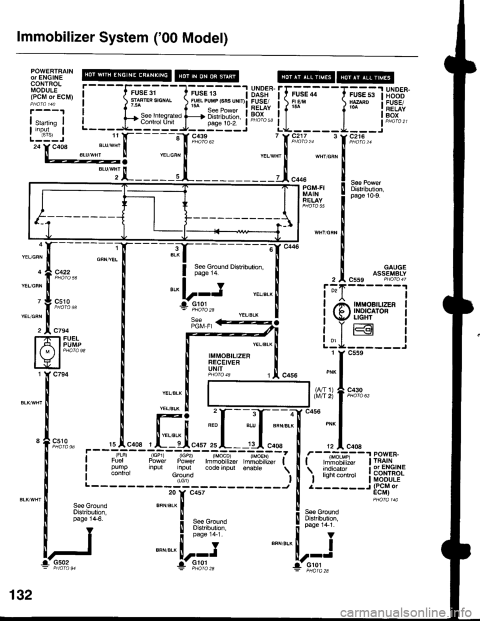
lmmobilizer System ('00 Model)
POWERTRAINol ENGINECONTROL;,6ri iriE' !- - - - -F^-E; -
I 1,'r._,..--:
-'j
!.i3!.* i f ;.-. *-
- -
F ;; ; I H 3BB"(Pclvl or EcM) I ( rri-*." ",ono. rua ruur lsns urrll Firser i o_e,n xrano I FUsEi
ig-r i fl^.ee,ntesra,ed fi;rl,u,:l i iEioi i f
"'-
l
'*"
iEEf'
! :"'ll,l' ! L---g-_'ry_+J-:_E.:gil
"u'*
il.^=---=I-= -i;;eo'�'
io"-r, I B:i,fffil
!4.1ry.. : pase lo-e.RELAY
WHI/GRN
;{---------61'c446 t
i ;;6;;;uno o'"u'u"'on l I GAuGE
""i;i ,.""..1
i*':,:""#'= PHoro2s
| ! (9 ilSi'"ito" I
yffi
i"Yffi i
| ,""o",.,r.*
-'-=--l t;ia;;----'
I "ffi;f:'- ,.!, "ouu ""- I
"..".* i I
I I l"#fl;llF#'*"
, ffi ".,, ILF"l'�
"."
; I "..,
7;:F,
-;:*+
,-�Tr,u-,"*"tilt, f I [-;*tn-
-l
isx,fi^'no"
ul.:ii'o codeinput enabre
I iilfli:lT*, itf$Egf(LGr)-J | 2------J (PCM or20
tr,
c4s7
| :,"#,.,enr erx | ! s." crouna
t g"-:,Bn'*,l l
guW
"""".-U:i' BFN""l--i
i:-f,:g:,, Yffi:
".,"":r------*-";T
^
| ,"!::.," !
-:":fr'*,,
I
[f,"i;. I
".--rr
l N
'lr**"" ,,tr*,
I
i--!r,
*.**il
iltlw
IJ: PHafag4
132