bulb HONDA INTEGRA 1998 4.G Owner's Guide
[x] Cancel search | Manufacturer: HONDA, Model Year: 1998, Model line: INTEGRA, Model: HONDA INTEGRA 1998 4.GPages: 1681, PDF Size: 54.22 MB
Page 1270 of 1681
J
)
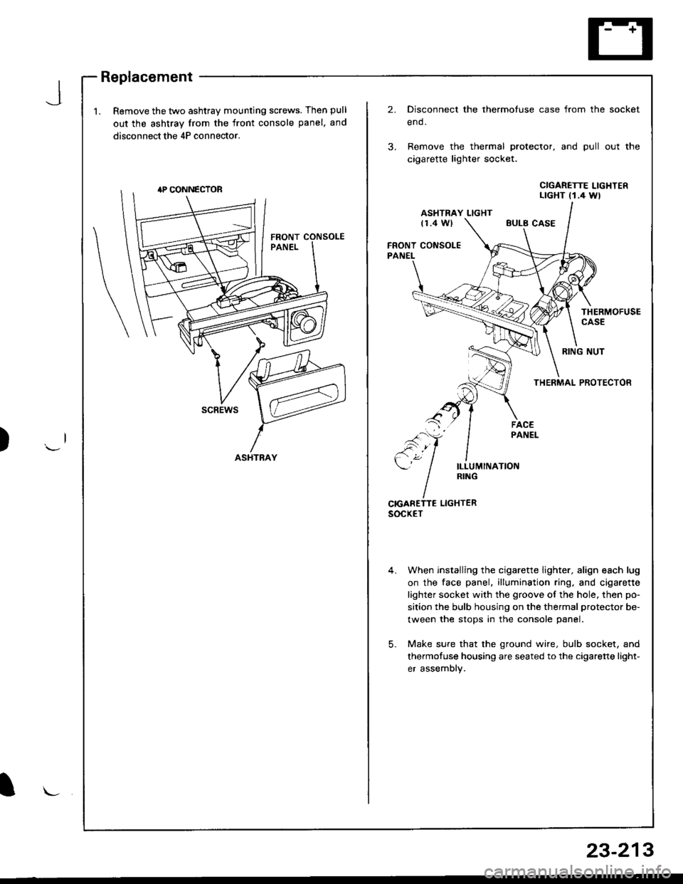
1.Remove the two ashtray mounting screws. Then pull
out the ashtray from the front console panel. and
disconnect the 4P connector.
2.Disconnect the thermofuse case from the
end.
Remove the thermal protector, and pull
cigarette lighter socket.
socket
out the
CIGARETTE LIGHTERLTGHT t1.4 Wl
ASHTRAY LIGHTt1.4 WlEULB CASE
FRONT CONSOLEPANEL
THERMOFUSECASE
RING NUT
THERMAL PROTECTOR
scREws
ILLUMINATIONRING
CrcANETTE LIGHTERsocxET
When installing the cigarette lighter, align each lug
on the face panel, illumination ring, and cigarette
lighter socket with the groove of the hole. then po-
sition the bulb housing on the thermal protector be-
tween the stops in the console panel.
Make sure that the ground wire, bulb socket, and
thermofuse housing are seated to the cigarette light-
er assembly.
5.
ASHTRAY
l\-
23-213
Page 1274 of 1681
)
Switch Removal
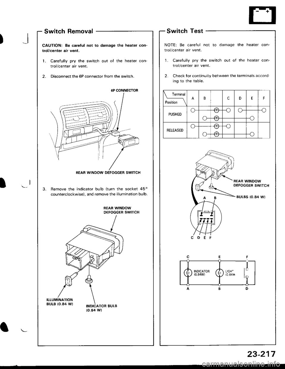
CAUTION: Be carelul not to damage the heater con-
trol/center air vent.
1. Carefully pry the switch out oI the heater con-
trol/center air vent.
2. Disconnect the 6P connector from the switch.
Remove the indicator bulb (turn the socket 45o
counterclockwise), and remove the illumination bulb.
REAR WINDOWDEFOGGER SWITCH
INDICATOR BULB(o.84 W)
.l
Switch Test
NOTE: Be careful not to damage the heater con-
trol/center air vent.
'1. Carefully pry the switch out of the heater con-
trol/center air vent.
2. Check tor continuity between the terminals accord
ing to the table.
Terminal
pLN-_\BcDEF
PUSHEDo/:\-oo--o
o-
\:./
-o\:/
RELEASEDo-/:\_o
-oo-
\:,/
/:\\:./
I
6P CONNECTOR
REAR WINDOW DEFOGGER SWITCH
23-217
Page 1308 of 1681
Cruise Control
)
Component LocationIndex
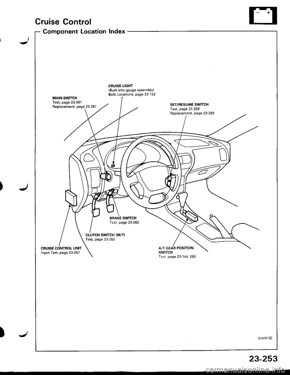
CRUISE LIGHT{Built into gauge assembly)Bulb Locations, page 23 122MAIN SWITCHTest, page 23-261Replacement, page 23-261SET/RESUME SWITCHTest, page 23 259Feplacement, page 23'259
BRAKE SwlTCHTest, page 23-262
CLUICH SWITCH IM/T)Test, page 23 262
cRutsEA/T GEAR POSITIONswtTcHTest, page 23-144,263Input Test, page 23 257
(cont'd)
23-253
Page 1313 of 1681
Cruise Control
- Control Unit InputTest(cont'dl
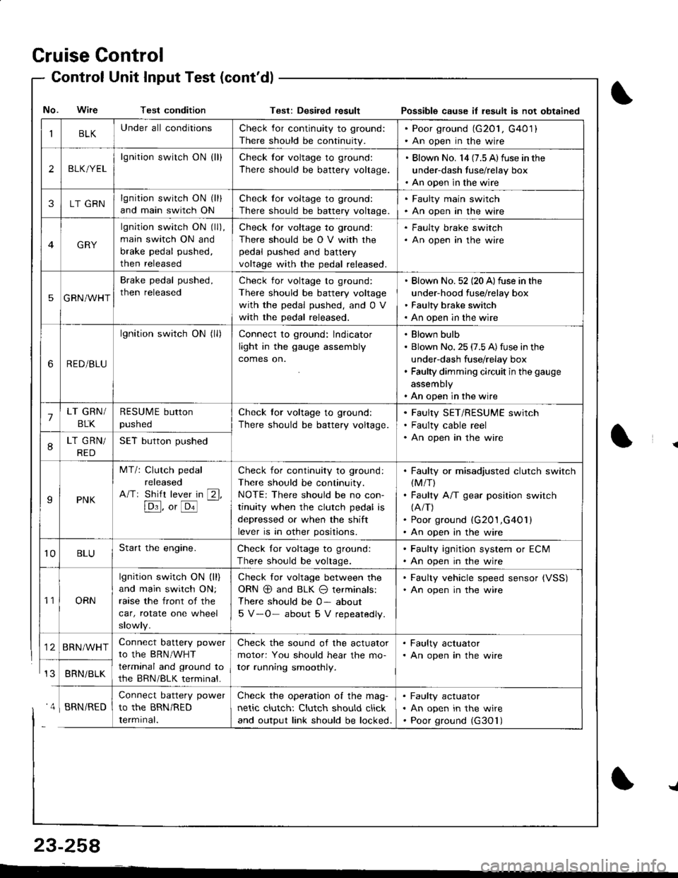
IBLKUnder all conditionsCheck for continuity to ground:
There should be continuity.
. Poor ground (G20l, G401). An open in the wire
2BLK/YEL
lgnition switch ON {ll}Check for voltage to ground:
There should be battery voltage.
. Blown No. l4 (7.5 Alfuse in the
under-dash fuse/relay box. An open in the wire
3LT GRNlgnition switch ON (ll)
and main switch ON
Check for voltage to ground:
There should be battery voltage.
. Faulty main swjtch. An open in the wire
GRY
lgnition switch ON (ll),
main switch ON and
brake pedal pushed,
then released
Check for voltage to ground:
There should be O V with the
pedal pushed and battery
voltage with the pedal released.
. Faulty brake switch. An open in the wire
5GRN/WHT
Brake pedal pushed,
then released
Check for voltage to ground:
There should be battery voltage
with the pedal pushed, and 0 V
with the pedal released.
Blown No. 52 (20 A)fuse in the
under-hood fuse/relay box
Faulty brake switch
An open in the wire
6RED/BLU
lgnition switch ON (ll)Connect to ground: lndicator
light in the gauge assembly
comes on.
Blown bulb
Blown No. 25 (7.5 A)fuse in the
under-dash fuse/relay box
Faulty dimming circuit in the gauge
assembly
An open in the wire
7LT GRN/
BLK
RESUME button
pushed
Check tor voltage to ground:
There should be battery voltage.
Faulty SET/RESUME switch
Faulty cable reel
An open in the wire8LT GRN/
RED
SET button pushed
IPNK
MT/: Clutch pedal
released
A/Tr Shift lever in [2l,
[Dl]. o, [o'l
-
Check for continuity to ground:
There should be continuity.
NOTE: There should be no con-
tinuity when the clutch pedal is
depressed or when the shift
lever is in other positions.
Faulty or misadjusted clutch switch(M/T)
Faulty A/T gear position switch(A/T)
Poor ground (G201,G401)
An open in the wire
't0BLUStart the engine.Check lor voltage to ground:
There should be voltage.
. Faulty ignition system or ECM. An open in the wire
't1ORN
lgnition switch ON (ll)
and main switch ON;
raase the front of the
car, rotate one wheel
slowly.
Check for voltage between the
ORN @ and BLK O terminals:
There should be 0- about
5 V-O- about 5 V repeatedly.
. Faulty vehicle speed sensor {VSS). An open in the wire
BRN/WHTConnect battery power
to the BRN/WHT
terminal and ground to
the BRN/BLK terminal.
Check the sound of the actuator
motor: You should hear the mo-
tor running smoothly.
. Faulty actuator. An open in the wire
BRNi BLK
Connect battery power
to the BRN/RED
Iermrnal.
Check the operation of the mag-
netic clutch: Clutch should click
and output link should be locked.
Faulty actuator
An open in the wire
Poor ground (G30'l)
No. Wire Test conditionTest: Desiled result Possible cause il lesult is not obtained
' 4 I BRN/RED
{
{
23-258
-L
Page 1347 of 1681
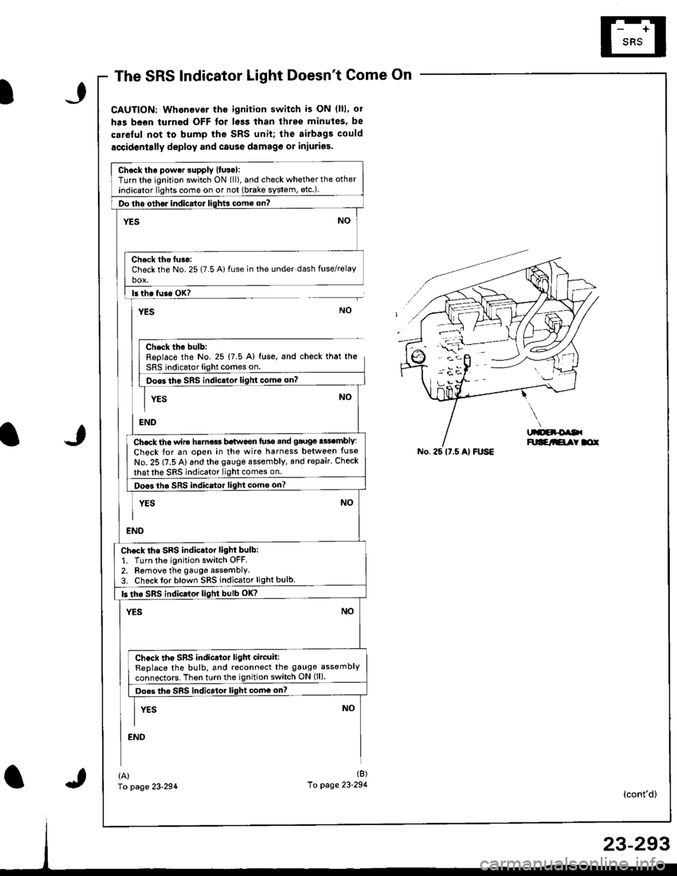
The SRS Indicator Light Doesnt Come On
CAUTION: Whenever the ignition switch is ON (lll, ol
has been turned OFF tor lsss than three minutes. be
careful not to bump the SRS unit; the airbags could
accidentslly deploy and cause damage or iniuries.
Chcck tho power supply lfuso):Turn the ignition switch ON (ll), and check whether the other
indicator lights come on or not (brake system, etc.).
Do tho oth6J indicator ligh$ come on?
NO'ES
Check ths tuse:Check the No. 25 (7.5 Ai fuse in the under dash fuse/relayho!
ls th. tu.o OK?
YESNO
Chsck the bulb:Replace the No. 25 17.5 A) fuse, and check that the
SRS indicator light comes on.
Doos tho SRS indic.lor light como on?
YES
END
Ch.ck th6 wir€ ham€ls b€twoen fu3e snd gauge .3sembly:
Check for an open in the wire harness belween tuse
No. 25 (7.5 A) and the gauge sssembly, and repair. Check
that the sRS indicator light comes on.
Doo3 the SRS indicator light come on?
YES
NO
NO
END
Ch6ck tho SRS indicator light bulb:
1. Turn the ignition switch OFF.2. Remove the gauge assemblY3. Check tor blown SRS indicator light bulb.
b tho sRs indicrlor light bulb oK?
YESNO
Check tho SRS indicator ligln circuit:ReDlace the bulb, and reconnect the gauge assembly
connectors. Then turn the ignition switch ON (ll).
Do.s tho SRS indicrtor light comG on?
I vrs NoII
END
No. 25 lt.5 Al FUSE
{A)fo page 23-294
(B)
10 page 23-294(cont'd)
Page 1394 of 1681
'l'
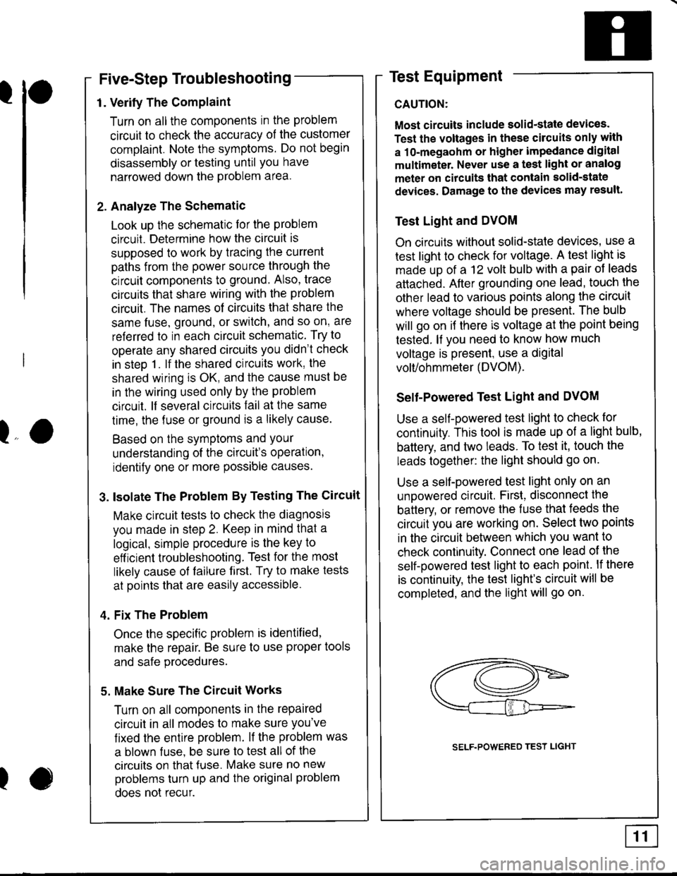
Five-Step Troubleshooting
1. Verify The Complaint
Turn on all the components in the problem
circuit to check the accuracy of the customer
complaint. Note the symptoms. Do not begin
disassembly or testing until you have
narrowed down the Problem area.
2. Analyze The Schematic
Look up the schematlc for the problem
circuit. Determine how the circuit is
supposed to work by tracing the current
paths from the power source through the
circuit components to ground. Also, trace
circuits that share wiring with the problem
circuit. The names of circuits that share the
same fuse, ground, or switch, and so on' are
referred to in each circuit schematic. Try to
operate any shared circuits you didn't check
in steo 1. lf the shared circuits work, the
shared wiring is OK, and the cause must be
in the wiring used only by the problem
circuit. lf several circuits fail at the same
time, the fuse or ground is a likely cause.
Based on the symptoms and Your
understanding of the circuit's operation,
identify one or more possible causes.
3. lsolate The Problem By Testing The Circuit
Make circuit tests to check the diagnosis
you made in step 2. Keep in mind that a
logical, simple procedure is the key to
eff icient troubleshooting. Test for the most
likely cause of failure f irst. Try to make tests
at points that are easily accessible.
4. Fix The Problem
Once the specific problem is identified,
make the repair. Be sure to use proper tools
and safe procedures.
5. Make Sure The Circuit Works
Turn on all components in the repaired
circuit in all modes to make sure you've
fixed the entife problem. lf the problem was
a blown f use, be sure to test all of the
circuits on that {use. Make sure no new
problems turn up and the original problem
does not recur.
Test Equipment
CAUTION:
Most circuits include solid-state devices.
Test the voltages in these circuits only with
a 1o-megaohm or higher impedance digital
multimeter. Never use a test light or analog
meter on citcuits that contain solid-state
devices. Damage to the devices may result.
Test Light and DVOM
On circuits without solid-state devices, use a
test light to check for voltage. A test light is
made up of a 12 volt bulb with a pair of leads
attached. After grounding one lead, touch the
other lead to various points along the circuit
where voltage should be present. The bulb
will go on i{ there is voltage at the point being
tested. lf you need to know how much
voltage is present, use a digital
volVohmmeter (DVOM).
Selt-Powered Test Light and DVOM
Use a self-powered test light to check for
continuity. This tool is made up of a light bulb,
battery, and two leads. To test it, touch the
leads together: the light should go on.
Use a self-powered test light only on an
unoowered circuit. First, disconnect the
battery, or remove the fuse that feeds the
circuit you are working on. Select two points
in the circuit between which you want to
check continuity. Connect one lead ol the
self-powered test light to each point. lf there
is continuity, the test light's circuit will be
completed, and the light will go on.
lo
I
SELF.POWERED TEST LIGHT
Page 1489 of 1681
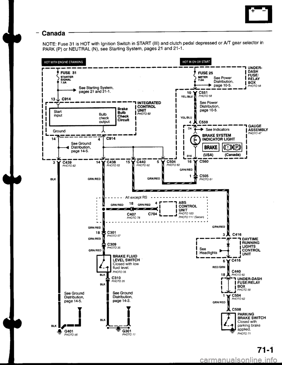
- Canada
NOTE: Fuse 3l is HOT with lgnition Switch in START (lll) and clutch pedal depressed or A/T gear selector in
PARK (P) or NEUTRAL (N), see Starting System, pages 21 and 21-1.
;;;----
----l;";;-----l
iiSF:'
:'eI[^ ) fg'" see Power | lEiiv
^ seesiarrins sysrem, --- j'[ffi-- j #"1""------'+ pig6 Zr a;d 2r-r. !- - To-v cssr
i r- 3li:Tf8l r---r--_l
| | y tBRAKEil((lJ)(EDt I
L - -r4 - - - - - - - r- - - - - J. - - - - -l - i L= J- g'j'- - S3g1-,
.[Hr*. "IF#1s,, ''f,"c,flls. 'It*'t"i_[
^.^.
*- I o^n".' | | o"n".o L___:;[ s;*,,
lri:
tl
I :-I------ Arrexcept Rs -----------: t
I ii%d#i__jflffi: i I
| """;l
'- ll
I * Vg,l.gl,,
o'""'1.!.
"o'u
i-----f
-1Ri-[iil,'"
I
*"ff;i;-.,.,,"
LEb'r.ji_jb'f,{H*
I l#[i.#rsr
"-"fX;;;;.,
| ].1s*" [Tr P.ls.',ePfiv
|
**1
Lljti';-! see Ground ! See Grouno
'-,oij---------=-*"-,,;---J
i i Anmg"#l''3;' i-
-
l--ffi'Pilr"r-l t ' iiYffi@i
--I -i:"-:-- J-----L---I -i L= J-rs'i-- r"=sr.i
i it"!,8li6l i iq,iit"l :'fl"";'#.,
i
**'?
i
**''; *""*i:;;-
l!."1 IrflBAt['JS*,""
l--J
*^L---l
|y', I Shtrl'l-"
itooo, '---& [+! iPPtreo.: PHoTa s6 PHofall - PHora 71
: | - - --'l uauuc
crourd l ! i t *lA se€ Indicators lfr1s-eyerv
BulbcnecKoutpur
71-1
Page 1491 of 1681
- How the Circuit Works
The low engine oil pressure indicator light works in
two ways: il flashes continuously following a
momentary loss of engine oil pressure, or it comes
on and stays on with a complete loss of engine oil
oressure,
When the engine first starts, before its oil pressure
rises above 4.3 psi, voltage is applied to the closed
and grounded engine oil pressure switch and the
light comes on to test the bulb.
With the engine running, voltage is applied at the
WHT/BLU wire of the integrated control unit. With
normal engine oil pressure, the engine oil pressure
switch is open and the low oil pressure indicator
light does not come on. lf the engine oil pressure
switch closes momentarily (more than 0.5 seconds)
but then opens again, the YEURED wire at the
integrated control unit will sense ground through the
switch. The integrated control unit will then provide
and remove ground for the low oil pressure indicator
light through the YEURED wire. The light will flash
on and off until you turn the ignition switch off. The
flashing feature will not work until 30 seconds after
initial voltage is applied to the WHT/BLU wire of the
oil pressure indrcator llasher circuit. This delay
keeps the low oil pressure indicator light from
coming on during engine warm-up.
lf engine oil pressure falls below 4.3 psi and does
not increase, the engine oil pressure switch will stay
closed. The low oil pressure indicator light will then
come on and stay on.
Refer to the Service Manual (Section 23, Electrical)
for specific tests or troubleshooting procedures.
72-1
Page 1502 of 1681
How the Circuit Works
The maintenance reminder light comes on to
remind the driver that the car is due for
scheduled mainlenance.
The maintenance reminder unit receives a vehicle
speed input from the vehicle speed sensor (VSS)
and uses this inlormation to compute the distance
traveled. For the first 6000 t 1 00 miles (9650 t 160
km) after the maintenance reminder light is reset, it
will come on for two seconds when you turn the
ignition switch to ON (ll) as a bulb check.
Between 6000 1 100 miles (9650 t 160 km) and
7500 t 100 miles (12070 I 160 km) the reminder
light will come on for two seconds when you turn
the ignition switch to ON (ll), and then flash for eight
seconds more.
Beyond 7500 t 100 miles (12070 t l60 km) the
reminder light will stay on when the ignition switch is
in the ON (ll) position until the unit is reset.
To reset the unit, the car must be parked and the
ignition switch in the ON (ll) position. Press the
reset button on the unit and hold it there for more
than three seconds, and the reminder light will
go off.
Refer to the Service Manual (Section 23, Electrical)
for specific tests or troubleshooting procedures.
83-1
Page 1504 of 1681
- How the Circuit Works
With the ignition switch in ON (ll) or START (lll),
voltage is applied to the A,/T gear position indicator.
The A,/T gear position switch provides a ground for
each position. As an input is grounded, ils indicator
light comes on. lf you se,ecl B, tor example, ground
will be applied to the input of the A,/T gear position
indicator, and the R indicator bulb will come on.
With the headlight switch in PARK or HEAD, voltage
is applied to the RED/BLK wire terminal. this
changes the indicator panel illumination from lixed
to controlled by the dash lights dimmer inpul
through the RED wire.
When the lransmission ('98.�99 models) or
powertrain ('00 model) control module (TCM or
PCM) detects an abnormality in the automatic
transmission control system, or when you request
diagnostic trouble codes through the service
check connector, the TCM or PCM will make lhe D4
indicator light blink.
Refer to the Service Manual (Section 14,
Automatic Transmission) for soecific tests or
troubleshooting procedures.
89-1