HONDA INTEGRA 1998 4.G Service Manual
INTEGRA 1998 4.G
HONDA
HONDA
https://www.carmanualsonline.info/img/13/6069/w960_6069-0.png
HONDA INTEGRA 1998 4.G Service Manual
Trending: low beam, clock, mirror controls, light, cruise control, ESP, charging
Page 41 of 1681
L
o)
II
a
c
c
'6
E
G
z
i
=
c
F
c
z
6
(J
.z
.9
!!$
za
'6o
oo-:' q)
Y]
'i:
,)o :-
'ti '6! 7
:!-: (o
.;:>E O
OY EIYo.t
Eo9? g 6'-a o .:
:b :t u
;: i 39X --- ob; ii .Esir ; E
.eI X :oo x ;sa = c:e F c
.:l ; :':.:.:qi X.y.i.i6=!1'a9 .!:o!; E c 6 PYi= - o!:
Ez oo9:!
4': EU; l:
h! F*;eF- : g<) - a.=(E !a ^cD o c .1.= E F -! o*oE !9.9.!:s B 99 -9, R€ ".
6,! ..i; i'q3
;EeiEiiEO- .:PPE;P
sd; !i:E*::-=tf,! c= oqquJFo
u !.9 ;.....
z9oltg ETcirrBPPJ
F
z
E
E
E
g
.9
'a
I
.9
:E
9=
6,;q,o6a)o,€
*E
,; .q5.ito* EE6':
s93
Ei3
3!3;
--!::
.i; F
I P*;E;
c:E3;=6;!xd'5
999
ooo
I
Et
e;€gEt
H€g
a:P
3a--
=*;
-ei E
!!:
iEi
:6;
3:?9:]
i E+o Ez
5a
98
Y,9
Gg
€s
TE,
nE
+9
!,t >E(!
!i!
-E€3
E
.9
aa
c.i
€
e
a
]
!E
a
o
oao
ooa
oaa
aao
oaa
oaa
aao
I
6
p! 6
:i 9F
E
.zo
ao
.g
E
€
@
;
.9
€!
;OE
d+ I
4-7
Page 42 of 1681
ra
Engine
Engine Removal/lnstallation ............. 5-1
Cylinder Head/Valve Train ............... 6-1
Engine Block ......... ........7-1
Engine Lubrication .........8-1
Intake Manifold/Exhaust System ...... 9-1
Cooling ....... 10-1
Page 43 of 1681
\-a
Engine Removal/lnstallation
Speciaf Tools .......... ...........5-2
Engine RemovaUlnstallation ................ 5-3
Mount/Bracket Torque .... 5-17
)
Page 44 of 1681
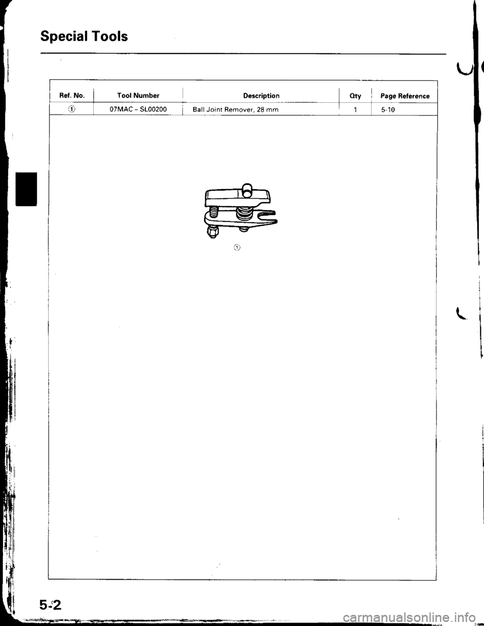
Special Tools
Rel. No. I Tool NumberDescriptionOty I Page Reterence
o07MAC - SL00200 Ball Joint Remover, 28 mm,l5 10
L
Page 45 of 1681
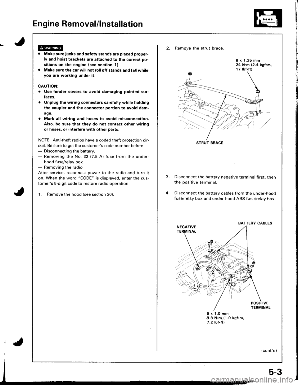
Engine Removal/lnstallation
2. Remove the strut brace.
Make sure iacks and safety stands ate placed plopel-
ly and hoist brackets are attached to the correct po-
sitions on the engine {see section 11,
Make sure the car will not rollolt stands and latl whileyou are wgrking under it.
8 x 1.25 mm24 N.m {2.4 kgf.m,17 tbf.tt)
CAUTION:
. Use fender covers to avoid damaging painted sur-
faces.
Unplug the wiring connectors carelully while holding
the coupler and the connector portion to avoid d8m-
age.
Mark all wiring and hoses to avoid misconnection.
Also. be sure that they do not contact other wiring
or hoses, or intedere with other parts.
NOTE: Anti-theft radios have a coded theft protection cir-
cuit. Be sure to get the customer's code number betore- Disconnecting the battery.- Removing the No.32 (7.5 A) fuse from the under
hood fuse/relay box.
Removing the radio
After service, reconnect power to the radio and turn it
on. When the word "CODE" is displayed, enter the cus
tomer's 5-digit code to restore radio operation.
1. Remove the hood (see section 20).
3.Disconnect the battery negative terminal first, then
the positive terminal.
Disconnect the battery cables Irom the under-hood
Iuse/relay box and under hood ABS {use/relay box.
6x1.0mm9.8 N.'4 (1 .0 kgf .m,
7.2 rbf.ft)
(cont'dl
STRUT BRACE
BAITERY CABLES
5-3
Page 46 of 1681
En gine Remova l/l nstal lation
(cont'dl
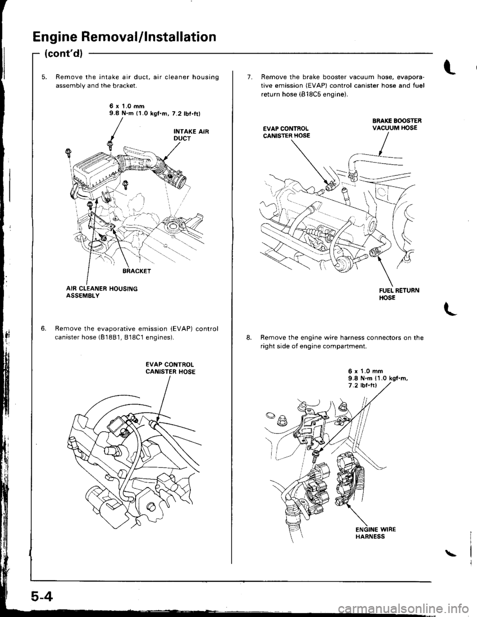
Remove the intake air duct, air cleaner housing
assembly and the bracket.
6 r 't.0 mm9.8 N.m (1.0 kgt.m, 7.2 lbf.ft)
Remove the evaporative emission {EVAP)
canister hose (B 18B1, B'18C1 eng;nes).
control
5-4
\
7. Remove the brake booster vacuum hose, evapora-
tive emission (EVAP) control canister hose and tuel
return hose (818C5 engine).
Remove the engine wire harness connectors on the
right side of engine compartment.
6 x 1.0 mm9.8 N.m l1.O kgl.m,
Page 47 of 1681
Page 48 of 1681
Engine Ramoval/lnstallation
(cont'dl
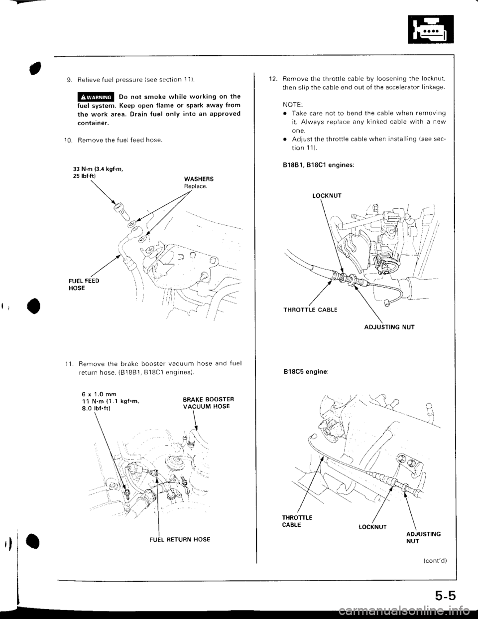
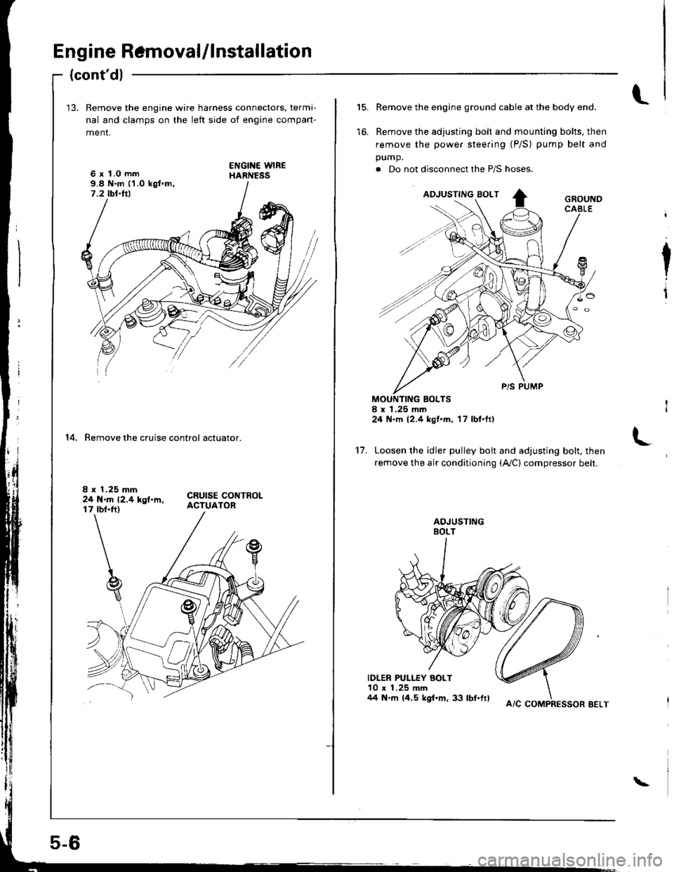
13. Remove the engine wire harness connectors, termi-
nal and clamps on the left side ot engine compan-
menr,
6 x 1.0 mm9.8 N.m 11.0 kgl.m,7.2 tbt.ttl
14. Remove the cruise control actuator.
I x 1.25 mm24 N.m 12.4 kgt.m,17 tbt.ft)
5-6
A/C COMPRESSOR EELT
\
l.15.
to.
Remove the engine ground cable at the body end.
Remove the adjusting bolt and mounting bolts, then
remove the power steering (P/S) pump belt and
pump.
. Do not disconnect the P/S hoses.
MOUNTING BOLTSI x 1.25 mm24 N.m 12.4 kgt'm, 17 lbl.ft)
Loosen the idler pulley bolt and adjusting bolt, then
remove the air conditioning (Ay'C) compressor belt.
IDLER PULLEY BOLT10 x 1.25 mm/14 N'm 14.5 kgf.m, 33 lbt'frl
I
I
't7.
Page 49 of 1681
Page 50 of 1681
Engine Removal/lnstallation
(cont'd)
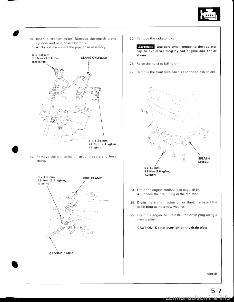
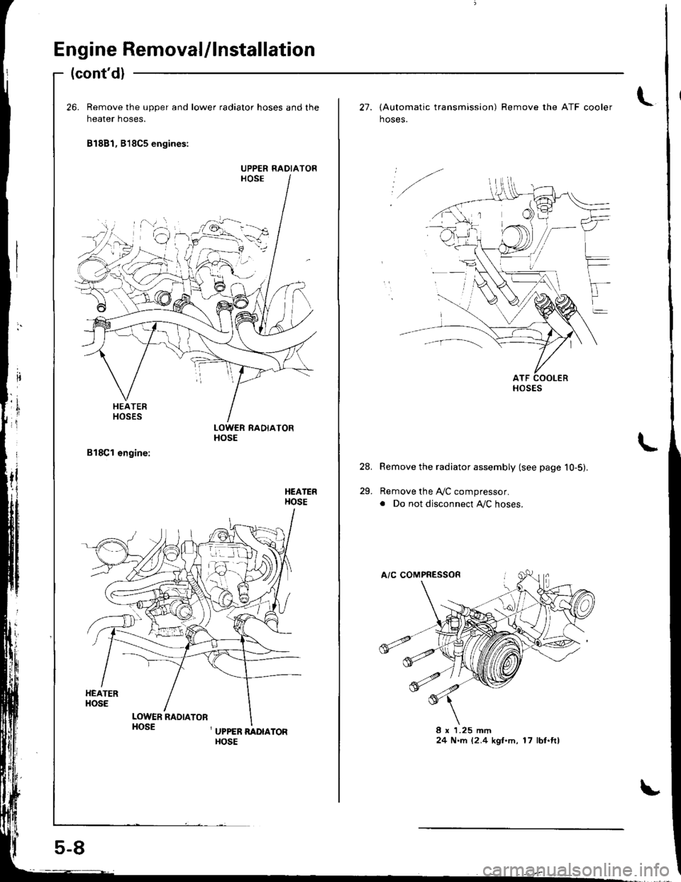
26. Remove the upper and lower radiator hoses and the
heater hoses.
81881, B18C5 engines:
LOWCR RADIATORHOSE
HEATERHOSE
HEATERHOSE
LOWER RADIATORHOSE, UPPER RADIAToRHOSE
UPPER RADIATOR
,1
ir
..f.
c
5-8
t27. lAutomatic transmission) Remove the ATF cooler
hoses.
Remove the radiator assembly (see page 10-5).
Remove the A,/C compressor.
. Do not disconnect Ay'C hoses.
8 x 1.25 mm24 N.rn 12.4 kgl.m, 17 lbf.ft)
24.
29.
HOSES
Trending: fuse box, fuse box diagram, manual radio set, lock, relay, automatic transmission fluid, four wheel drive
![HONDA INTEGRA 1998 4.G Service Manual L
o)
II
a
c
c
6
E
G
z
i
=
c
F
c
z
6
(J
.z
.9
!!$
za
6o
oo-: q)
Y]
i:
,)o :-
ti 6! 7
:!-: (o
.;:>E O
OY EIYo.t
Eo9? g 6-a o .:
:b :t u
;: i 39X --- ob; ii .Esir ; E
.eI X :oo x ;sa = c:e F c
.:l HONDA INTEGRA 1998 4.G Service Manual L
o)
II
a
c
c
6
E
G
z
i
=
c
F
c
z
6
(J
.z
.9
!!$
za
6o
oo-: q)
Y]
i:
,)o :-
ti 6! 7
:!-: (o
.;:>E O
OY EIYo.t
Eo9? g 6-a o .:
:b :t u
;: i 39X --- ob; ii .Esir ; E
.eI X :oo x ;sa = c:e F c
.:l](/img/13/6069/w960_6069-40.png)


