fuse HONDA INTEGRA 1998 4.G Service Manual
[x] Cancel search | Manufacturer: HONDA, Model Year: 1998, Model line: INTEGRA, Model: HONDA INTEGRA 1998 4.GPages: 1681, PDF Size: 54.22 MB
Page 1000 of 1681
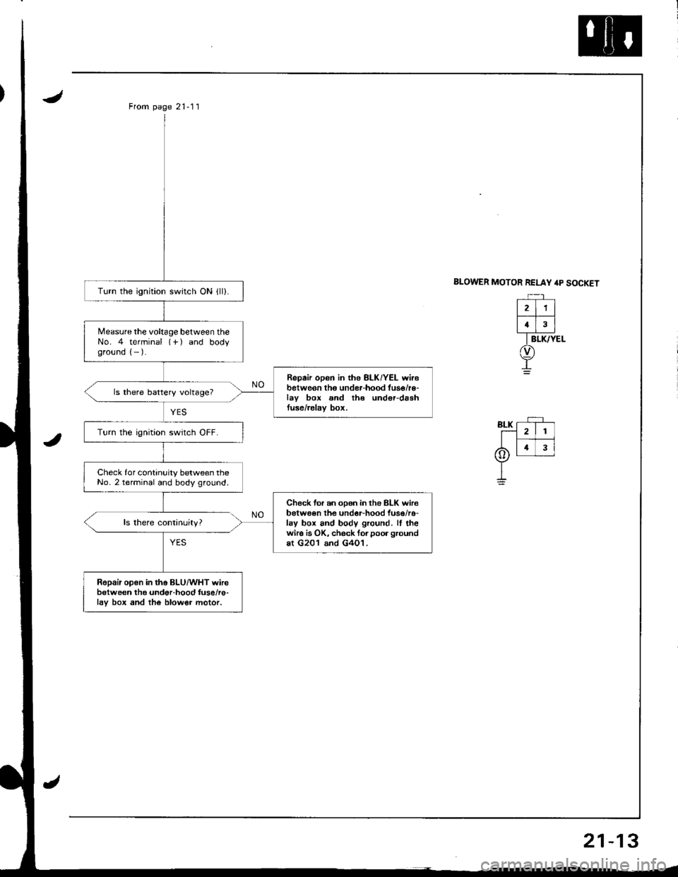
From page 21-11
BLOWER MOTOR RELAY /rp SOCKETTurn the ignition switch ON {ll).
Measure the voltage between theNo. 4 terminal (-f ) and bodyground (- ).
Repair open in the BLK/YEL wirebetweon tho under-hood tuse/r€-lav box and th€ und€r-drshtuse/relav box.
ls there battery voltage?
Turn the ignition swrtch OFF.
Check for continuity between theNo. 2 terminal and body ground.
Check for an oDen in the BLK wir€belween the undor-hood fuso/re-lay box and body ground. It thewire is OK, check forpoor groundat G201 and G4O1.
Ropair open in the BLU/WHT wirebetween the undor-hood fuse/re-lav box and the blow€r motor.
21
4
Page 1001 of 1681
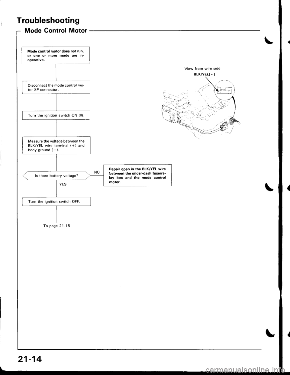
Troubleshooting
Mode Control Motor
Mode controlmotor does nol run.or ong or more mode are in-operatve.
Disconnect the mode control mo-tor 8P connector.
Turn the ignrtion switch ON (ll).
Measurethe voltage between theBLK/YEL wire terminal {+ ) andbody ground (- ).
Repair open in ths BLK/YEL wirebetween the und€r-dash fusehe-lay box and the mods cont.olmotoa,
Turn the ignition swirch OFF.
ls there battery voltage?
To page 21 15
21-14
Page 1024 of 1681
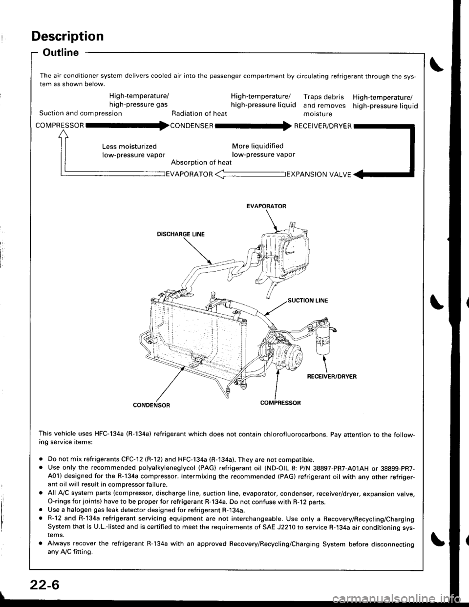
Description
Outline
The air conditioner system delivers cooled air into the passenger companment by circulating retrigerant through the sys-
tem as shown below.
High-temperature/ H ig h-tem peratu rel Traps debris High-temperature/high-pressure gas high-pressure liquid and removes high-pressure liquidSuction and compression Radiation of heat moisture
covpnEsson -tl4con oetsen -rr{ REcEIvER/DRvER
More liqu idified
low-pressure vapor
Absorption of heat
Less moisturized
low-pressure vapor
EVAPORATOR -TEXPANS|ON VALVE
EVAPORATOR
CONDENSOR
This vehicle uses HFC-134a (R-134a) refrigerant which does not contain chlorofluorocarbons. Pay attention to the follow-ing service items:
. Do not mix refrigerants CFC-12 (R-12) and HFC-134a (R-134a). They are not compatible.. Use only the recommended polyalkyleneglycol (PAG) refrigerant oil (ND-OIL 8: P/N 38897-PR7-A01AH or 38899-PR7-A01) designed for the R-134a compressor. Intermixing the recommended (PAG) refrigerant oil with any other refriger-ant oil will result in compressor failure.
. All AVC system parts (compressor, discharge line, suction line. evaporator, condenser, receiver/dryer, expansion valve.O-rings for joints) have to be proper for refrigerant R-134a. Do not confuse with R-12 parts.
. Use a halogen gas leak detector designed for refrigerant R-134a.. R-12 and R-134a refrigerant servicing equipment are not interchangeable. Use only a Recovery/Recycling/ChargingSystem that is U.L.-listed and is certified to meet the requirements of SAE J2210 to service R-134a air conditioning sys-tems.
. Always recover the refrigerant R-134a with an approved Recovery/Recycling/Charging System before disconnectingany Ay'C fitting.
22-6
Page 1025 of 1681
J
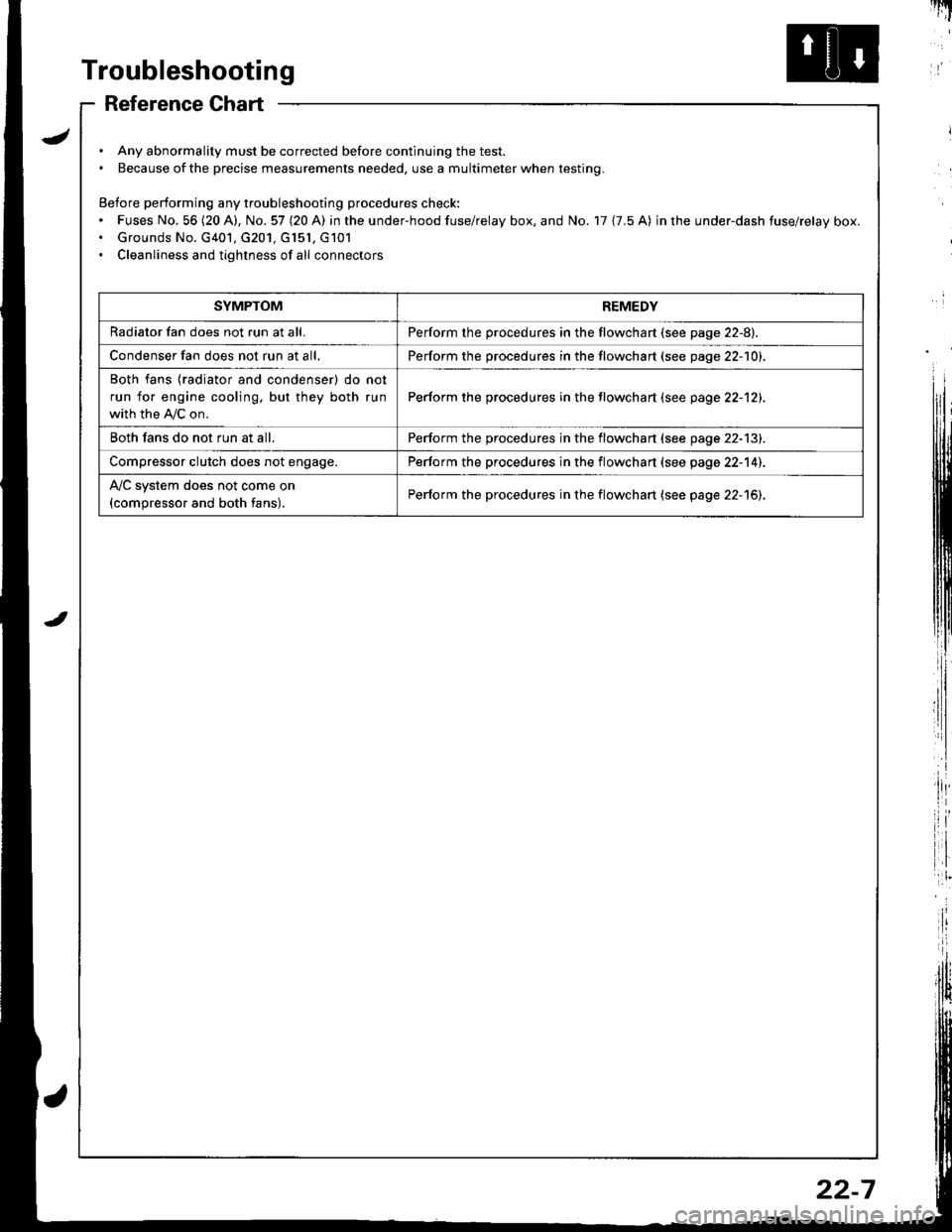
Troubleshooting
Reference Chart
. Any abnormality must be corrected before continuing the test.. Because of the precise measurements needed, use a multimeter when testing.
Before performing any troubleshooting procedures check:. Fuses No, 56 (20 A), No. 57 (20 A) in the under-hood fuse/relay box, and No. 17 {7.5 A) in rhe under-dash fuse/relay box.. Grounds No. G401, G201, G151, G101. Cleanliness and tightness of all connectors
I'IT
I
I
SYMPTOMREMEDY
Radiator fan does not run at all.Perform the procedures in the flowchart {see page 22-8).
Condenser fan does not run at all,Perform the procedures in the flowchart (see page 22-1O1.
Both fans {radiator and condenser) do not
run for engine cooling, but they both run
with the IVC on.
Perform the procedures in the tlowchart (see page 22-12).
Both fans do not run at all.Perform the procedures in the flowchart (see page 22-13).
Compressor clutch does not engage.Perform the procedures in the flowchart (see page 22-14).
l'lc system does not come on
{compressor and both fans).Perform the procedures in the flowchart (see page 22-15).
22-7
Page 1026 of 1681
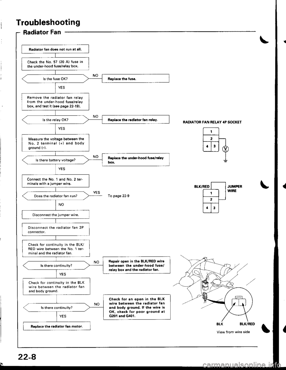
Troubleshooting
Radiator Fan
RADIATOR FAN RELAY 4P SOCKET
El2F-lt--T-- |
ujj I
I
",-*rrro [--l .u^rrrr
E lw'RE
l2-
trI
\
\
8LK BLK/RED
View from wire side\
Radiator lan does not run at all.
Chock the No. 57 (20 A) fuse in
the undeFhood fuse/relay box.
Remove the radiator tan relayfrom the under-hood fuse/rolaybox, and test it (see page 22-19).
Measuro the voltag€ betwogn theNo.2 terminal (+) and bodyground (-).
ls there battery voltage?
Connect the No. 1 and No. 2 ter-minals with a jumper wire.
Does the radiator fan run?
Check for continuity in the BLK/RED wire between the No. 1 ter-minal and the radiator fan.
Repair open in tho BLK/RED wir6b6twaon the undor-hood fuso/r6l6v box and the radirtorf6n.ls there continuity?
Check Ior continuity in the BLKwire between the radiator lanand body ground.
Chock for.n opon in tho BLKwiro botween tho .adiator fanand body ground, It tho wire i3OK, check for poor ground rtG201 and G401.
ls there continuity?
Roolace the radiator tan motor.
10 page 22-9
22-8
Page 1028 of 1681
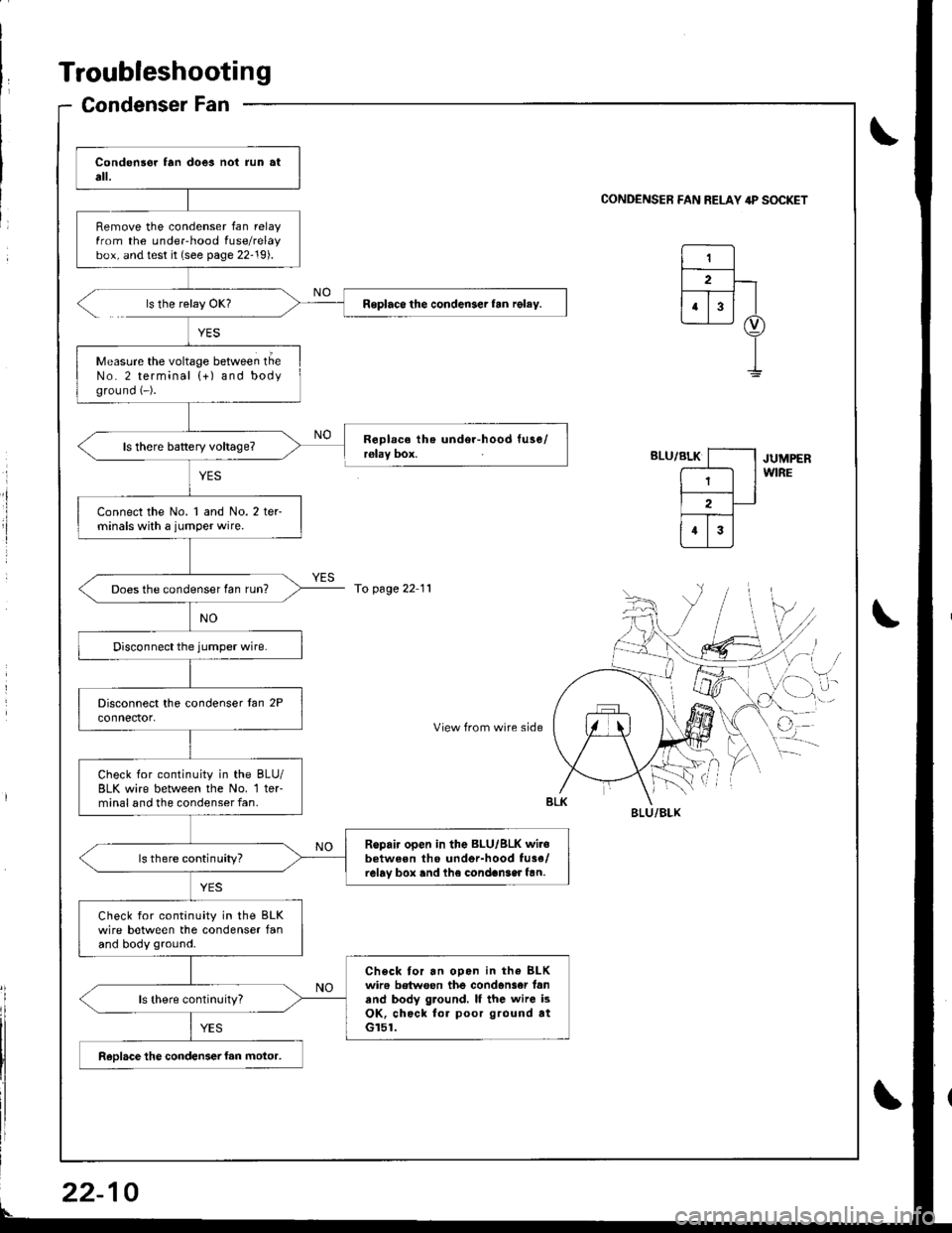
Troubleshooting
Condenser Fan
0
Remove the condenser fan relayfrom the underhood fuse/relaybox, and test it (see page 22-19).
Roplaco the condenser fan rgley.
Measure the voltage between tlieNo. 2 terminal {+) and bodyground (-).
Connect the No. 1 and No. 2 ter-minals with a jumper wire.
Does the condenser fan run?
Check for continuity in the BLU/BLK wire between lhe No. 1 ter'minal and the condenser fan.
Ropair open in the BLU/BLK wir.between tho undor-hood fu3e/relay box and lh€ condan3er fan.ls there continuity?
Check for continuity in the BLKwire between the condenser fanand body ground.
Check tor an ooen in the BLKwir6 betwoen the condan3er fanand body ground. lf the wire isOK, check for poor ground atGr51.
ReDlace the condenser fan motor,
CONDENSER FAN RELAY 4P S(rcKET
ls the relay OK?
YES
RoDlace the undor-hood tuse/r€lay box.JUMPERWIRE
To page 22 11
',,/-i, /
cr-i,
View from wire sideq
BI-U/BLX
22-
Page 1031 of 1681
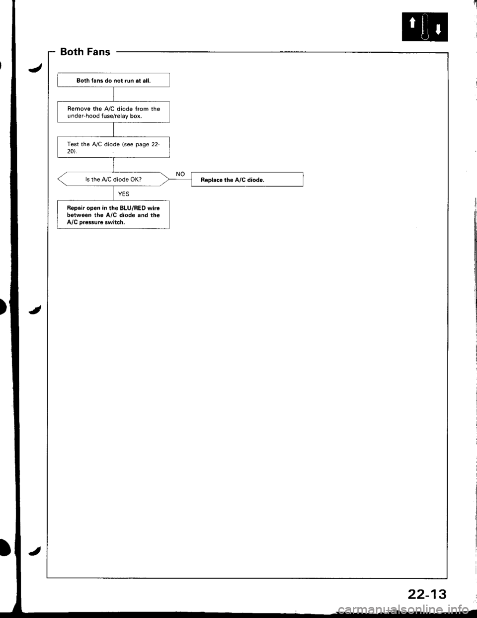
BothFans
)
Eoth lans do not run et all.
Removo the A,/C diode from theunder-hood fuse/relay box.
ls the IVC diode OK?
Repeir open in the BLU/RED wirebetween the A/C diode and theA/C Dr€ssure swhch.
22-13
Page 1060 of 1681
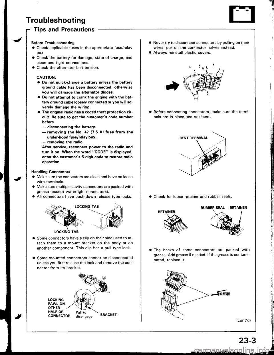
Troubleshooting
Tips and Precautions
Never try to disconnect connectors by pulling on their
wires; pull on lhe connector halves instead.
Alwavs reinstall Dlastic covers.
Before connecting connectors, make sure the termi-
nals are in Dlace and not bent.
a Check lor loose retainer and rubber seals.
The backs of some connectors are packed with
grease. Add grease if needed. lf the grease is contami-
nated, reolace it.
(cont'd )
RETAINER
K
Bef ore Troubleshooting
a Check applicable tuses in the appropriate fuse/relay
box.
Check the battery for damage, state of charge, and
clean and tight connections.
Check the alternator belt tension.
CAUTION:
a Do not quick-charge a battely unless the battery
ground cable has been disconnected. otherwise
you will damage the alternator diod€s.
a Do not attempt to crank the engine with the bat-
tery ground cable loosely connected or you willse-
verely damage the wiring.
a The originsl radio has a coded theft plotection cir-
cuit. Be sure to get the customel's code numbel
before- disconnecting the battsry.- removing the No. 47 (7.5 A) fuse from tho
under-hood luse/relay box.- removing the radio.
Atter service. leconnect Dower to the radio and
tum it on. When the word "CODE" is displayed,
enter the customer's 5-digit code to restore radio
ooeration.
Handling Connectors
a Make sure the connectors are clean and have no loose
wire terminals.
a Make sure multiple cavity connectors are packed with
grease (except watertight connectors).
a All connectors have push-down release type locks.
LOCKING TAB
LOCKING TAB
Some connectors have a clip on their side used to at-
tach them to a mount bracket on the body or on
another component. This clip has a pull type lock.
Some mounted connectors cannot be disconnected
unless you tirst release the lock and remove the con-
nector from its bracket.
LOCKINGPAWL ONOTHERHALF OFCONNECTORPull todisengageBRACKET
Page 1062 of 1681
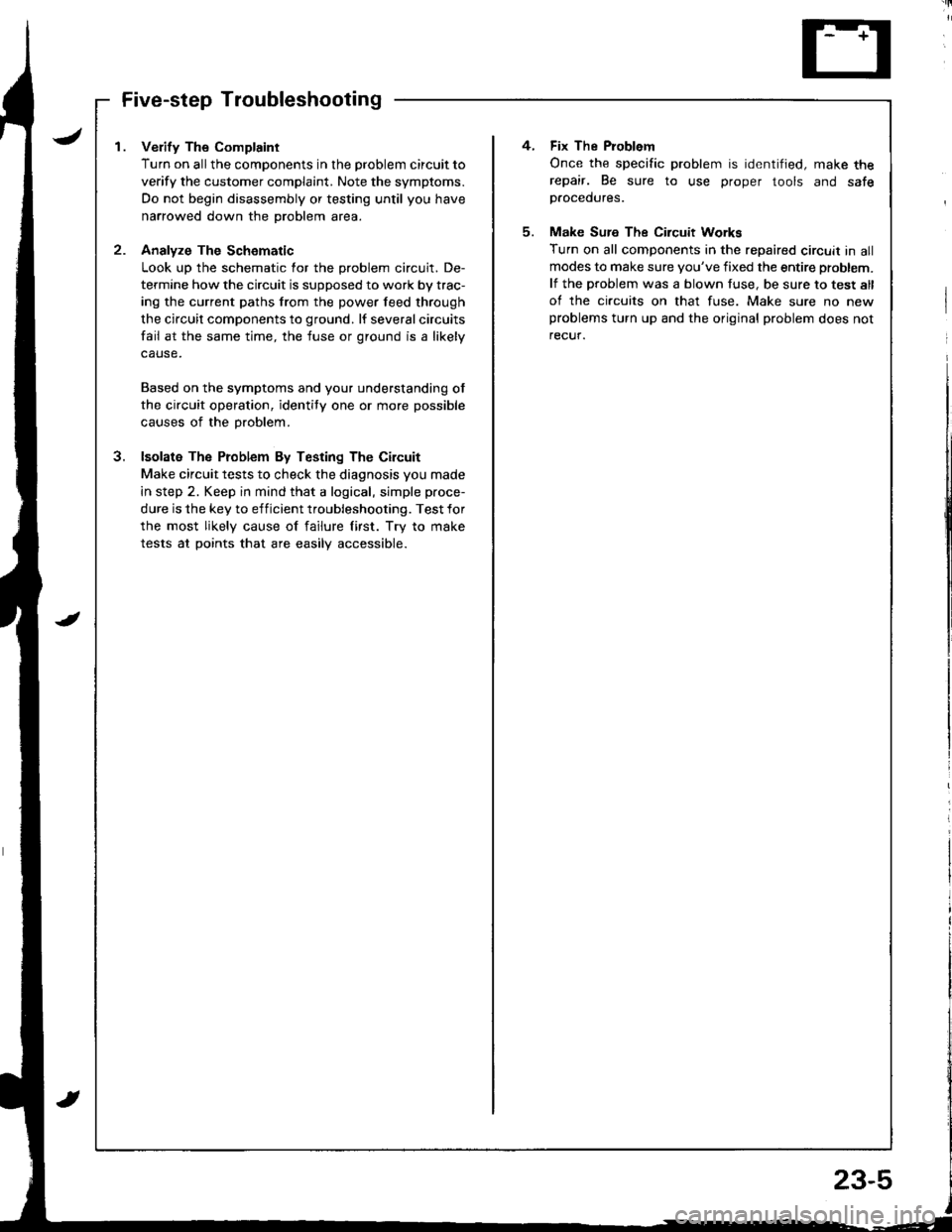
I . Verify The Complaint
Turn on allthe components in the problem circuit to
verify the customer complaint. Note the symptoms.
Do not begin disassembly or testing until you have
narrowed down the problem area.
2- Analyze The Schomatic
Look up the schematic for the problem circuit. De-
termine how the circuit is supposed to work by trac-
ing the current paths from the power feed through
the circuit components to ground. lf several circuits
fail at the same time, the fuse or ground is a likely
Based on the symptoms and your understanding ot
the circuit operation, identity one or more possible
causes of the problem.
3. lsolata The Problem By Testing The Circuit
Make circuit tests to check the diagnosis you made
in step 2. Keep in mind that a logical, simple proce-
dure is the key to efficient troubleshooting. Test for
the most likely cause of failure lirst. Try to make
tests at points that are easilV accessible.
4. Fix The Problem
Once the specific problem is identified, make therepair. Be sure to use proper tools and safep.ocedures.
5. Make Sure The Circuit Workg
Turn on all components in the repaired circuit in allmodes to make sure you've fixed the entire problem.
lf the problem was a blown fuse, be sure to test all
of the circuits on that fuse. Make sure no newproblems turn up and the original problem does not
recuf.
Page 1063 of 1681
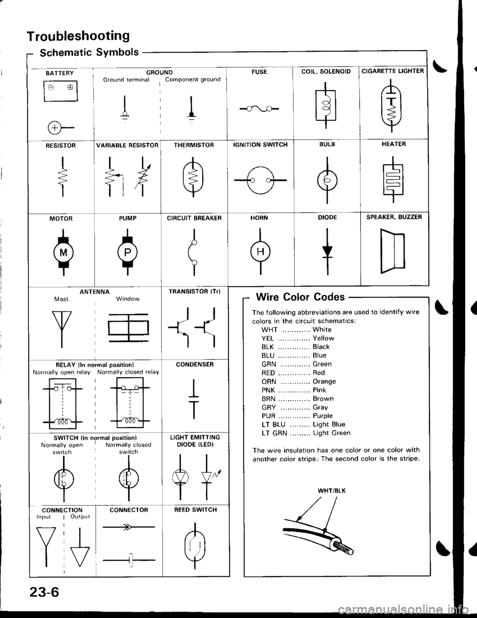
Troubleshooting
Schematic Symbolsym
BATTEBY
tr3
o-
GROUNDGround terminal Componenr ground
I il
FUSE
rhtdl
l9l.|
CIGARETTE LIGHTER
,A
lrl
Y
RESISTOR
+
T
VARIABLE RESISTOR
TD
=rX
ttf
THERMISTOR
/b'
t=l
v
IGNITION SWITCH
1-\-T- l.--
BULB
A
Y
HEATER
-h
t=l
tr
MOTOR
0
PUMP
A
Y
CIRCUIT EREAKER
I
t
Y
HORN
+
DIODE
+
SPEAKER, BUZZER
D
Mast
Y
ANTtiNNA
T,
TRANSISTOR (Tr)
ll
+1^'l
)
Wire Color Codes
The following abbreviations are used to identify wire
colors in the circuit schematics:
WHT ............ White
YE1 .............. Yellow
81K .............. Black
B1U .............. Blue
GRN ............. Green
RED .............. Red
ORN ............. Orange
PNK .............. Pink
BRN .............. Brown
GRY ............. Gray
PUR .............. Purple
LT BLU ......... Light Blue
LT GRN ......... Light Green
The wire insulation has one color or one color with
another color stripe.'The second color is the stripe.
WHT/BLK
,//,aI,//t- /
R
BELAY lln noNormally open relayrmal position)
Normally closed relay
-tr-f,-
l=T= |
til
trf
CONDENSER
I
T
SWITCH {ln nrNormally openswitch
I
/6\
v
I
)rmal position)Normally closed
I
A
w
I
LIGHT EMITTINGDIODE (LEDI
AJ"
YT
CONNE
V
I
CTIONOutput
J,
CONNECTOR
+>-
l-l'l
REED SWITCH
.K
Irr ]
Y