fuse HONDA INTEGRA 1998 4.G Owner's Manual
[x] Cancel search | Manufacturer: HONDA, Model Year: 1998, Model line: INTEGRA, Model: HONDA INTEGRA 1998 4.GPages: 1681, PDF Size: 54.22 MB
Page 472 of 1681
u.drrf,,
J
J
J
14-55
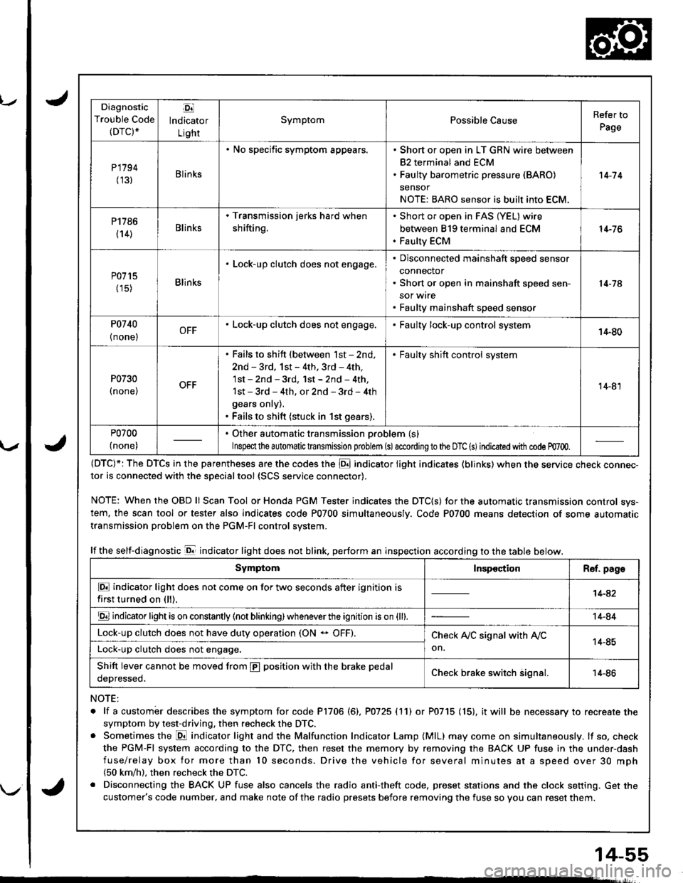
Diagnostic
Trouble Code(DTC).
Ej
lndicator
Light
SymptomPossible CauseRefer to
Page
P1794
(131Blinks
. No specific symptom appears.. Short or open in LT GRN wire between
82 terminal and ECM. Faulty barometric pressure (BARO)
sensor
NOTE: BARO sensor is built into ECM.
't 4-7 4
P1786
(14)Blinks
. Transmission jerks hard when
shifting.
Short or open in FAS (YEL) wire
between 819 terminal and ECM
Faulty ECM
14-76
P0715
(15)Blinks
. Lock-up clutch does not engage,Disconnected mainshaft speed sensor
connector
Short or open in mainshaft speed sen-
sor wrre
Faulty mainshaft speed senso.
14-74
P0740
{ none,OFF. Lock-up clutch does not engage.Faulty lock-up control system14-80
P0730
I none,
. Fails to shift (between lst - 2nd,
2nd - 3rd, 1st - 4th. 3rd - 4th,
1st - 2nd - 3rd, 1st - 2nd - 4th,
1st - 3rd - 4th, or 2nd - 3rd - 4th
gears onry).. Fails to shift (stuck in 1st gears).
. Faulty shift control system
14-81
P0700
(none)
. Other automatic transmission problem (s)
Inspeclthe a utomatic transmission problem (s)accordingto the DTC (s)indicated with code m700.
(DTC)*: The DTCS in the parentheses are the codes the E indicator light indicates (blinks) when the service cnecK connec-tor is connected with the sDecialtool {SCS service connector).
NOTE: WhentheOBDll Scan Tool orHonda PGM Tester indicates the DTC(S) for the automatic transmission control sys-
tem, the scan tool or tester also indicates code P0700 simultaneously. Code P0700 means detection of some automatic
transmission problem on the PGM-Fl control system.
lf the self-diagnostic E indicator light does not blink. perform an inspection according to the table below.
NOTE:
. lf a custombr describes the symptom for code P1706 (6), P0725 (11) or P0715 (15), it will be necessary to recreate the
symptom by test-driving, then recheck the DTC,. Sometimes the E indicator light and the Malfunction Indicator Lamp (MlL) may come on simultaneously. lf so, check
the PGM-Fl system according to the DTC, then reset the memory by removing the BACK UP fuse in the under-dash
fuse/relay box for more than l0 seconds. Drive the vehicle for several minutes at a speed over 30 mph(50 km/h). then recheck the DTC.
. Disconnecting the BACK UP fuse also cancels the radio anti-theft code, preset stations and the clock setting. Get the
customer's code number, and make note of the radio presets before removing the fuse so you can reset them.
SymptomInspectionR€f. page
E indicator light does not come on for two seconds after ignition is
first turned on (ll).14-42
E indicator light is on constantly (not blinking) wheneverthe ignition is on {ll).14-84
Lock-up clutch does not have duty operation (ON - OFF).Check A,/C signal with Ay'C
on.14-85Lock-up clutch does not engage.
Shift lever cannot be moved from E position with the brake pedal
oeDresseo.Check brake switch signal.14-86
Page 497 of 1681
Electrical Troubleshootin g
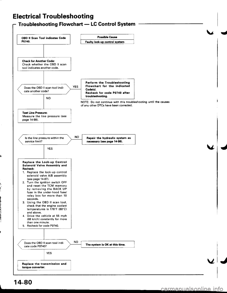
Troubleshooting Flowchart - LC Control System
\.r.Poeribl. C.ua.
control
NOTE: Do not continue with this troubleshootingot any other DTCS have beeo corrected.until thg caus€s
v
t,
I
'I
14-80
Chock lor Anothor Cod6:Check whether the OBD lltool indicates another codo.
P6rform tha TroublorhootingFlowcha for tho indicrladCodolsl.R.ch.ck fof codo P0740 !ft.tt.oublo3hooting.
Does the OBD ll scan tool indi-cate another code?
Tost Line Proisurg:Measure the line pressure (see
pag6 14-98).
R.prir tho hydraulic syltcm !!n.cGsary (soc pago 1+98).ls the line prsssure within theservic€ limit?
Repl!c6 th6 Lock-up ControlSolenoid Velva As3ambly .ndRschock:1. Replace the lock-up controlsolenoid valve y'y'B assembly(see page '!4-87).
2. Turn the ignition switch OFFand reset the TCM memoryby removing the BACK UPfuse in the und€r-hood fuse/rolay box tor more than 10seconos.3. Using the OBD ll scan tool,check that the engine coolanttemperatures is 176'F (80'C)
4. Drive the vehicle at 55 mph(88 km/h) constantly lor rnorethan one mrnute,5. Recheck for code P0740.
Does the OBD ll scan tool indi-cate codo P0740?Tha iy3t6m ir OK .t thi! timc.
V
I
J
Page 498 of 1681
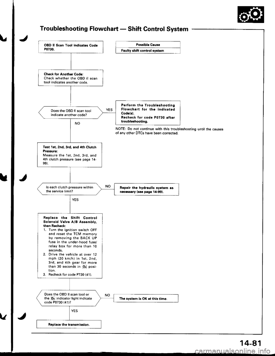
Troubleshooting Flowchart - Shaft Control System
NOTE: Do not continue with this troubleshootlng until the causesof any other DTCS have been corrected.
Chock foi Another Code:Check whether the OBD ll scantool indicates another code.
Psrtorm tho Tioubla3hootingFlowch.rt fo. th. indicatodCodcl.l.Rechsck tor code P0730 attoltroublolhooting.
Does the OBD ll scan toolindicate anothor code?
Tost 1st, 2nd, 3rd, and 4th ClutchProssuro:Measure the 1st,2nd,3rd, and4th clutch pressure (see page 14-
ls each clutch pressure withinthe service limit?R.p!ir lhG hydraulic ry3t.m ranac.3!.ry l3€e pago 1+991.
Roplace the Shilt ContiolSolonoid Valve A/B Assombly,thon Recheck:1. Turn the ignition switch OFFand reset the TCM memoryby removing the BACK UPfuse in the under-hood fuse/relay box for more than '10
seconds.2. Orive the vehicle at over 12mph (20 km/h) in lst,2nd,3rd, and 4th gear for morethan 30 seconds in E posi-tion.3, Recheck for code P730 (41).
Does the OBD llscan toolorthe E indicator light indicatecode P0730 (4'1)?Tho systom is OX etthi3 timo.
Poitible C.uBe
F""lty "hlft ".^t..t ",/"t".
Page 650 of 1681
Steering
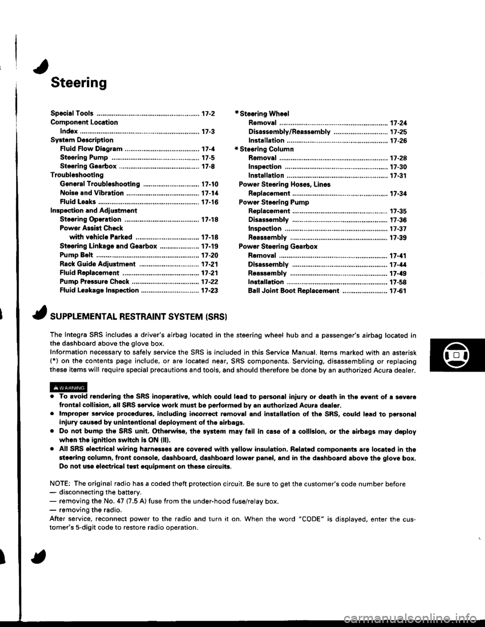
Componsnt Location
lndox
*Stooring Wheel
Removal ....
Disassombly/Ro8$.mbly
Disassombly ......
F08$€mbly
Powcr Stosring Gosrbox
R6moval
............................ 17-3
............. 17 -1
................ 17-16
............................. 17_25
17-30
17.31
.......17-21
Sy3tom DGcription
Fluid Flow Disgram
Steering Pump .............. 17-5
Stocring Goarbox ...17.8
Troublorhooting
Gonoral Troubleshooting .............................. 17.10
Noiso lnd Vibration ...... 17-1i[
Fluid Losk3
lnspoction
Installation
Powor Steering Hos6, Lino3
Roplacom€nt .................. 17.34
Powor Steoring Pump
RGplac6montlolpeqtion lnd Adiu3tm6nl
Stoo.ing Operation
Powor A$bi Chock
with v.hiclo Parked
Stcering Linkage 6nd Goarbox
Pump Bolt
17.18
17.18
17.19
17-20
17.35
t7-36
17 -37
r7-39
Inspoction
................... 17.41
Rack Guide Adiustmont ..........................-.-.-. 17 -21
Ffuid Rcplacemont ........17-21
Pump Prc&suro Chock ...,........................,..,..., 17 -22
Fluid Leakage Inrpection ............................... 17-23
Dissssembly
R€aEs€mbly
In3tallation........... 17_58
Ball Joint Boot Replacem.ni ........................ 17-61
17-U
17.49
J ,urrar*TNTAL REsrRArNr sysrEM (sRsr
The Integra SRS includes a driver's airbag located in the steering wheel hub and a passenger's airbag located inthe dashboard above the glove box,
Information necessary to safely service the SRS is included in this Service Manual. ltems marked with an asterisk(*) on the contents page include, or are located near, SRS components. Servicing, dissssembling or replacing
these items will require special pr6cautions and tools, and should therefore be done by an authorized Acura dealer.
. To avoid rondoring ths SRS inoparstivo. which could |rad to parsonal iniury or doath in the ov€nt of ! sev6.o
trontal collision, all SRS sarvice work must be perto.med by an authorizod Acura dsalor.. lmpropor 3orvic€ procadures, including inco[6ql rgmoval and inrtallation of the SRS, could l6ad to pgrsonal
iniury clus€d by unintentional doployment of the airbags,. Do nol bump tho SRS unh, (Xherwise, th6 3ystom may fail in cas€ ol a collision, or the airbags may d€ploy
when ths ignition switch is ON {ll).. All SRS electrical wiring harness€s aro covered with yallow insulation. Related component3 are located in ths
stcaring column. tront con3ol6, dashboard, d.shbolrd lower panel, and in the dashboard above ths glove box.
Do not u3o electrical test oquipm€nt on the3e circuii3.
NOTE: The original radio has a coded theft protection circuit. Be sure to get the customer's code number before- disconn€cting the battery.- removing the No. 47 (7.5 A) fuse from the under-hood fuse/relay box,- removing the radio.
After service, reconnect power to the radio and turn it on. When the word "CODE" is displayed. enter the cus-
tomer's 5-digit code to restore radio operation.
Page 678 of 1681
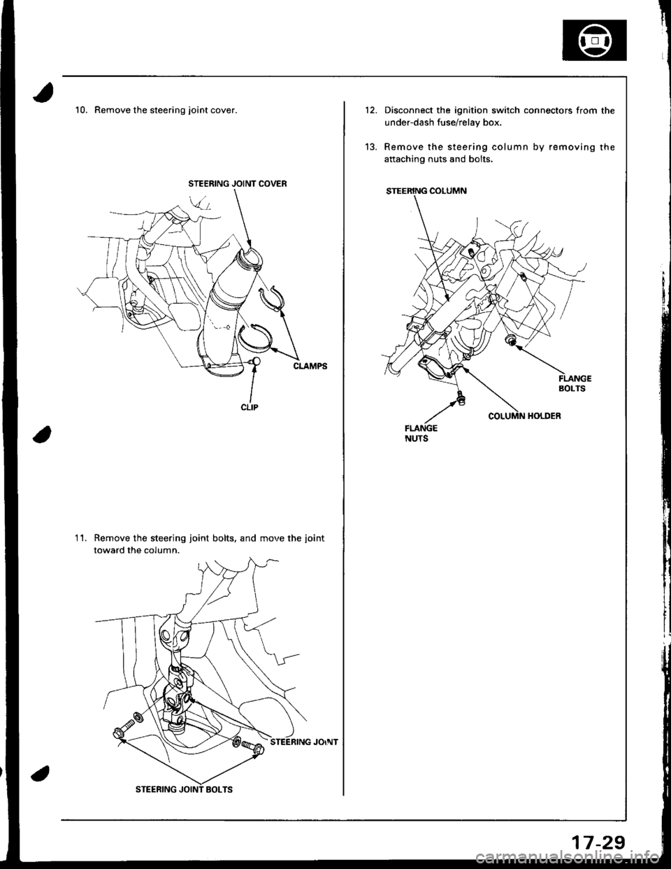
10. Remove the steering joint cover.
Remove the steering joint bolts, and move the iointtoward the column.
11.
JOINT COVER
12.
'13.
Disconnect the ignition switch connectors from the
under-dash fuse/relay box.
Remove the steering column by removing the
aftaching nuts and bolts.
17-29
Page 682 of 1681
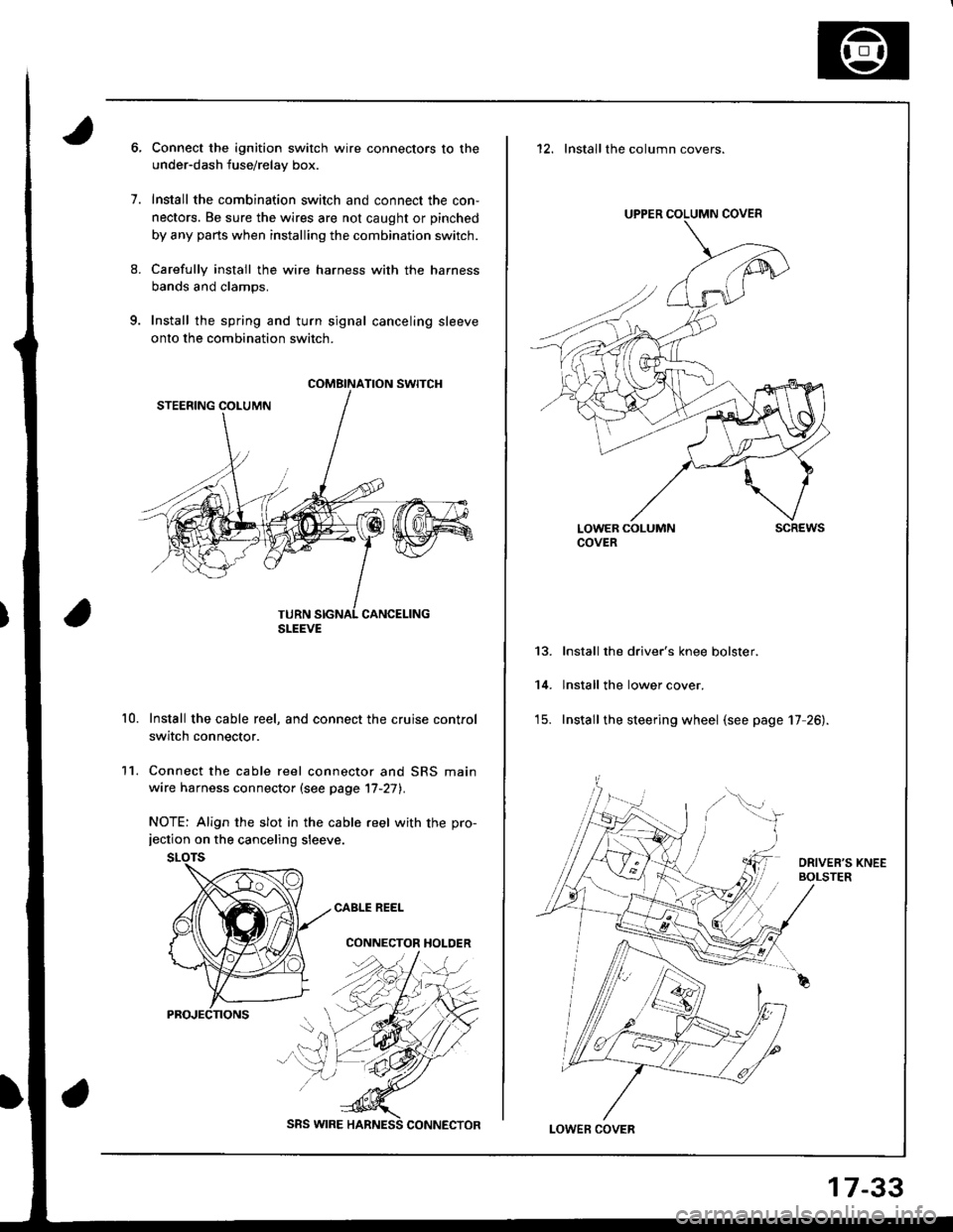
9.
1.
8.
11.
10.
Connect the ignition switch wire connectors to the
under-dash fuse/relay box.
Install the combination switch and connect the con,
nectors. Be sure the wires are not caught or pinched
by any parts when installing the combination switch.
Carefully install the wire harness with the harness
bands and clamps.
Install the spring and turn signal canceling sleeve
onto the combination switch.
Install the cable reel, and connect the cruise control
switch connector.
Connect the cable reel connector and SRS main
wire harness connector (see page '17-27).
NOTE: Align the slot in the cable reel with the pro-jection on the canceling sleeve.
CABLE REEL
CONNECTOR HOLDER
COMBINATION SWITCH
SLEEVE
SRS WIRE
17-33
12. Installthe column covers.
UPPER COLUMN COVER
LOWER COLUMNCOVERscREws
13.
14.
Install the driver's knee bolster.
lnstall the lower cover.
Install the steering wheel (see page 17 26).
LOWEF COVER
Page 777 of 1681
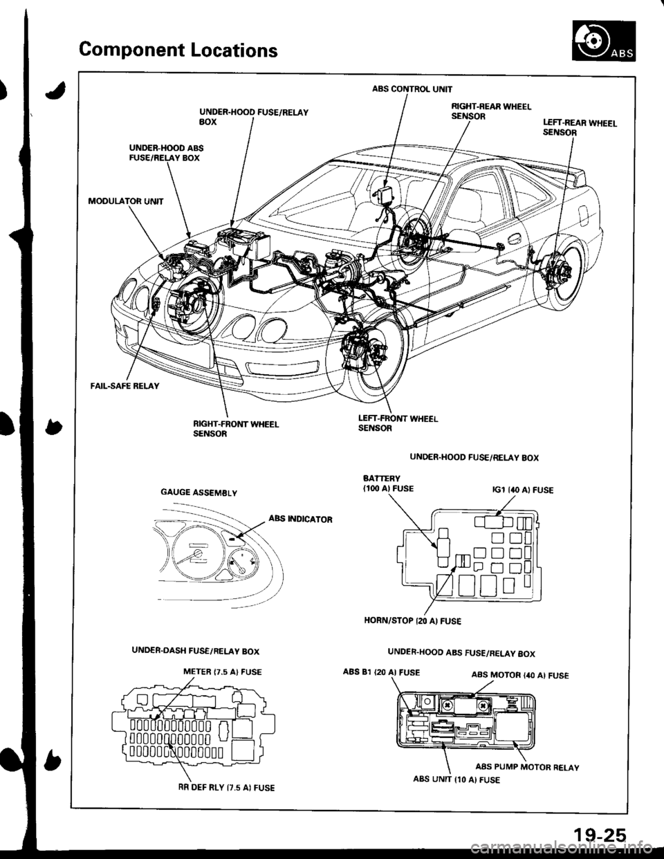
Gomponent Locations
,)
ABS CONTROL UNIT
UNDER.HOOD FUSE/RELAYRGHT-NEAR WHEELsEillioRaoxLEFT.REAR WHEEI-SENSOR
UNDER-H(X)D ABS
MODULATOR UNIT
FAIL-SAFE RELAY
RIGHT-FRONT WHEELSENSOR
LEFT-FROl{T WHEELSENSOR
UNDER.HOOD FUSE/RELAY BOX
ABS INDICATOR
UNDER.HOOD ABS FUSE/RELAY 8OX
ABS 81 {20 AI FUSEAAS MOTOR {40 Al FUS€
AAS PUMP MOTOR RELAY
GAUGE ASSEMBLY
!D
Dtrt]
HORN/STOP I2O A) FUSE
A8S UNIT {10 AI FUSERR DEF FI-Y I7.5 AI FUSE
19-25
Page 782 of 1681
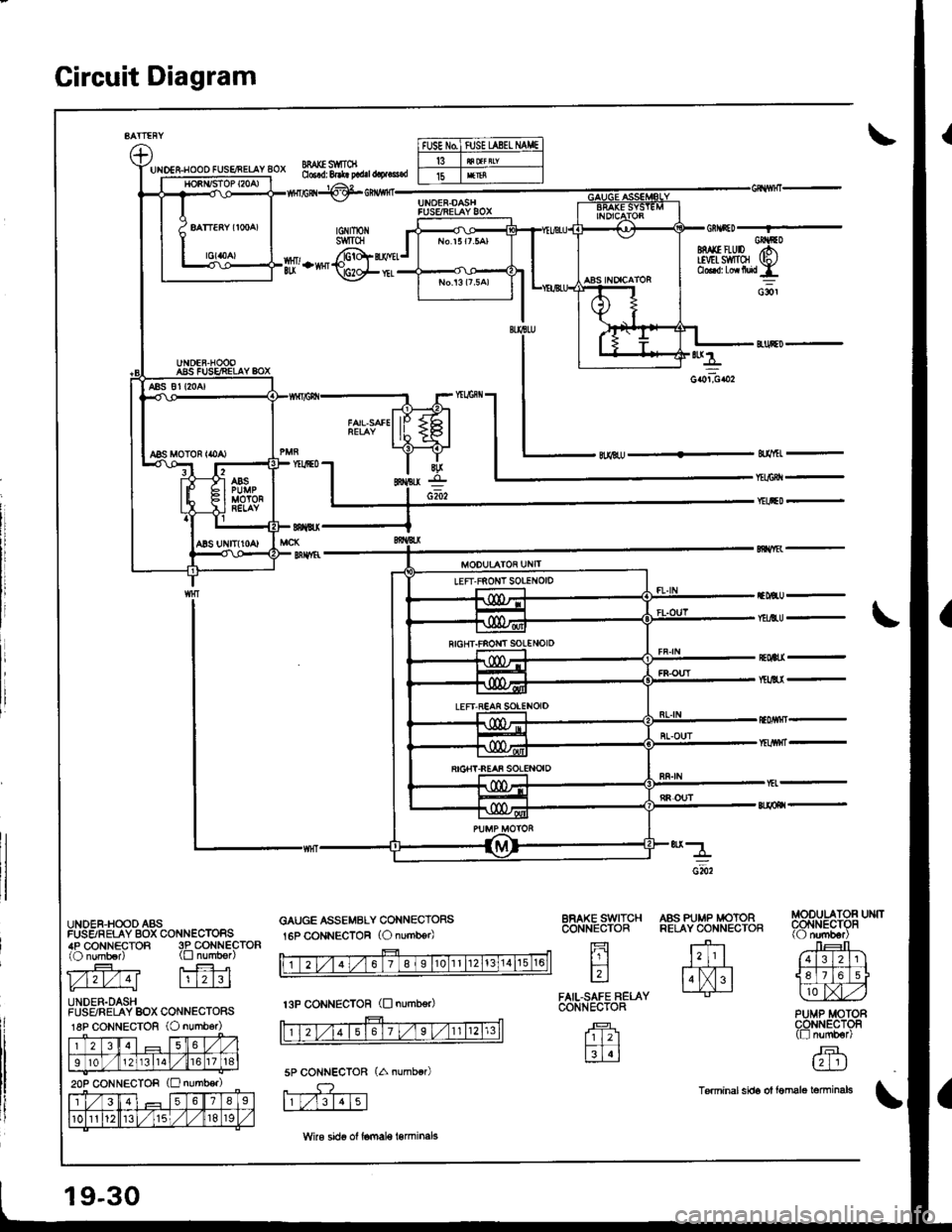
Gircuit Diagram
UIDES-HOOO FUSENELAY BOX
UNDER,HOOD ASSFUSSRELAY BOX CONN€CTORS4P CONNECTOR 3P CONNECTOR(O numb€r) (tr numb€r)
l./121./ 4l lrl2l3l
UNDER.DASHFUSFJRELAY BOX CONNECTORS18P CONNECTOR (O numb6r)
l235
I10121311a1,/67 t18
2op CONNECTOR (E number)
l356'78I
101l12/ 115t,/819
MAI(E S1IITCN06.d: 8.*! p.d.l @.!s.d
tGNtrotiSWITCH
p,-*@i
GAUGE ASSEMBLY CONNECTORS
16P CONNECTOR (O number)
SfMEL -
f,lBU -
Y&EtU -
*4
coiboz
EOWI-
BFAKE SWITCHCONNECTOR
fi
tr
FAIL,SAFE RELACONIiECTOR
Tr 121
M
A'ff.t#P;t"3.
ffi'
Jr:t r_E+?-|1]]
l.lXl. I tlL]jlJr:ly L-tr-J lLlAZ,)
PUMP MOTORCONNECTOF(tr numb€r)
,F.L?-]IJ
Tsrminal sids ol femalo tominals
5P CONNECTOR
f,rF-.Tt\
FUSE N0ftJSE UBEL IIAI,|E
15
t3P cONNEcToR (D numb€r)
19-30
Wke sido ol lomale l€rminels
Page 792 of 1681
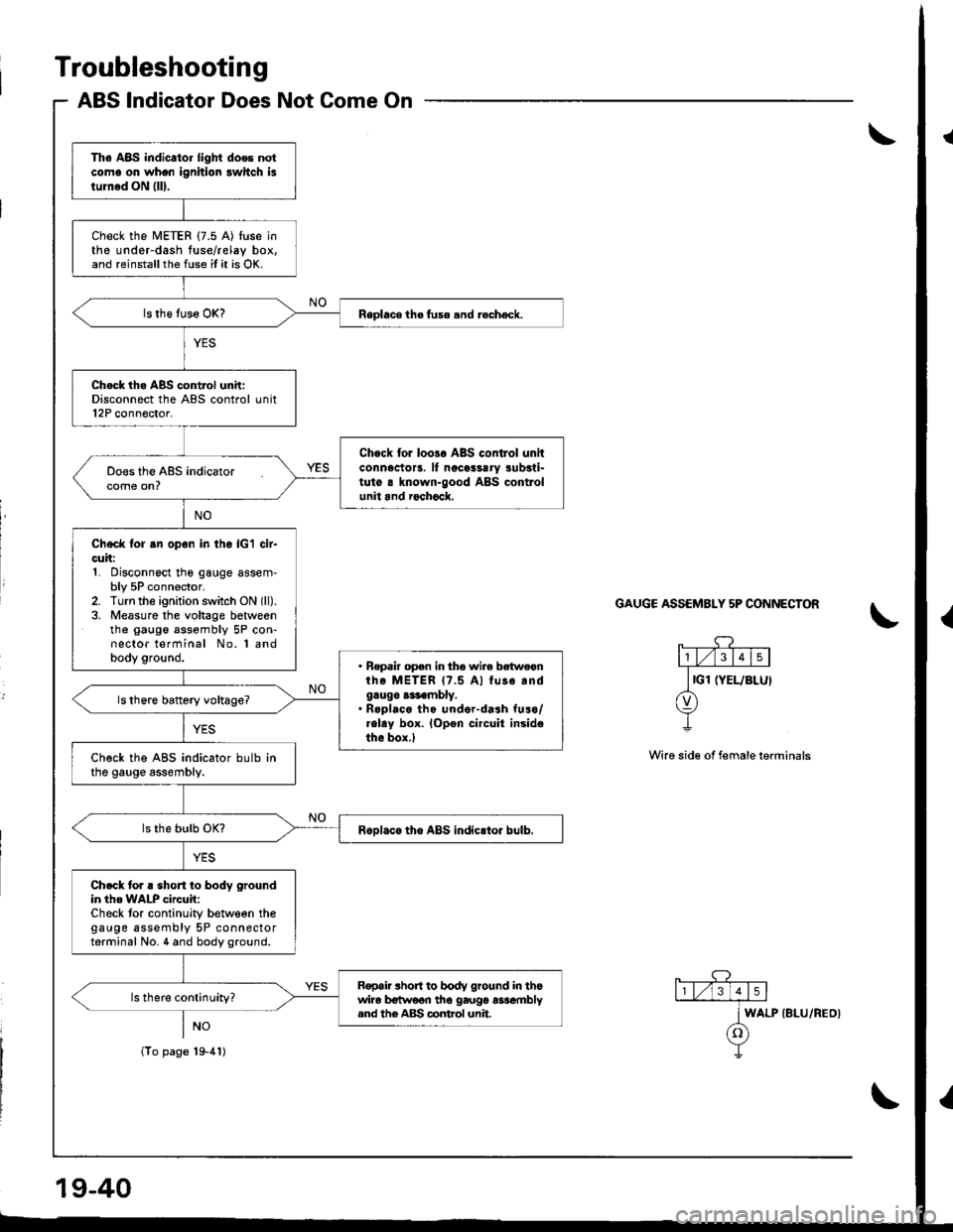
Troubleshooting
ABS lndicator Does Not Come On
\
GAUGE ASSEMBLY 5P CONNECTON
Wire sid€ of female terrninals
Th. A8S indicator light does notcoma on whon ignition swhch islum6d ON llll.
check the METER {7.5 A) tuse inthe under-dash tuse/relay box.and reinstallthe fuse it it is OK.
Replacsthefuse.nd recheck.
Ch.ck th. ABS control unit:Disconnect the ABS control unit12P connector.
Chock for loola ABS contlol unitconnector!. ll noco$rry !ubsti-tut6 a known-good ABS controlunit and r6chock.
Check tor .n opon in the lcl cir-cuit:1. Disconnect the gauge assem-bly 5P connector.2. Turn the ignition switch ON (ll).
3. Measure the voltage botweenthe gaugo assombly 5P con-nector terminal No. 'l andbody ground.. Repair open in tho wir. betwoanthe METER 17.5 A) tuso.ndgaugo a$embly.. R.pl.co tho under-dash furo/.elay box. lopen circuit insidethe box.l
check the A8s indicator bulb inthe gauge assembly.
R6olace tho ABS indicrtor bulb.
Ch.ck tor ! short to body groundin th6 WALP circuit:Check tor continuity b€tween thegauge assembly 5P connectorterminal No. 4 and body ground.
R€pair short to body ground in thowira b€tw6on tho gaug6 asscmblysnd the A&S control unit.
lTo page'19-41)
WALP {BLU/REO}
Page 794 of 1681
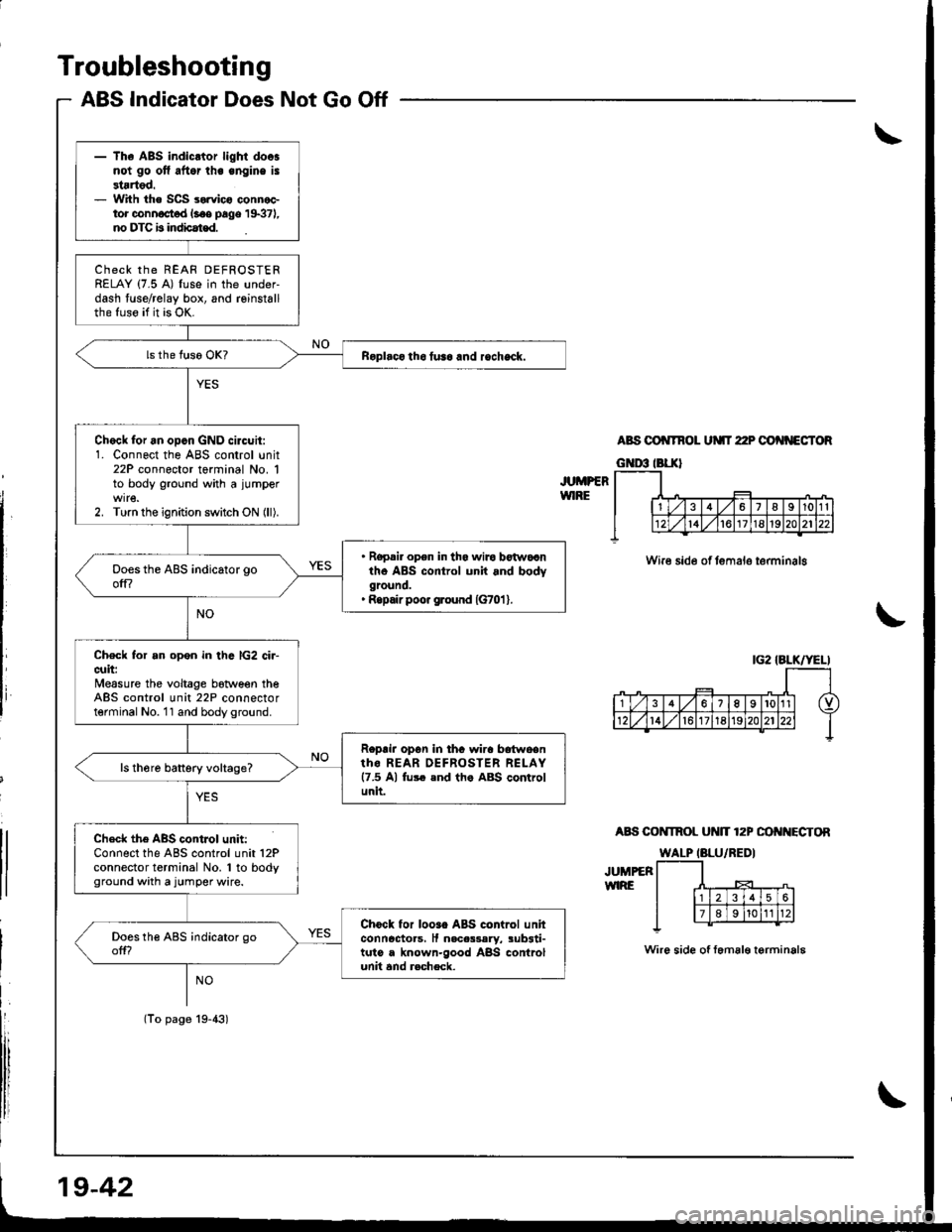
Troubleshooting
ABS Indicator Does Not Go Off
JUMPERWIRE
ABS OO TNOL UMT 22P OO'{NECTOR
Wire side of temalo terminalg
A8S COI{TROL Ut{lT 12P OO I{ECTOR
JUMPEFWIRE
Wire side of femal€ terminala
|G2 IALK/YELI
- The ABS indicltor light doosnot go ofl aftor lhe engine is3tartod.- With the SCS sorvico connoctor connoct d l.oe page 19371,no DTC b indbat€d.
ChECK thE REAF DEFROSTERRELAY (7.5 A) fuse in the under-dash fuse/relay box, and reinstallthe fuso if it is OK.
Roplaco tho tusa and rocheck.
Chock for an opcn GND circuit:1. Connect the ABS control unit22P connector terminal No. 1to body ground with a jumper
2. Turn the ignition switch ON (ll).
. Ropair opon in tha wiro botwocntho ABS control unit and bodyground.' Ropair poo. ground {G701 }.
Check for an open in thc lG2 ci.-cuit:Measure the voltage botween theABS control unit 22P connectorterminal No. 11 and body ground.
Roprir opon in thc wira bdtwoentho REAR OEFROSTER RELAY17.5 Al fu$ end th. ABS controlunit.
ls th6re battery voltage?
Check the ABS contJol unit:Connect the ABS control unit 12Pconnector terminal No. 1 to bodyground with a jumper wire.
Chock for looao ABS control unhconncctoas, It nacas3aly, sub3ti-tuto a known-good ABS controlunit and r.check.
(To page 19-43)
19-42