relay HONDA INTEGRA 1998 4.G Service Manual
[x] Cancel search | Manufacturer: HONDA, Model Year: 1998, Model line: INTEGRA, Model: HONDA INTEGRA 1998 4.GPages: 1681, PDF Size: 54.22 MB
Page 782 of 1681
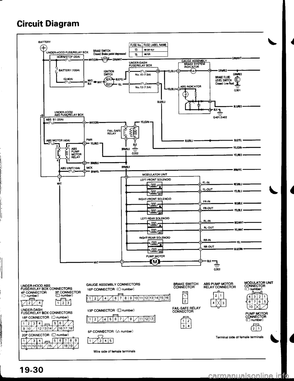
Gircuit Diagram
UIDES-HOOO FUSENELAY BOX
UNDER,HOOD ASSFUSSRELAY BOX CONN€CTORS4P CONNECTOR 3P CONNECTOR(O numb€r) (tr numb€r)
l./121./ 4l lrl2l3l
UNDER.DASHFUSFJRELAY BOX CONNECTORS18P CONNECTOR (O numb6r)
l235
I10121311a1,/67 t18
2op CONNECTOR (E number)
l356'78I
101l12/ 115t,/819
MAI(E S1IITCN06.d: 8.*! p.d.l @.!s.d
tGNtrotiSWITCH
p,-*@i
GAUGE ASSEMBLY CONNECTORS
16P CONNECTOR (O number)
SfMEL -
f,lBU -
Y&EtU -
*4
coiboz
EOWI-
BFAKE SWITCHCONNECTOR
fi
tr
FAIL,SAFE RELACONIiECTOR
Tr 121
M
A'ff.t#P;t"3.
ffi'
Jr:t r_E+?-|1]]
l.lXl. I tlL]jlJr:ly L-tr-J lLlAZ,)
PUMP MOTORCONNECTOF(tr numb€r)
,F.L?-]IJ
Tsrminal sids ol femalo tominals
5P CONNECTOR
f,rF-.Tt\
FUSE N0ftJSE UBEL IIAI,|E
15
t3P cONNEcToR (D numb€r)
19-30
Wke sido ol lomale l€rminels
Page 785 of 1681
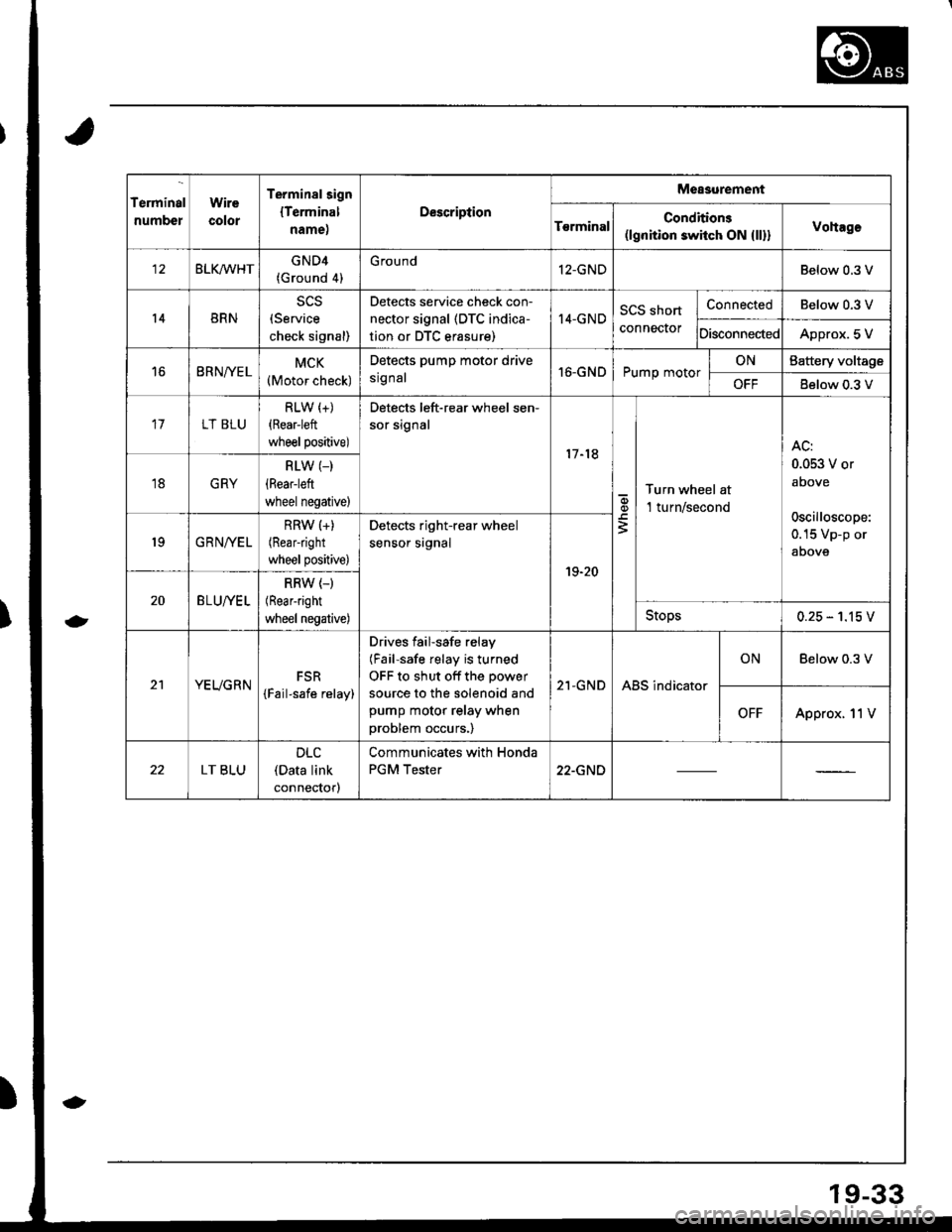
Terminal
numbel
Wire
color
Terminalsign
lTerminal
name,
Description
Measurement
T€rminalConditions(lgnition switch ON {ll}}Vohage
BLKMHTGND4(Ground 4)
G round12-GNDBelow 0.3 V
14BRN(Service
check signal)
Detects service check con-
nector signal (DTC indica-
tion or DTC erasure)
I4-GNDSCS short
connector
ConnectedBelow 0.3 V
DisconnectedApprox. 5 V
16BRNfYELMCK(Motor check)
Detects pump motor drive
srg nal16-GNDPump motorONBattery voltage
OFFBelow 0.3 V
17LT BLU
RLW (+)
{Rear-left
wheel positive)
Detects left-rear wheel sen-
sor signal
17-18
q,
3
Turn wheel at
l turn/second
AC:
0.053 V or
above
oscilloscope:
0.15 Vp-p or
aoove
18GRY
RLW (_)
(Rear-left
wheel negative)
19GRNIVEL
RRW (+)
(Rearright
wheel positive)
Detects right-rear wheel
sensor srgnal
19-20
20BLU//EL
RRW (-)
(Rear-right
wheel negative)Stops0.25 - 1.15 V
21YEUGRNFSR
{Fail-safe relay)
Drives failsafe relay
(Fail-safe relay is turned
OFF to shut off the power
source to the solenoid and
pump motor relay when
problem occurs.)
21-GNDABS indicator
ONBelow 0.3 V
OFFApprox. 11V
LT BLU
DLC(Data link
connectorl
Communicates with Honda
PGM Tester22-GND
19-33
Page 786 of 1681
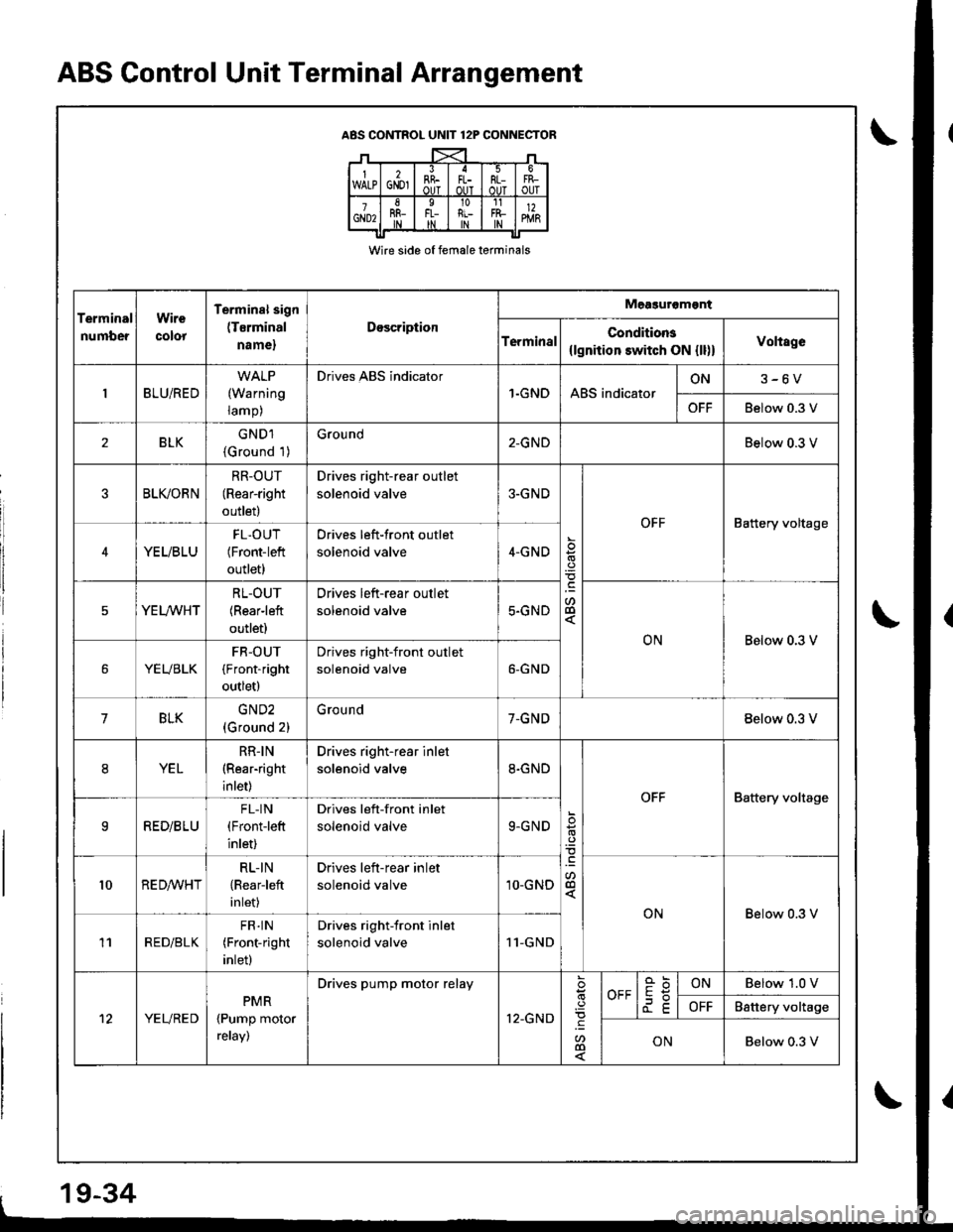
ABS Control Unit Terminal Arrangement
ABS CONTROL UNIT 12P CONNECTOR
Wire side of female terminals
Terminal
number
Wire
colot
Terminal sign
(Tsrminal
name,
Doscription
Measuromgnt
TerminalConditions
{lgnhion switch ON {ll)}Voltage
BLU/RED(Warning
ramp,
Drives ABS indicator
1.GNDABS indicatorON3-6V
OFFBelow 0.3 V
,BLKGNDl
{Ground 1)
Ground2-GNDBelow 0.3 V
BLI(ORN
RR-OUT(Rear-right
outlet)
Drives right-rear outlet
solenoid valve3-GND
a
OFFBattery voltage
YEUBLU
FL.OUT(Front-left
outlet)
Drives left-front outlet
solenoid valve4-GND
YEL/WHT
RL-OUT(Rearleft
outlet)
Drives left-rear outlet
solenoid valve5.GND
ONBelow 0.3 V
YEUBLK
FR-OUT
(Front-right
outlet)
Drives right-front outlet
solenoid valve6-GND
7BLKGND2
(Ground 2)
G rou nd7-GNDBelow 0.3 V
8YEL
RR-IN(Rear-right
inlet)
Drives right-rear inlet
solenoid valve8.GND
.9
-@
OFFBattery voltage
IRED/B LU
FL-IN(Front-left
inlet)
Drives left-front inlet
solenoid valve9-GND
l0RED/WHT
RL-IN
{Rearleft
inlet)
Drives left-rear inlet
solenoid valve1O-GND
ONBelow 0.3 V
11RED/BLK
FR] N(Front-right
inlet)
Drives right-front inlet
solenoid valve11-GND
't2YEURED
PMR
{Pump motor
retay)
Drives pump motor relay
12-GND.9
.EU'@
OFFdE
ONBelow 1.0 V
OFFBattery voltage
ONBelow 0.3 V
19-34
Page 787 of 1681
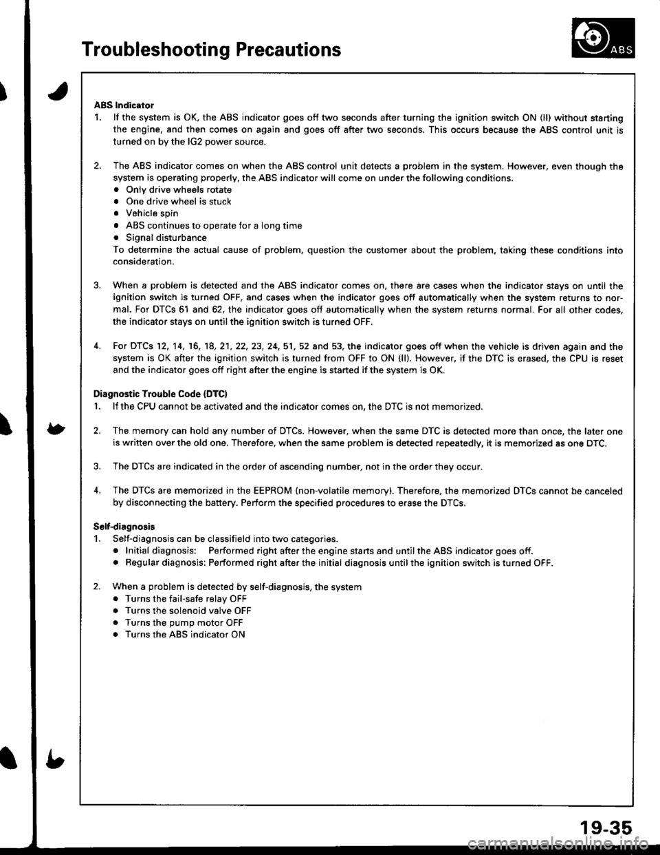
Troubleshooting Precautions
ABS lndicator
1. lf the system is OK. the ABS indicator goes off two seconds after turning the ignition switch ON (ll) without starting
the engine, and then comes on again and goes off after two seconds. This occurs because the ABS control unit is
turned on bv the lG2 oower source.
2. The ABS indicator comes on when the ABS control unit detects a problem in the system. However, even though the
system is operating properly, the ABS indicator will come on under the following conditions.. Onlv drive wheels rotate
. One drive wheel is stuck
. Vehicle spin
. ABS continues to operate for a long time
. Signal disturbance
To determine the actual cause of problem. question the customer about the problem, taking these conditions into
consideration.
3. When a problem is detected and the ABS indicator comes on, there are cases when the indicator stays on until the
ignition switch is turned OFF, and cases when the indicator goes off automatically when the system returns to nor-
mal. For DTCS 61 and 62, the indicator goes off automatically when the system returns normal. For all other codes.
the indicator stays on until the ignition switch is turned OFF.
4. For DTCS 12, 14, 16, '18, 2'1,22, 23, 24,51,52 and 53, the indicator goes off when the vehicle is driven again and the
system is OK after the ignition switch is turned from OFF to ON (ll). However, if the DTC is erased, the CPU is reset
and the indicator goes off right after the engine is started if the system is OK.
Diagnostic Trouble Code (DTC)
1. lf the CPU cannot be actlvated and the indicator comes on, the DTC is not memorized.
2. The memory can hold any number of DTCS. However, when the same DTC is detected more than once, the later one
is written over the old one. Therefore, when the same problem is detected repeatedly, it is memorized as one DTC.
3. The DTCs are indicated in the order of ascending number, not in the order they occur.
4, The DTCS are memorized in the EEPROM (non-volatile memory). Therefore, the memorized DTCS cannot be canceled
by disconnecting the battery. Perform the specified procedures to erase the DTCS,
S6lt-dirgnosis
1. Self-diagnosis can be classifield into two categories.
. Initial diagnosis: Performed right afterthe enginestansand untiltheABS indicator goes off.. Regular diagnosis: Performed rightafterthe initial diagnosis untilthe ignition switch isturned OFF.
2. When a problem is detected by self-diagnosis, the system
. Turns the fail-safe relay OFF
. Turns the solenoid valve OFF
. Turns the oumo motor OFF
. Turns the ABS indicator ON
Page 791 of 1681
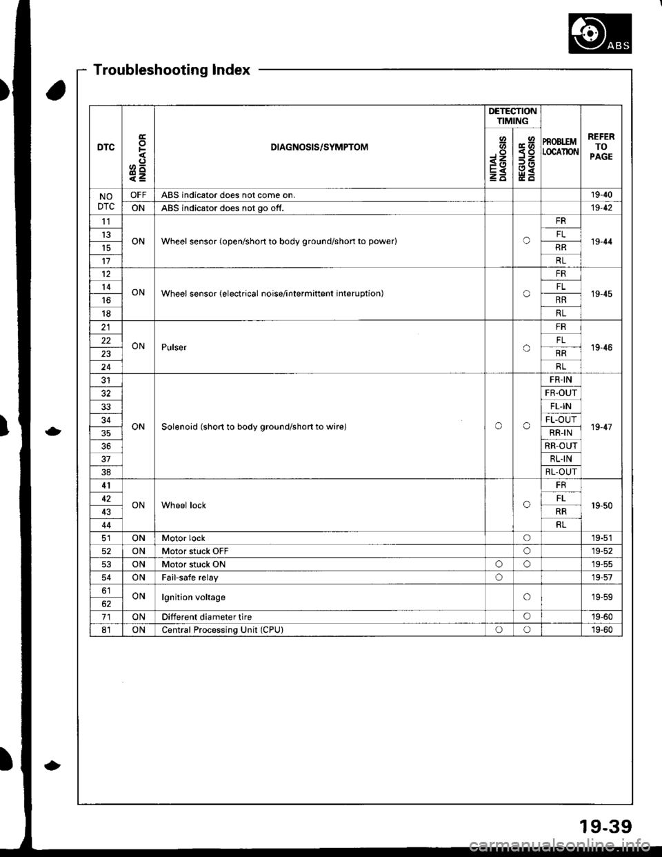
DTC
E
F
o^
e=
DIAGNOSIS/SYMPTOM
DETECTIONTIMING
PROBIEMLOCAIION
REFERTOPAGE
Io-<1
E
Y<
NODTC
OFFABS indicator does not come on.19-40
ONABS indicator does not go off.19-42
tl
ONWheel sensor (open/short to body ground/shon to power)o19-44t3FL
RR
17RL
12
ONWheel sensor (electrical noise/interminent interuption)o
FR
19-4514FL
16RR
18RL
ONPulsero
FR
19'4622
RR
24RL
ONSolenoid (short to body ground/shon to wire)oo
FR-IN
19-47
FR.OUT
33FL-IN
34FL-OUT
RR-IN
RR-OUT
37RL.IN
38RL-OUT
41
ONWheel locko19-5042FL
43RR
44RL
ONMotor locko19-51
52ONMotor stuck OFFo19-52
53ONMotor stuck ONoo19-55
54ONFailsafe relayo19-57
61ONlgnition voltageo19-59
71ONDifferent diameter tireo19-60
81ONCentral Processing Unit (CPU)oo19-60
Troubleshooting Index
19-39
Page 792 of 1681
Troubleshooting
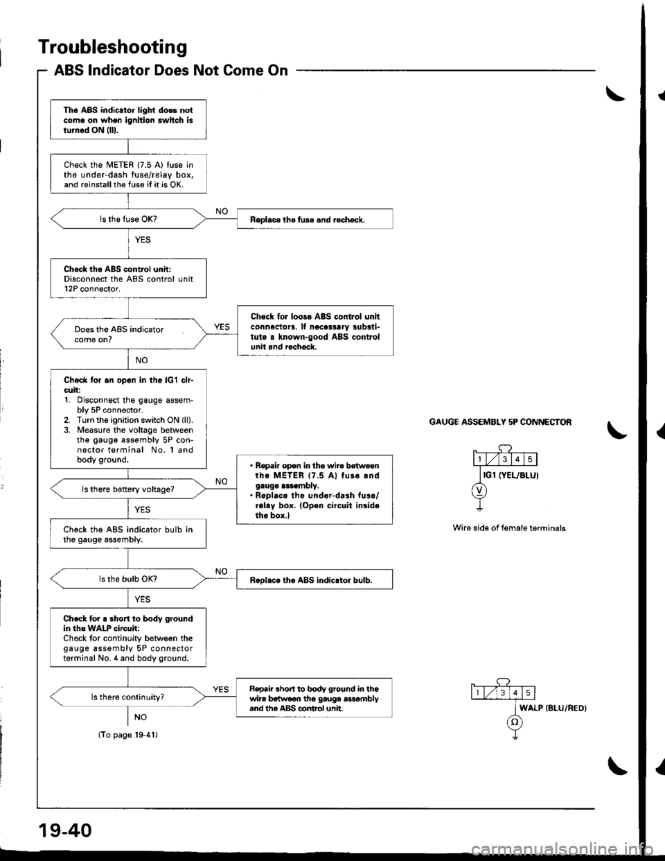
ABS lndicator Does Not Come On
\
GAUGE ASSEMBLY 5P CONNECTON
Wire sid€ of female terrninals
Th. A8S indicator light does notcoma on whon ignition swhch islum6d ON llll.
check the METER {7.5 A) tuse inthe under-dash tuse/relay box.and reinstallthe fuse it it is OK.
Replacsthefuse.nd recheck.
Ch.ck th. ABS control unit:Disconnect the ABS control unit12P connector.
Chock for loola ABS contlol unitconnector!. ll noco$rry !ubsti-tut6 a known-good ABS controlunit and r6chock.
Check tor .n opon in the lcl cir-cuit:1. Disconnect the gauge assem-bly 5P connector.2. Turn the ignition switch ON (ll).
3. Measure the voltage botweenthe gaugo assombly 5P con-nector terminal No. 'l andbody ground.. Repair open in tho wir. betwoanthe METER 17.5 A) tuso.ndgaugo a$embly.. R.pl.co tho under-dash furo/.elay box. lopen circuit insidethe box.l
check the A8s indicator bulb inthe gauge assembly.
R6olace tho ABS indicrtor bulb.
Ch.ck tor ! short to body groundin th6 WALP circuit:Check tor continuity b€tween thegauge assembly 5P connectorterminal No. 4 and body ground.
R€pair short to body ground in thowira b€tw6on tho gaug6 asscmblysnd the A&S control unit.
lTo page'19-41)
WALP {BLU/REO}
Page 794 of 1681
Troubleshooting
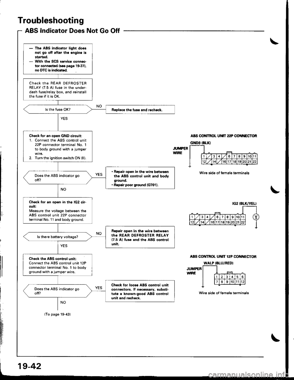
ABS Indicator Does Not Go Off
JUMPERWIRE
ABS OO TNOL UMT 22P OO'{NECTOR
Wire side of temalo terminalg
A8S COI{TROL Ut{lT 12P OO I{ECTOR
JUMPEFWIRE
Wire side of femal€ terminala
|G2 IALK/YELI
- The ABS indicltor light doosnot go ofl aftor lhe engine is3tartod.- With the SCS sorvico connoctor connoct d l.oe page 19371,no DTC b indbat€d.
ChECK thE REAF DEFROSTERRELAY (7.5 A) fuse in the under-dash fuse/relay box, and reinstallthe fuso if it is OK.
Roplaco tho tusa and rocheck.
Chock for an opcn GND circuit:1. Connect the ABS control unit22P connector terminal No. 1to body ground with a jumper
2. Turn the ignition switch ON (ll).
. Ropair opon in tha wiro botwocntho ABS control unit and bodyground.' Ropair poo. ground {G701 }.
Check for an open in thc lG2 ci.-cuit:Measure the voltage botween theABS control unit 22P connectorterminal No. 11 and body ground.
Roprir opon in thc wira bdtwoentho REAR OEFROSTER RELAY17.5 Al fu$ end th. ABS controlunit.
ls th6re battery voltage?
Check the ABS contJol unit:Connect the ABS control unit 12Pconnector terminal No. 1 to bodyground with a jumper wire.
Chock for looao ABS control unhconncctoas, It nacas3aly, sub3ti-tuto a known-good ABS controlunit and r.check.
(To page 19-43)
19-42
Page 800 of 1681
![HONDA INTEGRA 1998 4.G Service Manual Troubleshooting
DTC 31 - 38: Solenoid lcontd)
MODUTATOR UNIT CONiECTOR
RR-IN (YEL}RL-|N IREDAIHTI
JUMPEB WIRE
Terminal side ol female terminals
A8S CONTROL UN]T 12P CONNECTOR
FL.OUT(YEUELUI RL.OUT{Y HONDA INTEGRA 1998 4.G Service Manual Troubleshooting
DTC 31 - 38: Solenoid lcontd)
MODUTATOR UNIT CONiECTOR
RR-IN (YEL}RL-|N IREDAIHTI
JUMPEB WIRE
Terminal side ol female terminals
A8S CONTROL UN]T 12P CONNECTOR
FL.OUT(YEUELUI RL.OUT{Y](/img/13/6069/w960_6069-799.png)
Troubleshooting
DTC 31 - 38: Solenoid lcont'd)
MODUTATOR UNIT CONiECTOR
RR-IN (YEL}RL-|N IREDAI'HTI
JUMPEB WIRE
Terminal side ol female terminals
A8S CONTROL UN]T 12P CONNECTOR
FL.OUT(YEUELUI RL.OUT{YEL/WHTI
Wire side of ternale lermin6ls
FAIL.SAFE RELAY CONNECTOR
sout'lOtOr.H',rBRN/810 l-+l-]JUMPER I Lj-lJ
wRE I
Wire side of lemale terminals
(From page 19-47)
Check for an open in tha solonoidcircuit:1. Disconnect the mod u latorunit connector.2. Connect the appropriate solo-noid circuit torminal to bodyground with a jumper wire(see tabl€).3. Check for continuity betweenthe appropriate ABS controlunit 12P connector solenoidcircuit termina I and bodyground (see tabl€).
Rop.ir opon in th. lppropri.t.sol6noid circuit wira batwocnth. ABS control unit and modu-lltor unit.
Chack for an open in tho solonoid:1. Remove the jumper wire lromthe modulator unit connector.2. Connect the modulator unitconnector,3. Connect the fail-safe relay con-nector terminal No. 3 to bodyground with a jumper wirc.4. Check tho rosistance betweenthe appropriate ABS controlunit 12P connector terminaland body ground {see table).
ls the resistance OK?lN: 8- 10 020"C (68'F)
OUT:3-5o/20'C168'F)
Chock loi a 3hort to another wir.in the solonoid circuit:1. Disconnect the modulatorunit connector.2. Check for continuity betlveenthe appropriate ABS controlunit 12P connector terminaland all other solenoid circuitterminals (see table).
(To page 19-49)
DTC
Appropriate Terminal
ABS controlunit 12PModulatorunIconn€ctor
31: FRINNo. 11No. 1
32: FR-OUTNo.6No.5
33: FL-lNNo.9No.4
34: FL-OUTNo.4No.8
35r RRiNNo.8No.3
36: RR-OUTNo.3No.7
37: RLINNo. 10No.2
38: RL-OUTNo. 5No.6
ABS CONTROL UNIT 12P CONNECTOR
19-48
Wire side of lemale terminals
Page 804 of 1681
Troubleshooting
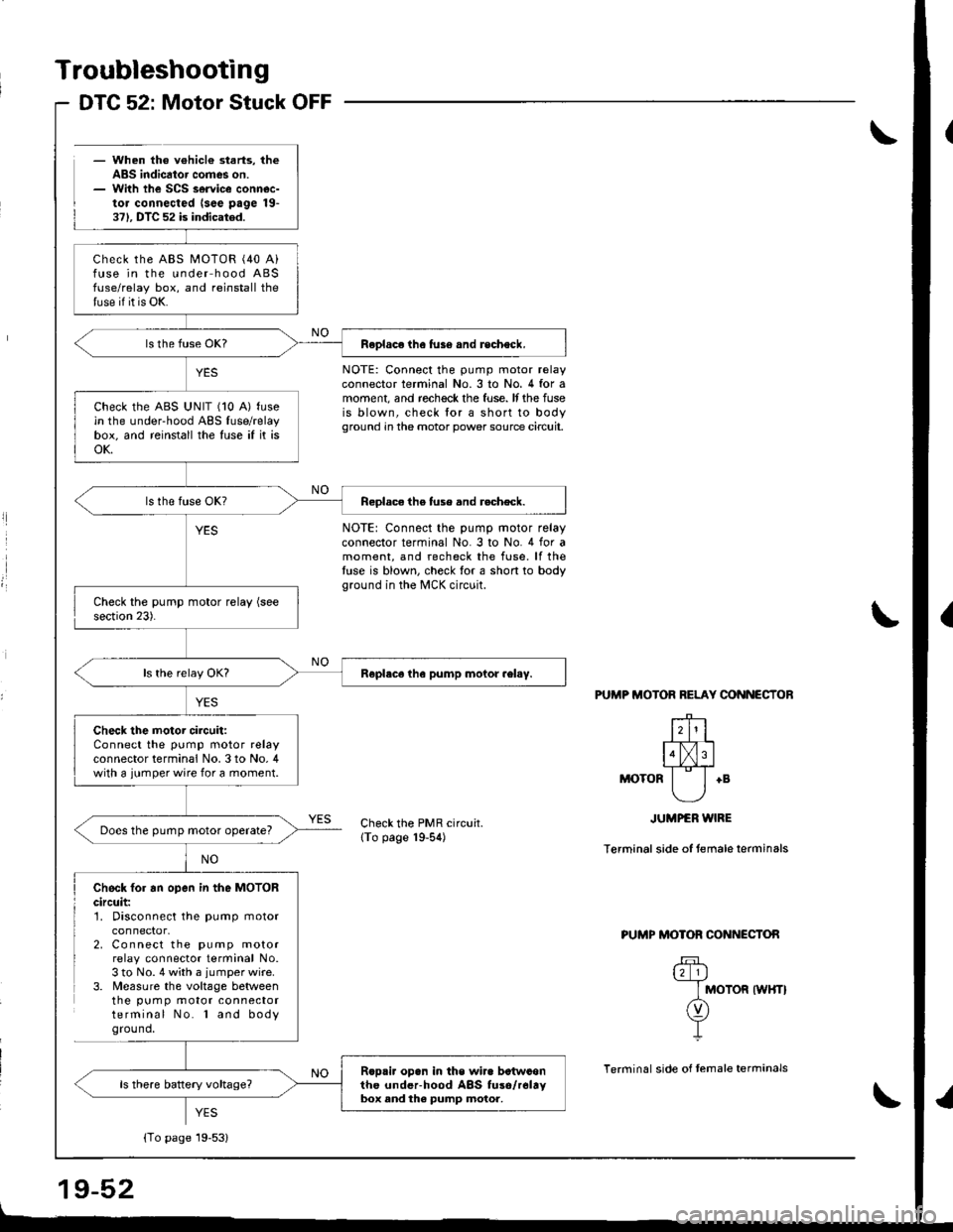
- When the v€hicl€ starts, theABS indicator comes on.- With the SCS service connec-tor connected lsee page 19-371. DTC 52 is indicated.
DTC 52: Motor Stuck OFF
l
l
NOTE: Connect the pump motor relayconnector terminal No.3 to No. 4 for amoment, and rechock the fuse. It the fuseis blown, check lor a short to bodyground in the motor power source circuit.
NOTE: Connect the pump motor relayconnector terminal No. 3 to No. 4 for amoment, and recheck the fuse. lf thetuse is blown, check for a short to bodyground in the MCK circuit.
PUTIIP MOTOR RELAY CONNECTOB
+B
Check the PMR circuit.lTo page 19-54)
JUMPER WIRE
Terminal side of temale terminals
Check fo. an open in the MOTORcircuit:1. Disconnect the pump motor
2. Connect the pump motorrelay connector terminal No.3 to No. 4 with a jumper wire.3. Measure the voltage betweenthe pum p motor connectorterminal No. l and bodyground,
PUMP MOTOR CONNECTON
u_l_lj
I MOTOR tWHTt
n)Y-L
Terminal side of temale terrninals
YES
Check the ABS MOTOR (40 A)fuse in the under hood ABSfuse/relay box, and reinstall thetuse if it is OK.
Feplace the fus6 and recheck.
check the ABS uNlT (10 A) fusein the under-hood ABS fuse/relaybox, and reinstall the fuse if it isoK.
Reolace the tuse and r.check.
Roplece tha pump motor .el.y.
Check the motor circuit:Connect the pump motor relayconnector terminal No. 3 to No, 4with a jumper wire for a moment.
Does the pump motor operate?
Rop.i. opan in the wir. betwconthc underhood ABS fuso/r6ltybox and the pump motor,
{To page 19-53}
Page 806 of 1681
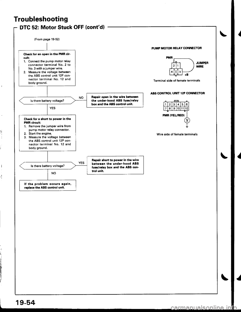
Troubleshooting
DTG 52: Motor Stuck OFF lcont'd)
PUMP ITIOTOR BELAY CONNECTOf,
JUMPERWIRE
Terminel side of female i€rminals
aBs oo tnol ut{tT 12P cof{f{EGToR
Wire side of lemale terminals
I
.t!
Ch.ck tor !n op.n in thc PMR cir-
cuit:1. Connoct tho pump motor relay
connector terminal No. 2 toNo.3 with a iumpor wir6.2, M€asure th6 voltage betw6entho A8S control unit 12P con-nector terminal No. 12 andbody ground.
R.p.ir op.n In th. wir. batw..nth. und.r-hood ABS tu../r.l.Ybox lnd th. ABS codrol unil.
Check lor a rho to pow.r in th.PMR circuii:1. Removo the jumper wire frompump motor relay connedor.2. Start the engine.3. ireasur6 the voltage betwoenth6 ABS control unit 12P con-nector terminal No. 12 8ndbody ground.
R.p.ir .hort to pow.r In th. wil.
brtwa!n lh. und..-hood ABSfur./r.l.y box rnd th. A8S con-trol unit.
ls th€re batt€ry voltage?
lf tha problam occura again,r.pllce th. ABS control unit.