relay HONDA INTEGRA 1998 4.G Owner's Guide
[x] Cancel search | Manufacturer: HONDA, Model Year: 1998, Model line: INTEGRA, Model: HONDA INTEGRA 1998 4.GPages: 1681, PDF Size: 54.22 MB
Page 467 of 1681
![HONDA INTEGRA 1998 4.G Owners Guide Troubleshooting Procedures
Checking the Diagnostic Trouble Code (DTC)
with an OBD ll Scan Tool or th€ Honda PGM Tester
When the TCM senses an abnormality in the input or output systems, the lD,] ind HONDA INTEGRA 1998 4.G Owners Guide Troubleshooting Procedures
Checking the Diagnostic Trouble Code (DTC)
with an OBD ll Scan Tool or th€ Honda PGM Tester
When the TCM senses an abnormality in the input or output systems, the lD,] ind](/img/13/6069/w960_6069-466.png)
Troubleshooting Procedures
Checking the Diagnostic Trouble Code (DTC)
with an OBD ll Scan Tool or th€ Honda PGM Tester
When the TCM senses an abnormality in the input or output systems, the lD,] indicator light in the gauge assembly will
blink. When the 16p Data Link Connector (DLC) (located under the dash on the passenger side) is connected to the OBD ll
Scan Tool or Honda PGM Taster as shown, the scan tool or tester will indicate the Diagnostic Trouble Code (DTC) when
the ignition switch is turned ON {ll}.
When the !r indicator light has been reported on, connect the OBD ll Scan Tool confirming to SAE J1978 or Honda PGM
Tester to the DLC (16P) behind the ashtray. Turn the ignition switch ON (ll) and observe the DTC on the screen ofthe OBD
ll Scan Tool or Honda PGM Tester. After determining the DTC, refer to the electrical system Symptom-to-Component
Chart on pages 14-54 and 14-55.
NOTE: SeetheOBDll ScanTool orHonda PGM Tester user's manual for specific instructions.
OBD-IlSCAN TOOL orHONDA PGM TESTER
Some PGM-Fl problems will also make the lol indicator light come on. After repairing the PGM-Fl system. disconnect the
BACK Up fuse (7.5 A) in the under-hood fuse/relay box for more than 10 seconds to reset the TCM memory, then recheck.
NOTE: Disconnecting the BACK UP fuse also cancels the radio anti-theft code, preset stations and the clock setting. Get
the customer's code number, and make note of the radio presets before removing the fuse so you can reset them
uJ trr
ulu
ai
14-50L
DATA LINK CONNECTOR (16P)
I
il
lt
rJq
Page 468 of 1681
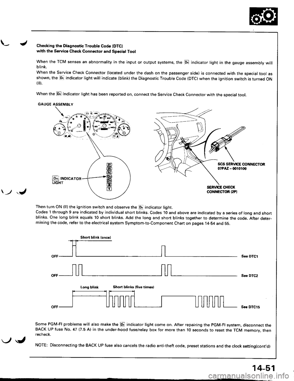
L./Checking th€ Diagnostic Trouble Codo (DTC)
with the Sowica Check Connector and Special Tool
When the TCM senses an abnormality in the input or output systems, the [D;l indicator light in the gauge assembly willblink.
When the Service Check Connector (located under the dash on the passenger side) is connected with the special tool asshown, the E1T indicator light will indicate (blink) the Diagnostic Troubte Code (DTC) when the ignition switch is turned ON{
}.
When the @ indicator light has been reported on, connect the Service Check Connector with the special toot.
GAUGE ASSEMEI.Y
Then turn ON (ll) the ignition switch and observe the E indicator light.Codes 1 through 9 are indicated by individual short blinks. Codes 1O and above are indicated by a series of long and shortblinks. One long blink equals 10 short blinks. Add the long and short blinks together to determine the code. After deter-mining the code, refer to the electrical system Symptom-to-Component Chart on pages 14-S4 and 55.
\-F;ii^r
) ,J
Se. OTCI
Soo DTC2
Long blinkShort blinb lfive timcsl
Soe DTCl5
Some PGM-FI problems will also make the E indicator light come on. After repairing the PGM-FI system, dasconnect theBACK UP fuse No. 47 (7.5 A) in the under-hood tuse/relay box for more than 1O seconds to reset the TCM memory, thenrecnecK.
NOTE; Disconnecting the BACK UP fuse also cancels the radio anti-theft code, preset stations and the clock setting(cont,d)
Short blink loncsl
\-/ \i,
14-51
Page 470 of 1681
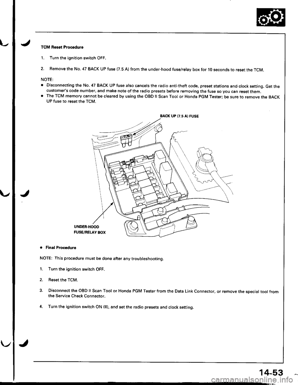
TCM Reset Procodure
1. Turn the ignition switch OFF.
2. Remove the No. 47 BACK UP fuse {7.8 A) from the under-hood fuse/relay box for lO seconds to reset the TCM.
NOTE:
. Disconnecting the No, 47 BACK UP fuse also cancels the radio anti-theft code, preset stations and clock setting, Get thecustomer's code number, and make note of the rsdio presets before removing the fuse so you can reset them.o The TCM memory cannot be cleared by using the OBD ll Scan Tool or Honda pGM Tester; be sure to remove the BACKUP fuse to reset the TCM.
BACK UP (7.5 A) FUSE
J
UNDER.HOOD
FUSE/RELAY BOX
. Final Procodurs
NOTE: This procedure must be done after any trou bleshooting.
1. Turn the ignition switch OFF.
2. Reset the TCM.
3. Disconnect the OBD ll Scan Tool or Honda PGM Tester from the Data Link Connector, or remove the sDecial tool fromthe Service Check Connector.
4. Turn the ignition switch ON (ll), and set the radio presets and clock setting.
14-53
Page 472 of 1681
u.drrf,,
J
J
J
14-55
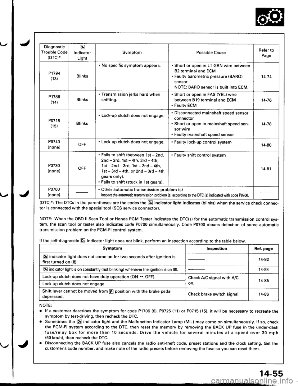
Diagnostic
Trouble Code(DTC).
Ej
lndicator
Light
SymptomPossible CauseRefer to
Page
P1794
(131Blinks
. No specific symptom appears.. Short or open in LT GRN wire between
82 terminal and ECM. Faulty barometric pressure (BARO)
sensor
NOTE: BARO sensor is built into ECM.
't 4-7 4
P1786
(14)Blinks
. Transmission jerks hard when
shifting.
Short or open in FAS (YEL) wire
between 819 terminal and ECM
Faulty ECM
14-76
P0715
(15)Blinks
. Lock-up clutch does not engage,Disconnected mainshaft speed sensor
connector
Short or open in mainshaft speed sen-
sor wrre
Faulty mainshaft speed senso.
14-74
P0740
{ none,OFF. Lock-up clutch does not engage.Faulty lock-up control system14-80
P0730
I none,
. Fails to shift (between lst - 2nd,
2nd - 3rd, 1st - 4th. 3rd - 4th,
1st - 2nd - 3rd, 1st - 2nd - 4th,
1st - 3rd - 4th, or 2nd - 3rd - 4th
gears onry).. Fails to shift (stuck in 1st gears).
. Faulty shift control system
14-81
P0700
(none)
. Other automatic transmission problem (s)
Inspeclthe a utomatic transmission problem (s)accordingto the DTC (s)indicated with code m700.
(DTC)*: The DTCS in the parentheses are the codes the E indicator light indicates (blinks) when the service cnecK connec-tor is connected with the sDecialtool {SCS service connector).
NOTE: WhentheOBDll Scan Tool orHonda PGM Tester indicates the DTC(S) for the automatic transmission control sys-
tem, the scan tool or tester also indicates code P0700 simultaneously. Code P0700 means detection of some automatic
transmission problem on the PGM-Fl control system.
lf the self-diagnostic E indicator light does not blink. perform an inspection according to the table below.
NOTE:
. lf a custombr describes the symptom for code P1706 (6), P0725 (11) or P0715 (15), it will be necessary to recreate the
symptom by test-driving, then recheck the DTC,. Sometimes the E indicator light and the Malfunction Indicator Lamp (MlL) may come on simultaneously. lf so, check
the PGM-Fl system according to the DTC, then reset the memory by removing the BACK UP fuse in the under-dash
fuse/relay box for more than l0 seconds. Drive the vehicle for several minutes at a speed over 30 mph(50 km/h). then recheck the DTC.
. Disconnecting the BACK UP fuse also cancels the radio anti-theft code, preset stations and the clock setting. Get the
customer's code number, and make note of the radio presets before removing the fuse so you can reset them.
SymptomInspectionR€f. page
E indicator light does not come on for two seconds after ignition is
first turned on (ll).14-42
E indicator light is on constantly (not blinking) wheneverthe ignition is on {ll).14-84
Lock-up clutch does not have duty operation (ON - OFF).Check A,/C signal with Ay'C
on.14-85Lock-up clutch does not engage.
Shift lever cannot be moved from E position with the brake pedal
oeDresseo.Check brake switch signal.14-86
Page 498 of 1681
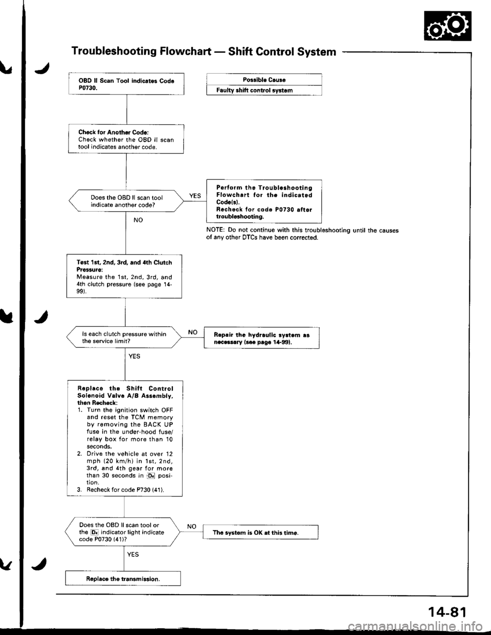
Troubleshooting Flowchart - Shaft Control System
NOTE: Do not continue with this troubleshootlng until the causesof any other DTCS have been corrected.
Chock foi Another Code:Check whether the OBD ll scantool indicates another code.
Psrtorm tho Tioubla3hootingFlowch.rt fo. th. indicatodCodcl.l.Rechsck tor code P0730 attoltroublolhooting.
Does the OBD ll scan toolindicate anothor code?
Tost 1st, 2nd, 3rd, and 4th ClutchProssuro:Measure the 1st,2nd,3rd, and4th clutch pressure (see page 14-
ls each clutch pressure withinthe service limit?R.p!ir lhG hydraulic ry3t.m ranac.3!.ry l3€e pago 1+991.
Roplace the Shilt ContiolSolonoid Valve A/B Assombly,thon Recheck:1. Turn the ignition switch OFFand reset the TCM memoryby removing the BACK UPfuse in the under-hood fuse/relay box for more than '10
seconds.2. Orive the vehicle at over 12mph (20 km/h) in lst,2nd,3rd, and 4th gear for morethan 30 seconds in E posi-tion.3, Recheck for code P730 (41).
Does the OBD llscan toolorthe E indicator light indicatecode P0730 (4'1)?Tho systom is OX etthi3 timo.
Poitible C.uBe
F""lty "hlft ".^t..t ",/"t".
Page 650 of 1681
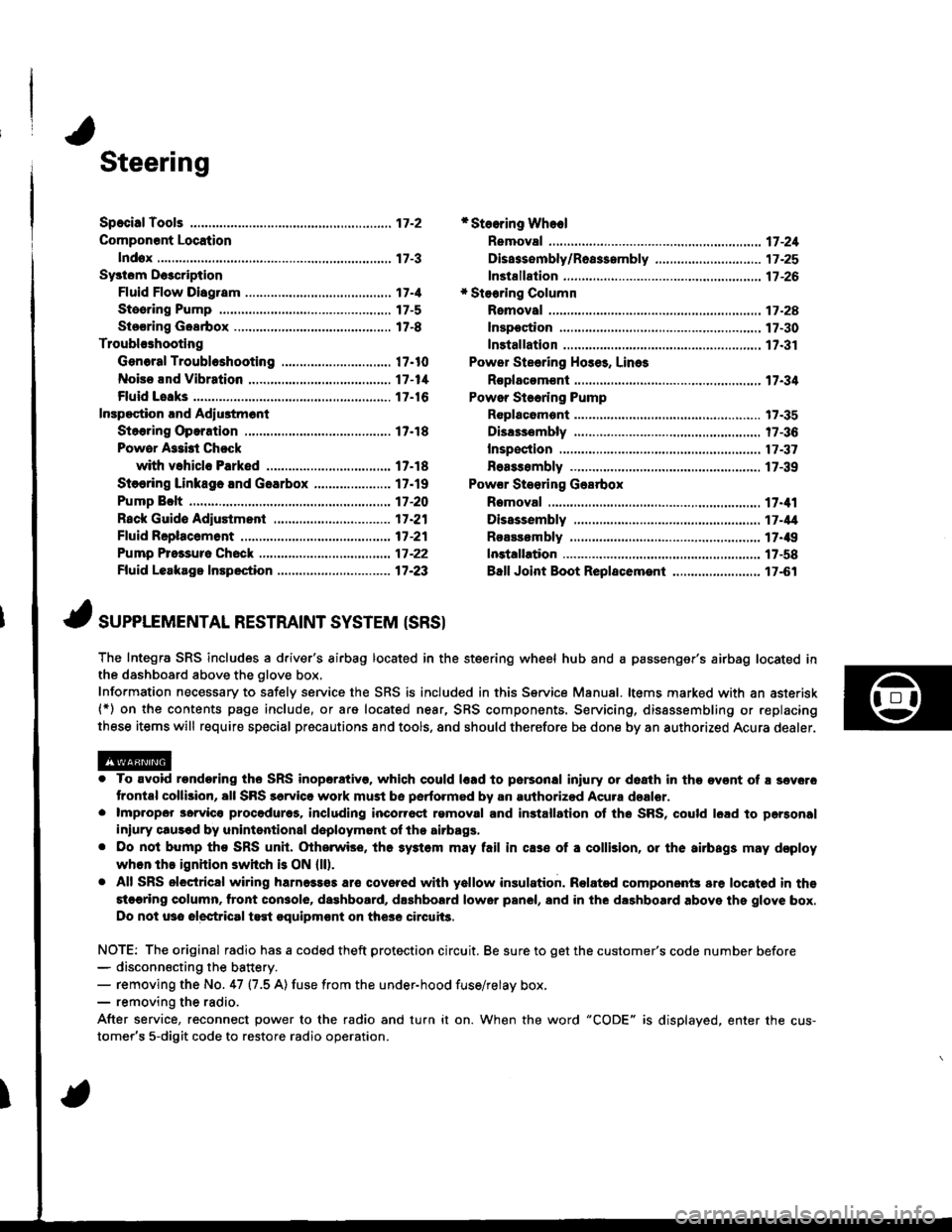
Steering
Componsnt Location
lndox
*Stooring Wheel
Removal ....
Disassombly/Ro8$.mbly
Disassombly ......
F08$€mbly
Powcr Stosring Gosrbox
R6moval
............................ 17-3
............. 17 -1
................ 17-16
............................. 17_25
17-30
17.31
.......17-21
Sy3tom DGcription
Fluid Flow Disgram
Steering Pump .............. 17-5
Stocring Goarbox ...17.8
Troublorhooting
Gonoral Troubleshooting .............................. 17.10
Noiso lnd Vibration ...... 17-1i[
Fluid Losk3
lnspoction
Installation
Powor Steering Hos6, Lino3
Roplacom€nt .................. 17.34
Powor Steoring Pump
RGplac6montlolpeqtion lnd Adiu3tm6nl
Stoo.ing Operation
Powor A$bi Chock
with v.hiclo Parked
Stcering Linkage 6nd Goarbox
Pump Bolt
17.18
17.18
17.19
17-20
17.35
t7-36
17 -37
r7-39
Inspoction
................... 17.41
Rack Guide Adiustmont ..........................-.-.-. 17 -21
Ffuid Rcplacemont ........17-21
Pump Prc&suro Chock ...,........................,..,..., 17 -22
Fluid Leakage Inrpection ............................... 17-23
Dissssembly
R€aEs€mbly
In3tallation........... 17_58
Ball Joint Boot Replacem.ni ........................ 17-61
17-U
17.49
J ,urrar*TNTAL REsrRArNr sysrEM (sRsr
The Integra SRS includes a driver's airbag located in the steering wheel hub and a passenger's airbag located inthe dashboard above the glove box,
Information necessary to safely service the SRS is included in this Service Manual. ltems marked with an asterisk(*) on the contents page include, or are located near, SRS components. Servicing, dissssembling or replacing
these items will require special pr6cautions and tools, and should therefore be done by an authorized Acura dealer.
. To avoid rondoring ths SRS inoparstivo. which could |rad to parsonal iniury or doath in the ov€nt of ! sev6.o
trontal collision, all SRS sarvice work must be perto.med by an authorizod Acura dsalor.. lmpropor 3orvic€ procadures, including inco[6ql rgmoval and inrtallation of the SRS, could l6ad to pgrsonal
iniury clus€d by unintentional doployment of the airbags,. Do nol bump tho SRS unh, (Xherwise, th6 3ystom may fail in cas€ ol a collision, or the airbags may d€ploy
when ths ignition switch is ON {ll).. All SRS electrical wiring harness€s aro covered with yallow insulation. Related component3 are located in ths
stcaring column. tront con3ol6, dashboard, d.shbolrd lower panel, and in the dashboard above ths glove box.
Do not u3o electrical test oquipm€nt on the3e circuii3.
NOTE: The original radio has a coded theft protection circuit. Be sure to get the customer's code number before- disconn€cting the battery.- removing the No. 47 (7.5 A) fuse from the under-hood fuse/relay box,- removing the radio.
After service, reconnect power to the radio and turn it on. When the word "CODE" is displayed. enter the cus-
tomer's 5-digit code to restore radio operation.
Page 678 of 1681
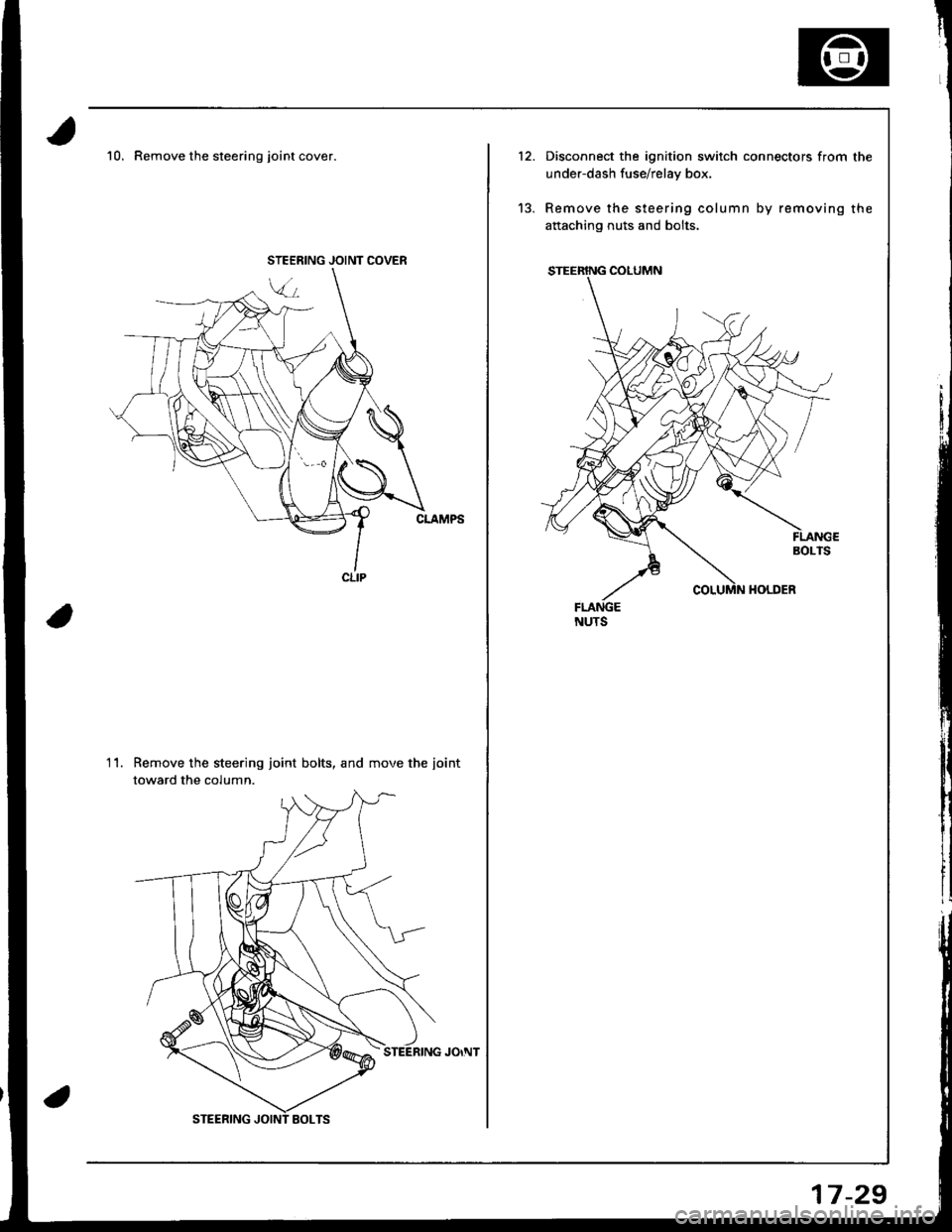
10. Remove the steering joint cover.
Remove the steering joint bolts, and move the iointtoward the column.
11.
JOINT COVER
12.
'13.
Disconnect the ignition switch connectors from the
under-dash fuse/relay box.
Remove the steering column by removing the
aftaching nuts and bolts.
17-29
Page 682 of 1681
9.
1.
8.
11.
10.
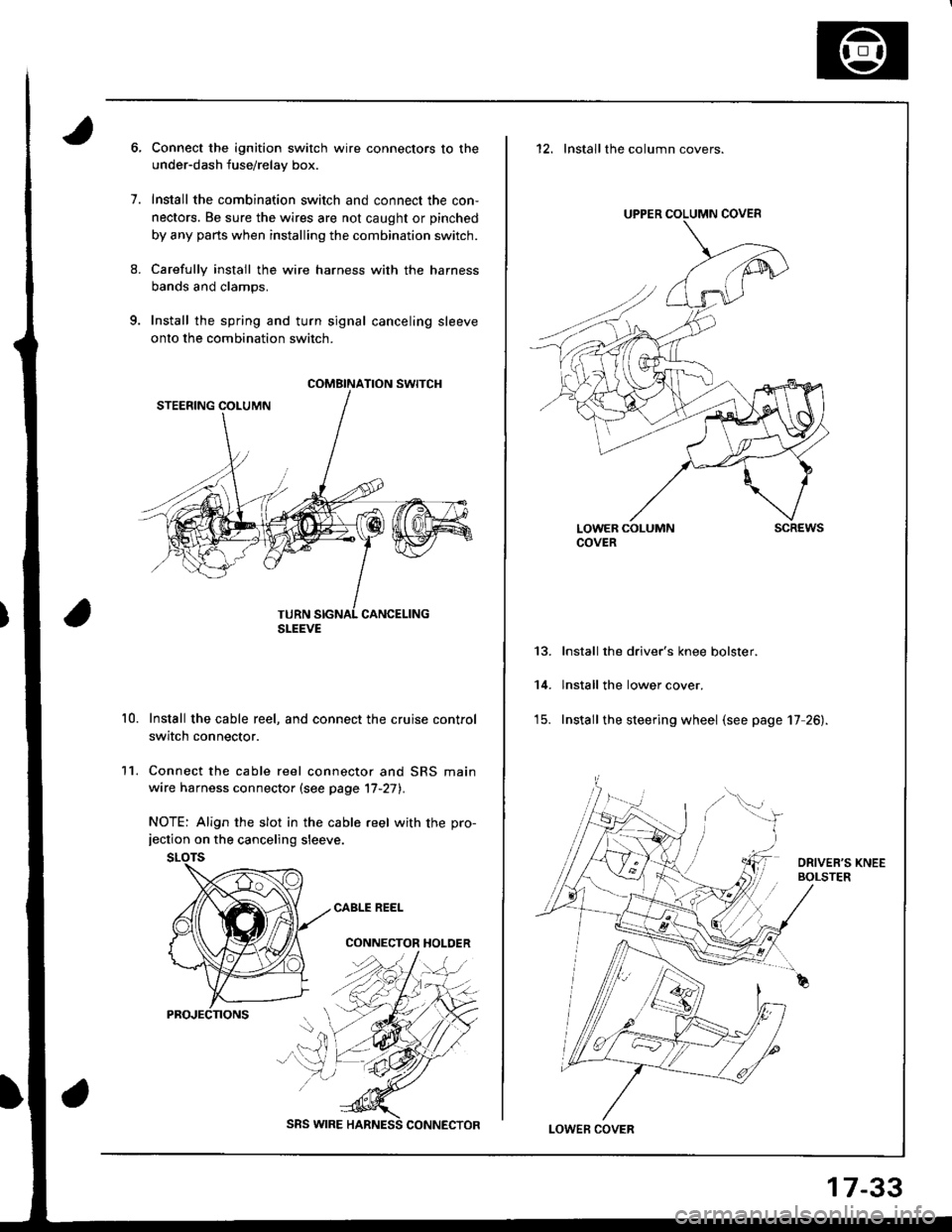
Connect the ignition switch wire connectors to the
under-dash fuse/relay box.
Install the combination switch and connect the con,
nectors. Be sure the wires are not caught or pinched
by any parts when installing the combination switch.
Carefully install the wire harness with the harness
bands and clamps.
Install the spring and turn signal canceling sleeve
onto the combination switch.
Install the cable reel, and connect the cruise control
switch connector.
Connect the cable reel connector and SRS main
wire harness connector (see page '17-27).
NOTE: Align the slot in the cable reel with the pro-jection on the canceling sleeve.
CABLE REEL
CONNECTOR HOLDER
COMBINATION SWITCH
SLEEVE
SRS WIRE
17-33
12. Installthe column covers.
UPPER COLUMN COVER
LOWER COLUMNCOVERscREws
13.
14.
Install the driver's knee bolster.
lnstall the lower cover.
Install the steering wheel (see page 17 26).
LOWEF COVER
Page 775 of 1681
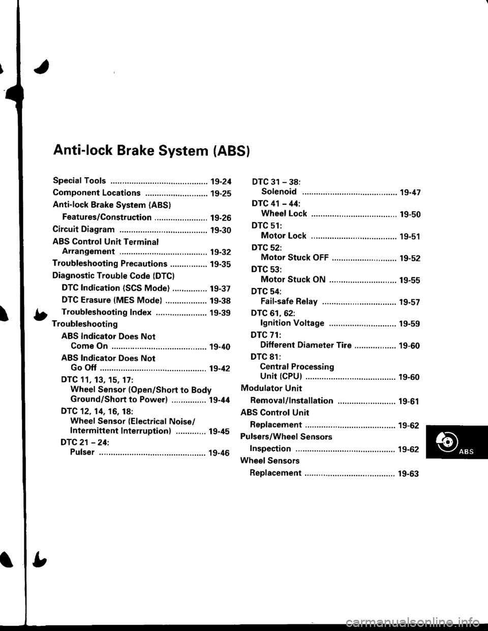
Anti-lock Brake System {ABS}
Speciaf Tools ............... 19-24
Component Locations,...........,..,........... 19-25
Anti-lock Brake System (ABSI
Features/Construction ....................... 19-2G
Circuit Diagram ........... 19-30
ABS Control Unit Terminal
Arrangement ........... 19-32
Troubleshooting Precautions ................ 1g-35
Diagnostic Trouble Code (DTC)
DTC Indication (SCS Mode) ............... t9-37
DTC Erasure {MES Mode) .................. 19-38
b Troubleshooting Index ...................... 19-39- Troubleshooting
ABS Indicator Does Not
Come On .............. 19-40
ABS Indicator Does Not
Go Off .............. ..... 19-42
DTC 11, 13, 15. 17:
Wheel Sensor (Open/Short to Body
Ground/Short to Power) ............... l9-44
DTC 12. 14, 16, 18:
Wheel Sensor (Electrical Noise/
Intermittent Interruption) ..........,.. 19-45
DTC21 -24:
Pulser ...,.......... ..... 19-46
DTC 31 - 38:
Solenoid .............. 19-47
DTC 41 - 44:
Wheel Lock .......... 19-50
DTC 51:
Motor Lock .......... 19-51
DTC 52:
Motor Stuck OFF ...................,........ 19-52
DTC 53:
Motor Stuck ON ............................. 19-55
DTC 54:
Fail-safe Relay ................................ t9-57
DTC 61.62:
lgnition Voltage ............................. 19-59
DTC 71:
Different Diameter Tire .................. 1 9-60
DTC 81:
Gentral Processing
Unit {CPU} ............ 19-60
Modulator Unit
Bemoval/lnstallation ......................... 19-61
ABS Control Unit
Replacement ............ 19-62
Pulsers/Wheel Sensors
Inspection ................ 19-62
Wheel Sensors
Replacement .,.......... 19-63
Page 777 of 1681
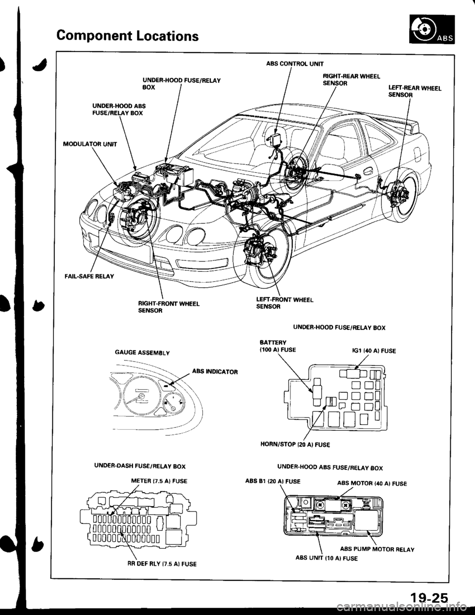
Gomponent Locations
,)
ABS CONTROL UNIT
UNDER.HOOD FUSE/RELAYRGHT-NEAR WHEELsEillioRaoxLEFT.REAR WHEEI-SENSOR
UNDER-H(X)D ABS
MODULATOR UNIT
FAIL-SAFE RELAY
RIGHT-FRONT WHEELSENSOR
LEFT-FROl{T WHEELSENSOR
UNDER.HOOD FUSE/RELAY BOX
ABS INDICATOR
UNDER.HOOD ABS FUSE/RELAY 8OX
ABS 81 {20 AI FUSEAAS MOTOR {40 Al FUS€
AAS PUMP MOTOR RELAY
GAUGE ASSEMBLY
!D
Dtrt]
HORN/STOP I2O A) FUSE
A8S UNIT {10 AI FUSERR DEF FI-Y I7.5 AI FUSE
19-25