relay HONDA INTEGRA 1998 4.G Manual PDF
[x] Cancel search | Manufacturer: HONDA, Model Year: 1998, Model line: INTEGRA, Model: HONDA INTEGRA 1998 4.GPages: 1681, PDF Size: 54.22 MB
Page 1029 of 1681
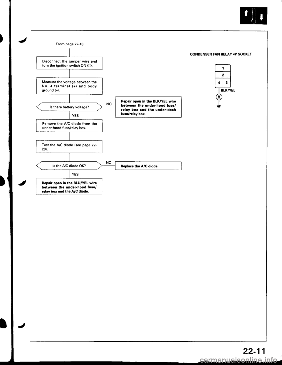
Disconnect the jumper wire andturn the ignition switch ON (ll).
Measu16 tho voltagg botween theNo.4 terminal {+) and bodyground (-),
R.prir op.n In th. BLK/YEL wir.batwaen tha undar-hood fuaa/ral.y box and tho undar.daahfuro/rclay box.
R€move the A,/C diode from thsund6r-hood tuso/relav box.
ls the A,/C diode OK?
R.prir op.n in tha BLU/YEL wir.batw..n th. und.r.hood tu../rol.y box .nd th. A/C dlod..
From page 22-10
CONDENSER FAN RELAY IP SOCKET
I
22-1
Page 1031 of 1681
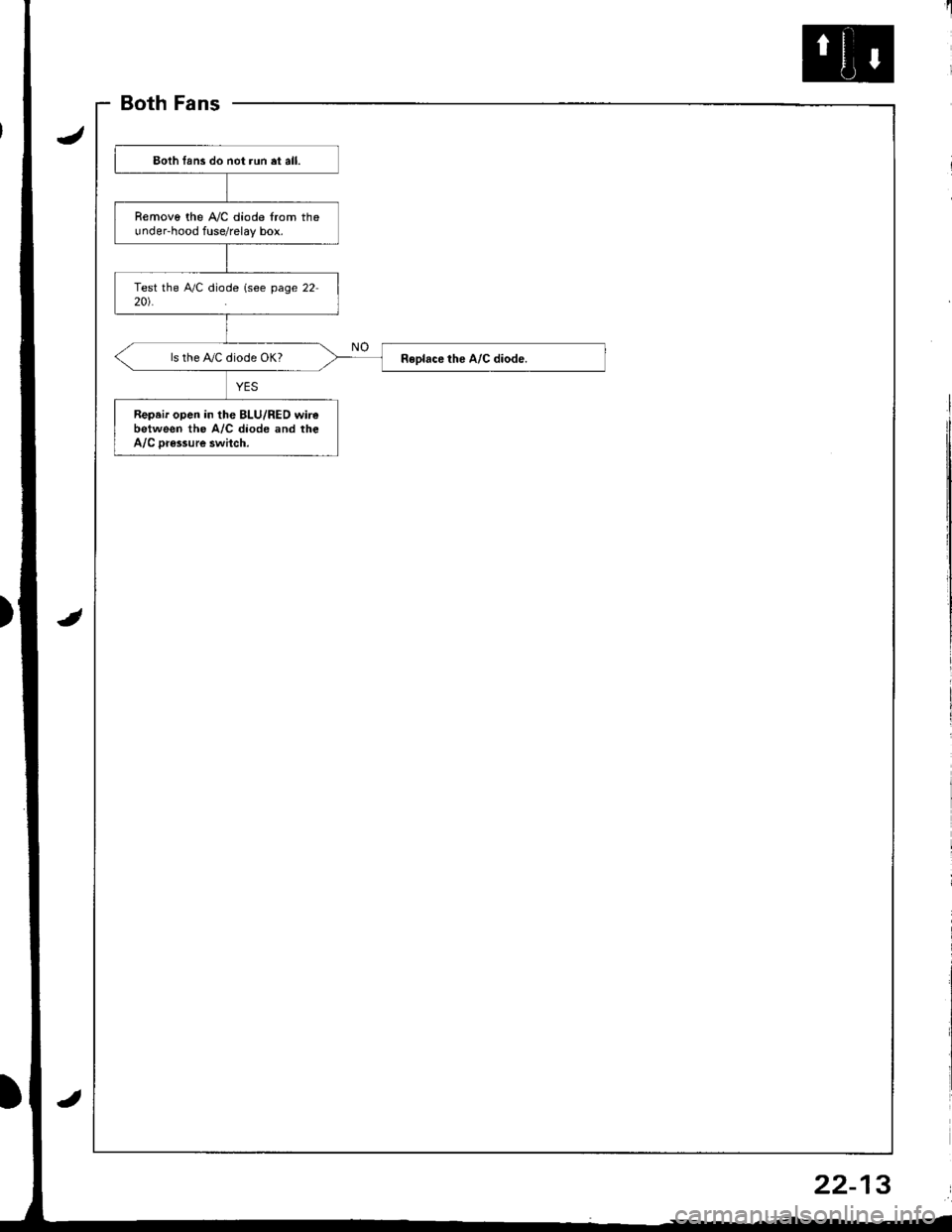
BothFans
)
Eoth lans do not run et all.
Removo the A,/C diode from theunder-hood fuse/relay box.
ls the IVC diode OK?
Repeir open in the BLU/RED wirebetween the A/C diode and theA/C Dr€ssure swhch.
22-13
Page 1032 of 1681
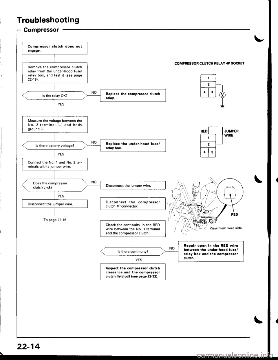
Troubleshooting
- Compressor
Remove the compressor clutchrelay trom the unde.hood tuse/relay box, and test it {see page
22-19t.
Measure the voltage beNveen theNo.2 terminal (+) and bodyground (-).
ls there battery voltage?
Connect the No. 1 and No. 2 terminals with a jumper wire.
Discon nect the compressorclutch 1P conoector.
Check lor continuity in the REDwire betlveen the No. 1 terminaland the compressor clutch.
Reprir open in tha BED wirabotwoon th6 undar-hood fusc/rolay box and lhs comp.osrorclutch.
In3p6ct th€ compre3sor clulchclear'nc€ and the comDressorcfutch ti€fd coil (se€ ptge22-321.
\-
COMPRESSOR CLUICH RELAY 'P SOCKET
JUMPERWIRE
\
To page 22-15
22-14
\
Page 1033 of 1681
![HONDA INTEGRA 1998 4.G Manual PDF COMPRESSOR CLUTCH RELAY P SOCIGT
I
,l
I
i:]
lll
i
ll
rl.
,i
lil
ECM CONNECTOR A (32PI
BLK/f,ED
WIRE SIDE OF FEMALE TERMINALS
ECM CONNECTOR C {31P}
BLU/RED
Connect the backprobe adapters to the stacki HONDA INTEGRA 1998 4.G Manual PDF COMPRESSOR CLUTCH RELAY P SOCIGT
I
,l
I
i:]
lll
i
ll
rl.
,i
lil
ECM CONNECTOR A (32PI
BLK/f,ED
WIRE SIDE OF FEMALE TERMINALS
ECM CONNECTOR C {31P}
BLU/RED
Connect the backprobe adapters to the stacki](/img/13/6069/w960_6069-1032.png)
COMPRESSOR CLUTCH RELAY 'P SOCIGT
I
,l
I
i:]
lll
i
ll
rl.
,i
lil
ECM CONNECTOR A (32PI
BLK/f,ED
WIRE SIDE OF FEMALE TERMINALS
ECM CONNECTOR C {31P}
BLU/RED
Connect the backprobe adapters to the stacking patch cords, and connect the cords to a mul-timeter. Using the wire insulation as a guide lor the contoured tip oI the backprobe adapter,gently slide the tip into the connector trom the wire side until it comes in contact with the ter-minalend ofthe wire {see section l1).
From page 22-14
*How to use the backprobe sets
Turn the ignition switch ON {11}.
i/leasure the voltage between theNo. 4 wire terminal (+) and bodyground {-).
Rcp.ir opon in tho BLK/YEL wirobetwsen tha undor.dash tu3a/rehy box rnd the undor.hoodfw6/i6lry box.
Turn tho ignition switch OFF, andreinstall the compressor clutch
Make suro the !y'C and heater fanswitches are OFF.
Turn the ignition switch ON {l1).
Using a *Backprobe Set (T/N
07SAZ - 001000A), measure th€voltage between the No. 17 termi-nal oI the ECM connocror A (32P)
and body ground wirh the ECMconnectors connected.
R.pair op.n in tho BLK/R€O wirobgtweon thg undor-hood fu!a/relly box 6nd th. ECM.
Using a *Backprobe Set (T/N
07SM - 001000A), moasure thevoltage betwe€n the No. 5 termi-nal of the ECM connector C (31P)
and body ground with the ECMconnectors connected.
Ropair op6n in tho BLU/RED wircbctwccn tho A/C diodc rnd theECM,
Subiiituto . known-good ECMrnd rochock. lt symptom/indicr-tion 90o3 away, .6placc the origi-n.l ECM.
WIRE SIOE OF FEMALE TERMINALS
22-15
Page 1035 of 1681
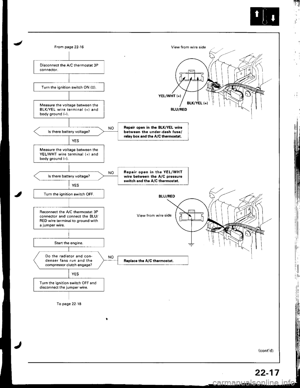
JView from wire sideFrom page 22-16
i,:,
il
rlt'
8LK/YEL l+)
YEL/WHT {+}
View from wire side
BLU/FED
(cont'd)
Turn the ignition switch ON {ll).
Measure the voltago between theBLK/YEL wire terminal (+) andbody ground (-).
Reprir opon in th€ BLK/YEL wir€batween the under-d.sh tuse/relay box rnd the A/C therm6tlt.
ls there battery vohageT
Moasure tho voltage between theYEL,A/VHT wire terminal (+) andbody ground (-).
Repair op6n in the YEL/WHTwire betwGen the A/C pressure
switch snd the A/C thermostat.ls th6re battery voltage?
Turn the ignition switch OFF.
Reconnect the A,/C thermostat 3Pconnector and connect the BLU/RED wire terminal to ground with
Do the radiator and con-denser fans run and thecompressor clutch engage?
Turn the ignition switch OFF anddisconnect the jumper wire.
To page 22'18
22-17
Page 1037 of 1681
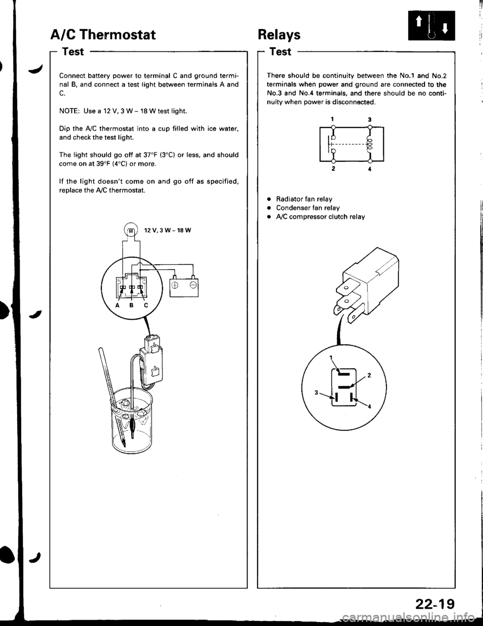
A/G Thermostat
I
I
a
a
a
t)
Connect battery power to terminal C and ground termi-
nal B, and connect a test light between terminals A and
c.
NOTE: Use a 12 V, 3 W- 18 Wtest light.
Dip the Ay'C thermostat into a cup filled with ice water,
and check the test light.
The light should go off at 37'F (3"C) or less. and should
come on at 39'F (4"C) or more.
lf the light doesn't come on and go off as specified,
replace the Ay'C thermostat.
12V,3W-18W
ABC
Relays
Test
There should be continuity between the No.1 and No.2
terminals when power and ground are connected to the
No.3 and No.4 terminals, and there should be no conti-
nuitv when Dower is disconnected.
Radiator fan relay
Condenser fan relay
Ay'C compressor clutch relay
,I I
ln P'Y )
.\-
l--l''-u...r.
22-19
Page 1058 of 1681
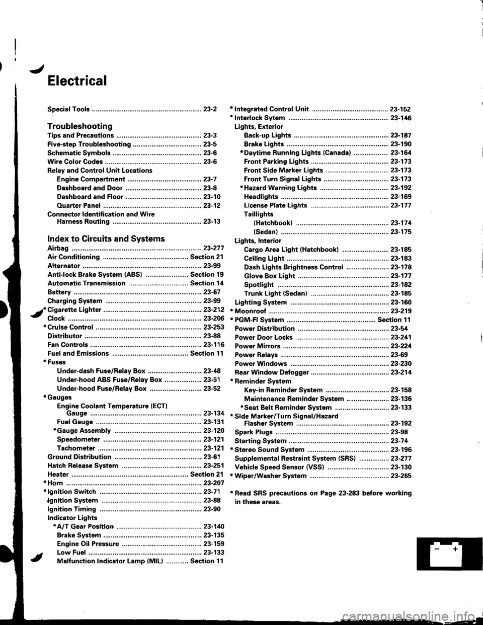
J
Electrical
Speciaf Toofs ..........................23-2
Troubleshooting
Tips 8nd Precautions .......................,..,.,.,.,.,......,..., 23-3
Five-step Troubleshooting ............,......,.,.,...,..,....., 23-5
Schsmatic Svmbols ...............23-6
Wire Color Code3 .. ................. 23-6
Relay and Control Unit Locations
Engine Compartment ......,.,.................,.,.,.,.,.,,,, 23-7
Dashboard and Door .........,...........,.....,.,....,.,.... 23-8
Dashboard and Floor ......................................... 23-10
Ouarter Pan€f .,,.,...,.,..,...,,,23-12
Connector ldontification and WireHarness Routing ......,.,......23-'13
Index to Circuits and Systems
Airbag
* Integrated Control Unit .....,.,.,.....23-152* Interlock Sytem .,...,.,...........,. 23.146
Lights, Exterior
Eack-up LighB ..................23.187
Brake Ligh$ ......................23-190*Daytime Running Lights (Canada) ................... 23"164
Front Parking Lights .......................................... 23-173
Front Side Marker Lights .................................. 23-173
Front Turn Signal Lights ..................-.......,...,.,. 23-173* Hazard Warning Lights ....................,........,....... 23-192
Headlights.....23-169
23-253 powerDistribution..................... 23-5/r
Air Conditioning.....,....... Soction 21
Alternator ..........,................... 23.99
iCigarette Lighter .........23-212
*Cruise Control
Distributor
'.'.,.'.'.,.'...,,,,.,''.'.,.',.'''.' 23.277
.............................. 23.88
................... 23-90lgnition Timing ......
Indicator Lights
Key-in Reminder System
Maintenance Reminder System*Seat Belt R€mindor System .,...........................* Side Marker/Turn Signal/HazardFlashcr Svstem .................23-192
Spark Plugs ............................23-98
Starting System .....................23-74* Stereo Sound System ...,......,..........,...,......,.,.,.,..,., 23-196
Supplemental Restraint System (SRS) ................ 23-277
Vshicle Speed Sensor (VSS) ................................. 23.130r Wiper/Washer System .........................................., 23-265
*Read SRS precautions on Psge 23-283 before working
in those areas,
23-154
23.136
23"133
Page 1060 of 1681
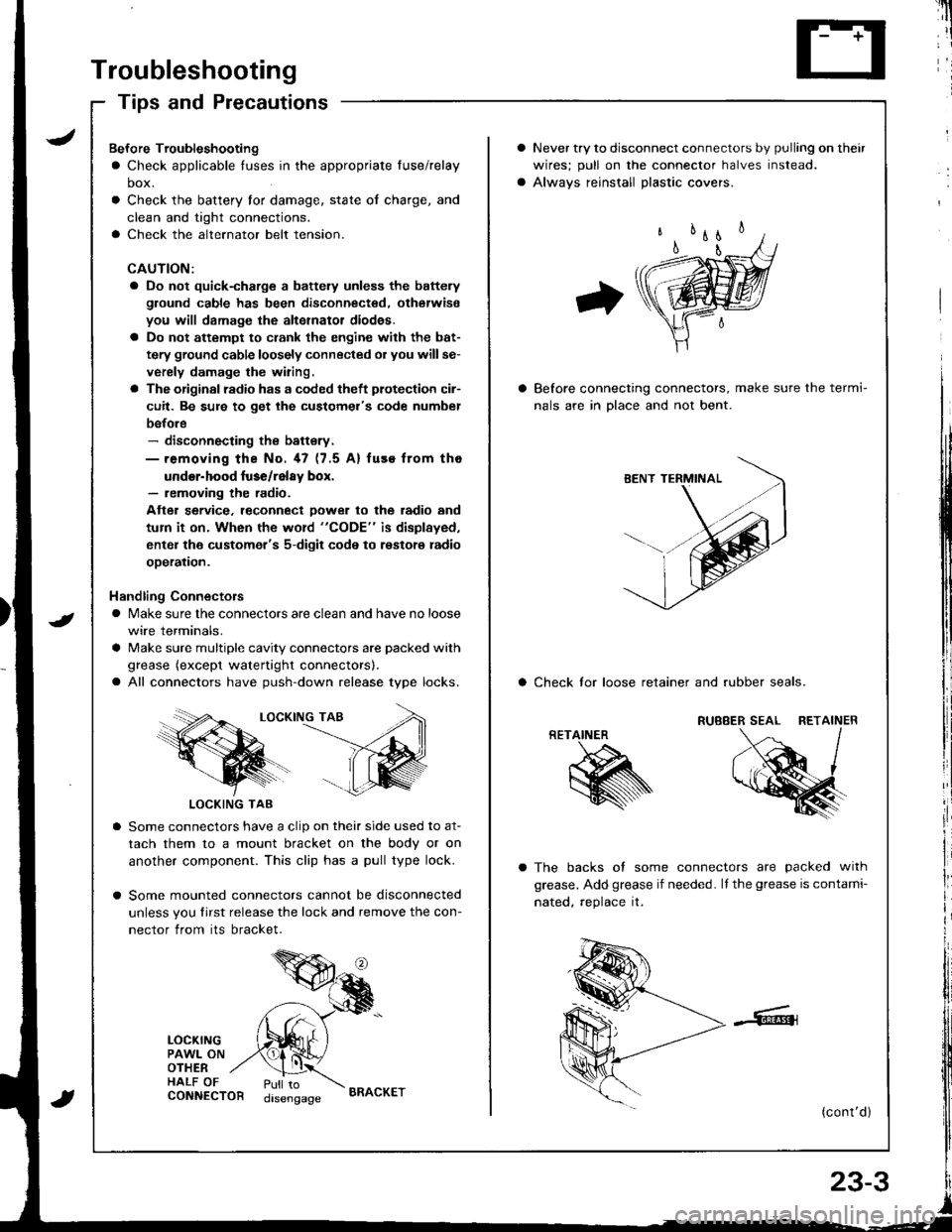
Troubleshooting
Tips and Precautions
Never try to disconnect connectors by pulling on their
wires; pull on lhe connector halves instead.
Alwavs reinstall Dlastic covers.
Before connecting connectors, make sure the termi-
nals are in Dlace and not bent.
a Check lor loose retainer and rubber seals.
The backs of some connectors are packed with
grease. Add grease if needed. lf the grease is contami-
nated, reolace it.
(cont'd )
RETAINER
K
Bef ore Troubleshooting
a Check applicable tuses in the appropriate fuse/relay
box.
Check the battery for damage, state of charge, and
clean and tight connections.
Check the alternator belt tension.
CAUTION:
a Do not quick-charge a battely unless the battery
ground cable has been disconnected. otherwise
you will damage the alternator diod€s.
a Do not attempt to crank the engine with the bat-
tery ground cable loosely connected or you willse-
verely damage the wiring.
a The originsl radio has a coded theft plotection cir-
cuit. Be sure to get the customel's code numbel
before- disconnecting the battsry.- removing the No. 47 (7.5 A) fuse from tho
under-hood luse/relay box.- removing the radio.
Atter service. leconnect Dower to the radio and
tum it on. When the word "CODE" is displayed,
enter the customer's 5-digit code to restore radio
ooeration.
Handling Connectors
a Make sure the connectors are clean and have no loose
wire terminals.
a Make sure multiple cavity connectors are packed with
grease (except watertight connectors).
a All connectors have push-down release type locks.
LOCKING TAB
LOCKING TAB
Some connectors have a clip on their side used to at-
tach them to a mount bracket on the body or on
another component. This clip has a pull type lock.
Some mounted connectors cannot be disconnected
unless you tirst release the lock and remove the con-
nector from its bracket.
LOCKINGPAWL ONOTHERHALF OFCONNECTORPull todisengageBRACKET
Page 1063 of 1681
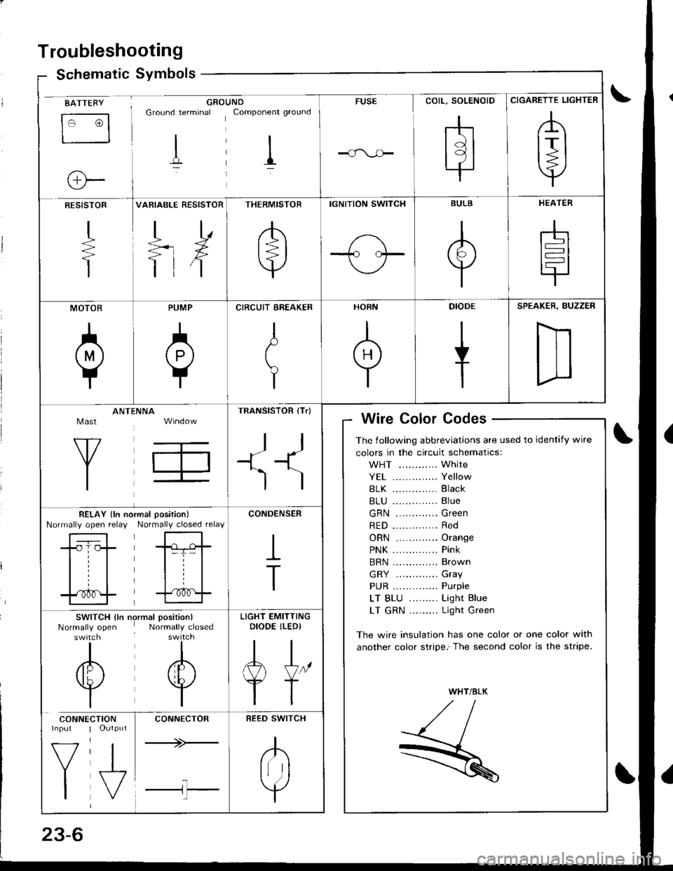
Troubleshooting
Schematic Symbolsym
BATTEBY
tr3
o-
GROUNDGround terminal Componenr ground
I il
FUSE
rhtdl
l9l.|
CIGARETTE LIGHTER
,A
lrl
Y
RESISTOR
+
T
VARIABLE RESISTOR
TD
=rX
ttf
THERMISTOR
/b'
t=l
v
IGNITION SWITCH
1-\-T- l.--
BULB
A
Y
HEATER
-h
t=l
tr
MOTOR
0
PUMP
A
Y
CIRCUIT EREAKER
I
t
Y
HORN
+
DIODE
+
SPEAKER, BUZZER
D
Mast
Y
ANTtiNNA
T,
TRANSISTOR (Tr)
ll
+1^'l
)
Wire Color Codes
The following abbreviations are used to identify wire
colors in the circuit schematics:
WHT ............ White
YE1 .............. Yellow
81K .............. Black
B1U .............. Blue
GRN ............. Green
RED .............. Red
ORN ............. Orange
PNK .............. Pink
BRN .............. Brown
GRY ............. Gray
PUR .............. Purple
LT BLU ......... Light Blue
LT GRN ......... Light Green
The wire insulation has one color or one color with
another color stripe.'The second color is the stripe.
WHT/BLK
,//,aI,//t- /
R
BELAY lln noNormally open relayrmal position)
Normally closed relay
-tr-f,-
l=T= |
til
trf
CONDENSER
I
T
SWITCH {ln nrNormally openswitch
I
/6\
v
I
)rmal position)Normally closed
I
A
w
I
LIGHT EMITTINGDIODE (LEDI
AJ"
YT
CONNE
V
I
CTIONOutput
J,
CONNECTOR
+>-
l-l'l
REED SWITCH
.K
Irr ]
Y
Page 1064 of 1681
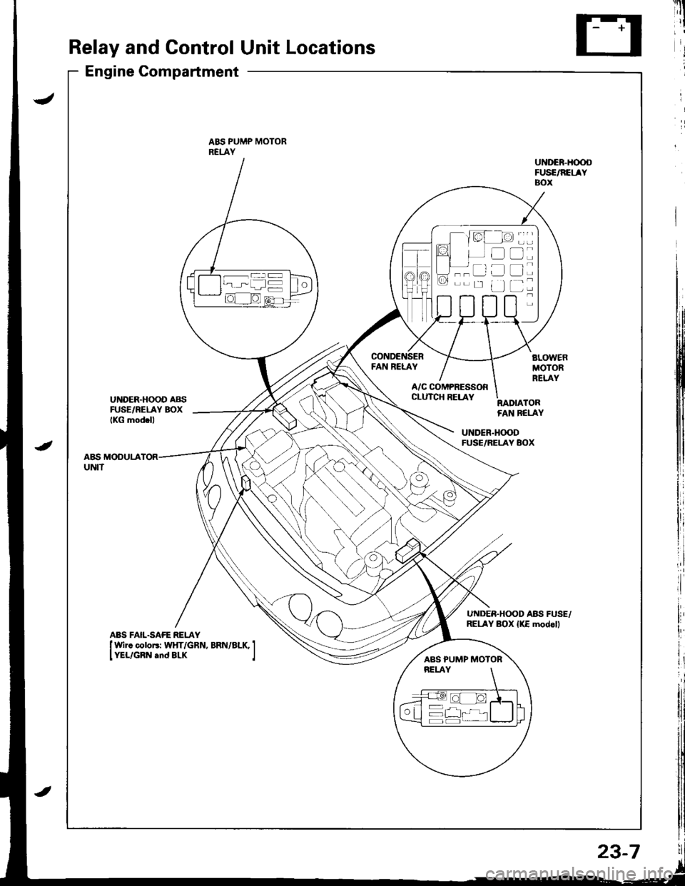
Relay and Control Unit Locations
Engine Compartment
ABS PUMP MOTORRELAY
FAN RELAY
UNDER.HOOD AB{iFUSE/RELAY BOXIKG mod.ll
A/C COMPRESSORCLUTCH RELAYRADIATORFAN BELAY
UNDER.H(X)DFUSE/RELAY BOX
A&S MODULAUNIT
UNDER.HOOD ABII FUSE,/RELAY BOX {KE modoll
----ar:l
--r: u
D
tr
L]
ABS PUMP MOTOR
23-7