HONDA INTEGRA 1998 4.G Repair Manual
INTEGRA 1998 4.G
HONDA
HONDA
https://www.carmanualsonline.info/img/13/6069/w960_6069-0.png
HONDA INTEGRA 1998 4.G Repair Manual
Page 993 of 1681
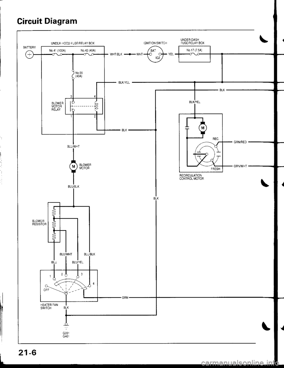
Circuit Diagram
R€CIRCULATIONcoNTROt MOTOR
UNDER HOOD FUSE/RELAY BOX
N0.41 (1004) N0.42 (40A)
,,\J.orr --'-- l,--
BtK
21-6
Page 998 of 1681
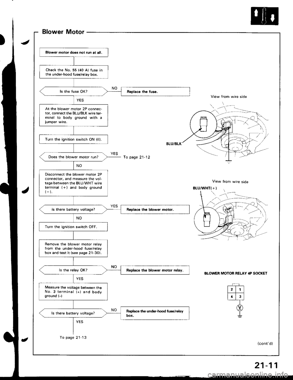
Blower Motor
View from wire side
View from wire slde
BLOWER MOTOR RELAY IP SOCKET
Blower motoa does not aun at all.
check the No. 55 {40 A} fuse inthe undeFhood fuse/relay box.
At the blower motor 2P connec-tor, connecl the BLU/8LK wire terminal to body ground with a
iumper wire.
Turn the ignition switch ON {ll).
Does the blower motor run?
Disconnect the blower motor 2Pconnector, and measure the vol-tage between the BLU/vVHT wireterminal (+) and body ground(-).
ls there battery vokagel
Turn the ignition switch OFF.
Rernove the blower motor relayfrom the under-hood fuse/relaybox and test it (see page 2l-30).
Roplsco tho blower motor .olsy.
Measure the voltage between thoNo. 3 terminal (+) and bodyground (-)
ls there battery voltage?
To page 21- 12
To page 21 13
rD
(cont'd)
Page 1000 of 1681
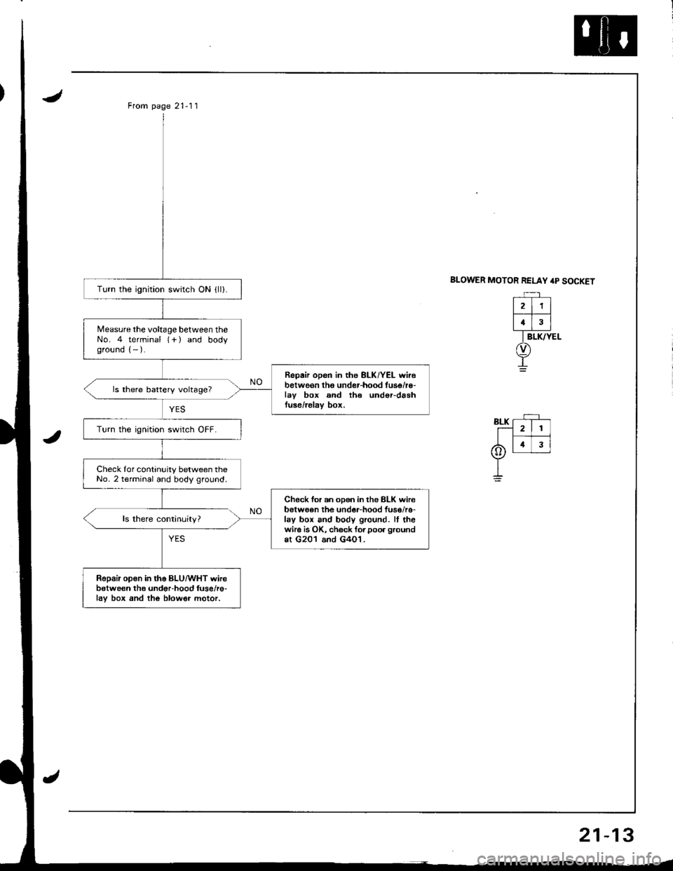
From page 21-11
BLOWER MOTOR RELAY /rp SOCKETTurn the ignition switch ON {ll).
Measure the voltage between theNo. 4 terminal (-f ) and bodyground (- ).
Repair open in the BLK/YEL wirebetweon tho under-hood tuse/r€-lav box and th€ und€r-drshtuse/relav box.
ls there battery voltage?
Turn the ignition swrtch OFF.
Check for continuity between theNo. 2 terminal and body ground.
Check for an oDen in the BLK wir€belween the undor-hood fuso/re-lay box and body ground. It thewire is OK, check forpoor groundat G201 and G4O1.
Ropair open in the BLU/WHT wirebetween the undor-hood fuse/re-lav box and the blow€r motor.
21
4
Page 1017 of 1681
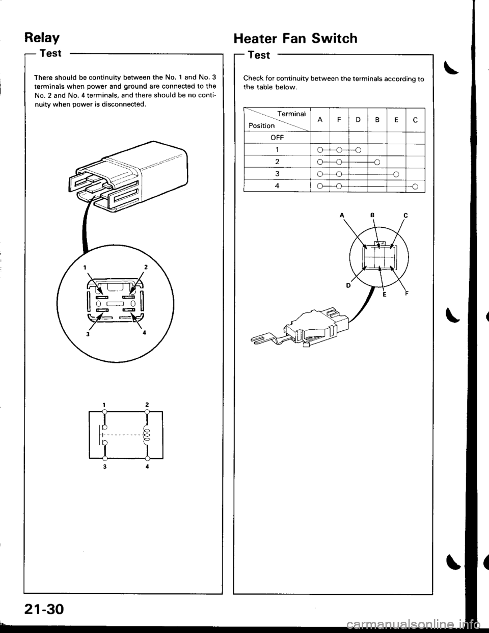
Relay
Test
There should be continuity between the No, I and No.3
terminals when power and ground are connected to the
No. 2 and No, 4 terminals, and there should be no conti-
nuitv when 9ower is disconnected.
rl
I
tb
I
Heater Fan Switch
Test
Check for continuity between the terminals according to
the table below.
Terminal
PositionFDBEc
OFF
o-o
2o--o
3o-o
G_o
21-30
Page 1022 of 1681
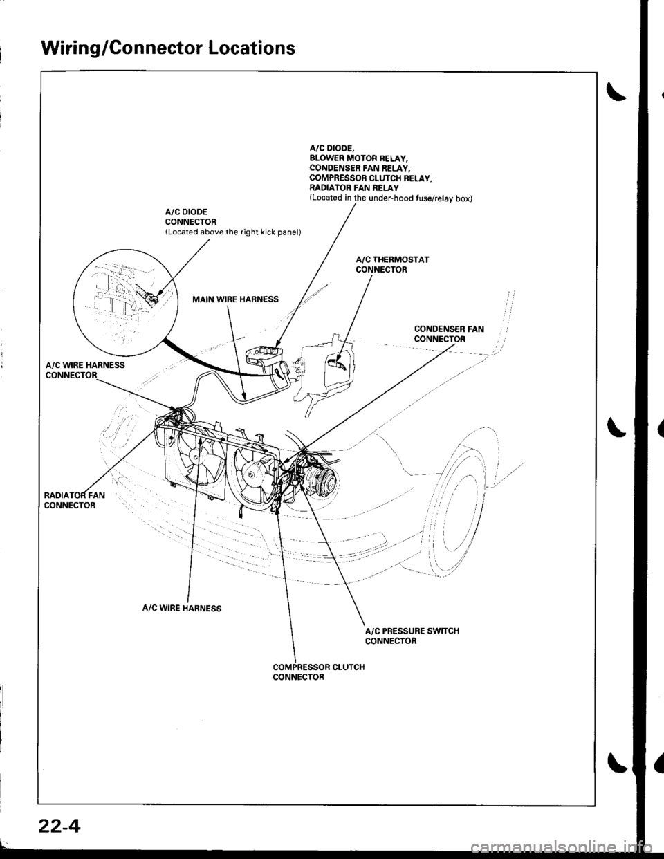
Wiring/Connector Locations
A/C DIODE.BLOWER MOTOR BELAY,CONOENSER FAN RELAY.COMPRESSOR CLUTCH RELAY,RADIATOR FAN REI-AY(Located in the under-hood tuse/relay box)
A/C DIODECONNECTORlLocated above the right kick panel)
MAIN WIBE HARNESS
A/C WINE HARNESS
A/C WIRE HARNESS
A/C PRESSURE SWITCHCONNECTOR
CLUTCHCONNECTOR
22-4
Page 1023 of 1681
Circuit Diagram
CONDENSERFANRELAY
!
BTKFED FEO
II
VIecu1xzrccl IT(l
tql
i.tli*, Tf7 r-
IBIU/RED
I-1
8LU/REO
.*.. *(if ) PRESSUFE
Y SWTCH
YEL/N4]T
lvcDIODE
- BLUiRED
I ,,,,^,-.,
IY
r.-'-"'-G8N
I,**',
Y ES:1i+31'
I
ts$'fts.,1
I
I
IBLK
I
G101
BLI(BED
I
I
I
,^r^r", IFANMoToRY
I
I
I
I8LK
T
G201G401
V
IBLU€LK
f7
IBLU/Y€L
V
IBLUMHT
V
IBLU
BLU/RED BLK,YEI
"fti.. i,, )
BLK
I
G151
Page 1025 of 1681
J
Troubleshooting
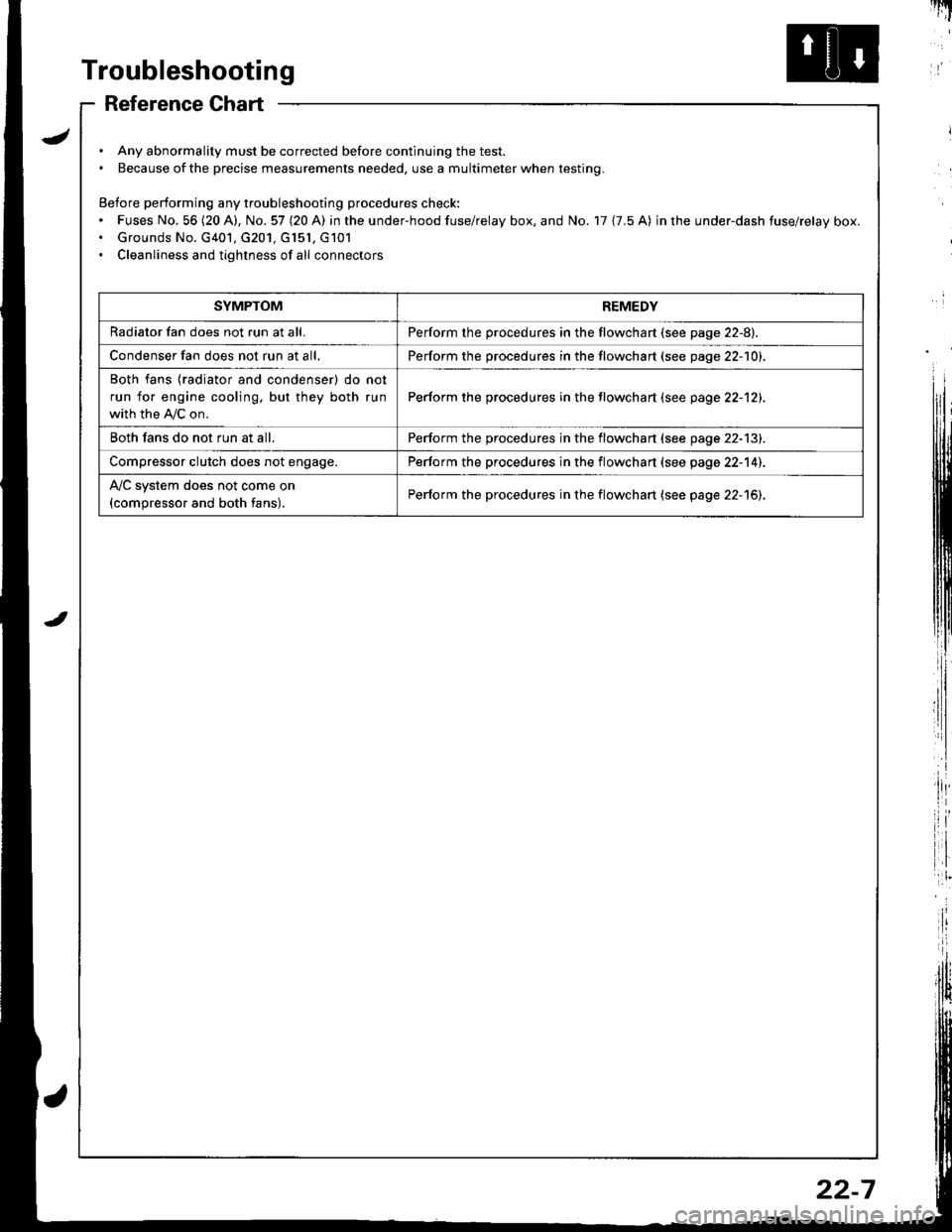
Reference Chart
. Any abnormality must be corrected before continuing the test.. Because of the precise measurements needed, use a multimeter when testing.
Before performing any troubleshooting procedures check:. Fuses No, 56 (20 A), No. 57 (20 A) in the under-hood fuse/relay box, and No. 17 {7.5 A) in rhe under-dash fuse/relay box.. Grounds No. G401, G201, G151, G101. Cleanliness and tightness of all connectors
I'IT
I
I
SYMPTOMREMEDY
Radiator fan does not run at all.Perform the procedures in the flowchart {see page 22-8).
Condenser fan does not run at all,Perform the procedures in the flowchart (see page 22-1O1.
Both fans {radiator and condenser) do not
run for engine cooling, but they both run
with the IVC on.
Perform the procedures in the tlowchart (see page 22-12).
Both fans do not run at all.Perform the procedures in the flowchart (see page 22-13).
Compressor clutch does not engage.Perform the procedures in the flowchart (see page 22-14).
l'lc system does not come on
{compressor and both fans).Perform the procedures in the flowchart (see page 22-15).
22-7
Page 1026 of 1681
Troubleshooting
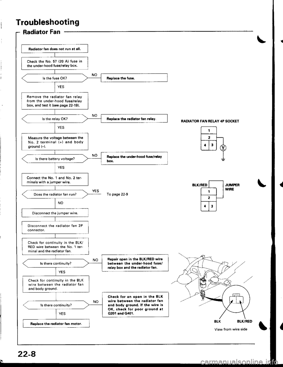
Radiator Fan
RADIATOR FAN RELAY 4P SOCKET
El2F-lt--T-- |
ujj I
I
",-*rrro [--l .u^rrrr
E lw'RE
l2-
trI
\
\
8LK BLK/RED
View from wire side\
Radiator lan does not run at all.
Chock the No. 57 (20 A) fuse in
the undeFhood fuse/relay box.
Remove the radiator tan relayfrom the under-hood fuse/rolaybox, and test it (see page 22-19).
Measuro the voltag€ betwogn theNo.2 terminal (+) and bodyground (-).
ls there battery voltage?
Connect the No. 1 and No. 2 ter-minals with a jumper wire.
Does the radiator fan run?
Check for continuity in the BLK/RED wire between the No. 1 ter-minal and the radiator fan.
Repair open in tho BLK/RED wir6b6twaon the undor-hood fuso/r6l6v box and the radirtorf6n.ls there continuity?
Check Ior continuity in the BLKwire between the radiator lanand body ground.
Chock for.n opon in tho BLKwiro botween tho .adiator fanand body ground, It tho wire i3OK, check for poor ground rtG201 and G401.
ls there continuity?
Roolace the radiator tan motor.
10 page 22-9
22-8
Page 1027 of 1681
From page 22 8
RADIATORFAN RELAY
l-'--l
| 2 |
[T;]
I BrK/YEt
o)
I
RELAY 4P SOCKET
Disconnect the,umper wire andturn the ignition switch ON (II).
Measure the voltage between theNo. 4 terminal (+i and bodyground ( ).
Ropair op€n in the GRN wire be-tween the undor-hood Iuse/.elay box and the A/C diode.
ls there battery voltage?
Repair open in the BLK/YEL wirebotwean the under-hood tuse/relay box snd the under-daahfuso/relay box,
22-9
Page 1028 of 1681
Troubleshooting
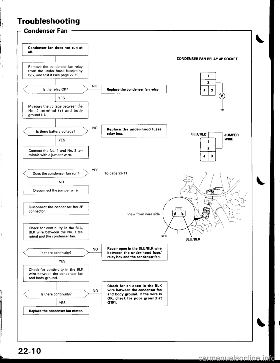
Condenser Fan
0
Remove the condenser fan relayfrom the underhood fuse/relaybox, and test it (see page 22-19).
Roplaco the condenser fan rgley.
Measure the voltage between tlieNo. 2 terminal {+) and bodyground (-).
Connect the No. 1 and No. 2 ter-minals with a jumper wire.
Does the condenser fan run?
Check for continuity in the BLU/BLK wire between lhe No. 1 ter'minal and the condenser fan.
Ropair open in the BLU/BLK wir.between tho undor-hood fu3e/relay box and lh€ condan3er fan.ls there continuity?
Check for continuity in the BLKwire between the condenser fanand body ground.
Check tor an ooen in the BLKwir6 betwoen the condan3er fanand body ground. lf the wire isOK, check for poor ground atGr51.
ReDlace the condenser fan motor,
CONDENSER FAN RELAY 4P S(rcKET
ls the relay OK?
YES
RoDlace the undor-hood tuse/r€lay box.JUMPERWIRE
To page 22 11
',,/-i, /
cr-i,
View from wire sideq
BI-U/BLX
22-
![HONDA INTEGRA 1998 4.G Repair Manual Circuit Diagram
CONDENSERFANRELAY
!
BTKFED FEO
II
VIecu1xzrccl IT(l
tql
i.tli*, Tf7 r-
IBIU/RED
I-1
8LU/REO
.*.. *(if ) PRESSUFE
Y SWTCH
YEL/N4]T
lvcDIODE
- BLUiRED
I ,,,,^,-.,
IY
r.--"-G8N
I,**,
Y HONDA INTEGRA 1998 4.G Repair Manual Circuit Diagram
CONDENSERFANRELAY
!
BTKFED FEO
II
VIecu1xzrccl IT(l
tql
i.tli*, Tf7 r-
IBIU/RED
I-1
8LU/REO
.*.. *(if ) PRESSUFE
Y SWTCH
YEL/N4]T
lvcDIODE
- BLUiRED
I ,,,,^,-.,
IY
r.--"-G8N
I,**,
Y](/img/13/6069/w960_6069-1022.png)


![HONDA INTEGRA 1998 4.G Repair Manual From page 22 8
RADIATORFAN RELAY
l---l
| 2 |
[T;]
I BrK/YEt
o)
I
RELAY 4P SOCKET
Disconnect the,umper wire andturn the ignition switch ON (II).
Measure the voltage between theNo. 4 terminal (+i and b HONDA INTEGRA 1998 4.G Repair Manual From page 22 8
RADIATORFAN RELAY
l---l
| 2 |
[T;]
I BrK/YEt
o)
I
RELAY 4P SOCKET
Disconnect the,umper wire andturn the ignition switch ON (II).
Measure the voltage between theNo. 4 terminal (+i and b](/img/13/6069/w960_6069-1026.png)
