relay HONDA INTEGRA 1998 4.G Repair Manual
[x] Cancel search | Manufacturer: HONDA, Model Year: 1998, Model line: INTEGRA, Model: HONDA INTEGRA 1998 4.GPages: 1681, PDF Size: 54.22 MB
Page 807 of 1681
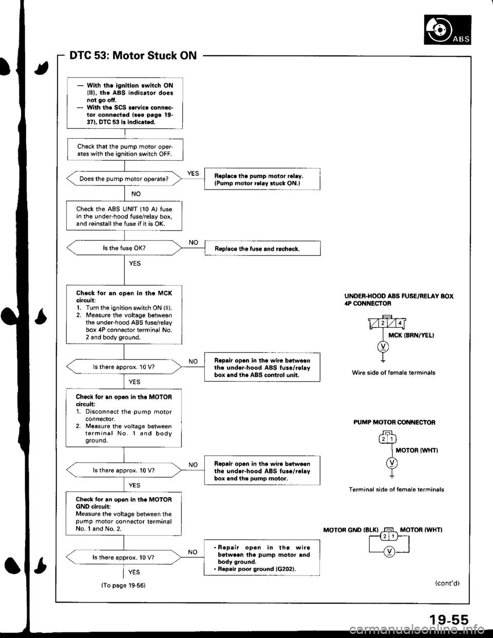
DTC 53: Motor Stuck ON
LI
UNDER.HOOD ABS FUSE/RELAY BOXlP@ NECTOR
MCK IBRN/YELI
Wire side oI female terminals
PUMP MOTOR CONI{ECTOR
.F\t2 1lY
IMoroR twHrl
(v)
Y
Terminal side of temale terminals
MOTOR (WHT}
- With th. ignition switch ONlll), tho ABS indicator doesnot go oft.- With th. SCS scrvico connec-lor connoctod |roo prgo 19-371. DTC 5:l i! indicrted.
Chock that the pump motor opeFates with the ignition switch OFF.
R.phce the pump motor rolay.lPump motor ralay ltuck ON.)Does the pump motor oporate?
Check the ABS UNIT (10 A) fusein tho under-hood fuse/relay box,and reinstallthe fuse if it is OK.
Replace tho fuso and rcchock,
Chock tor an opcn in thc MCKcircuit:1. Turn the ignition switch ON (lll.
2. Measure the voltage betvveenthe under-hood ABS luse/relaybox 4P connector terminal No.2 and body ground.
R.psir opan in thc wiro botwoonthc undar-hood ABS tuso/rolaybox .nd lho ABS contJol unh.
ls there approx. 10 V?
Chock tor .n opon in tho MOIORcircuit:1. Disconnect the pump motorconnector,2. Measure the voltage botweenterminal No. l and bodyground.
Ropair open in the wire bstwsenth6 undor-hood ABS fu3e/rclevbox rnd the pump molor.
ls there approx. 10 V?
Check tor tn opor in the MOTORGND circuii:Measure the voltage between thepumo motor connector tetminalNo. 1 and No.2.
.Repeir open in tho wirobotwaan the pump motor andbody ground.. Rep.ir poor ground (G202).
ls there approx. 10 V?
(To page 19-56)
MOTON GND
(cont'd)
Page 808 of 1681
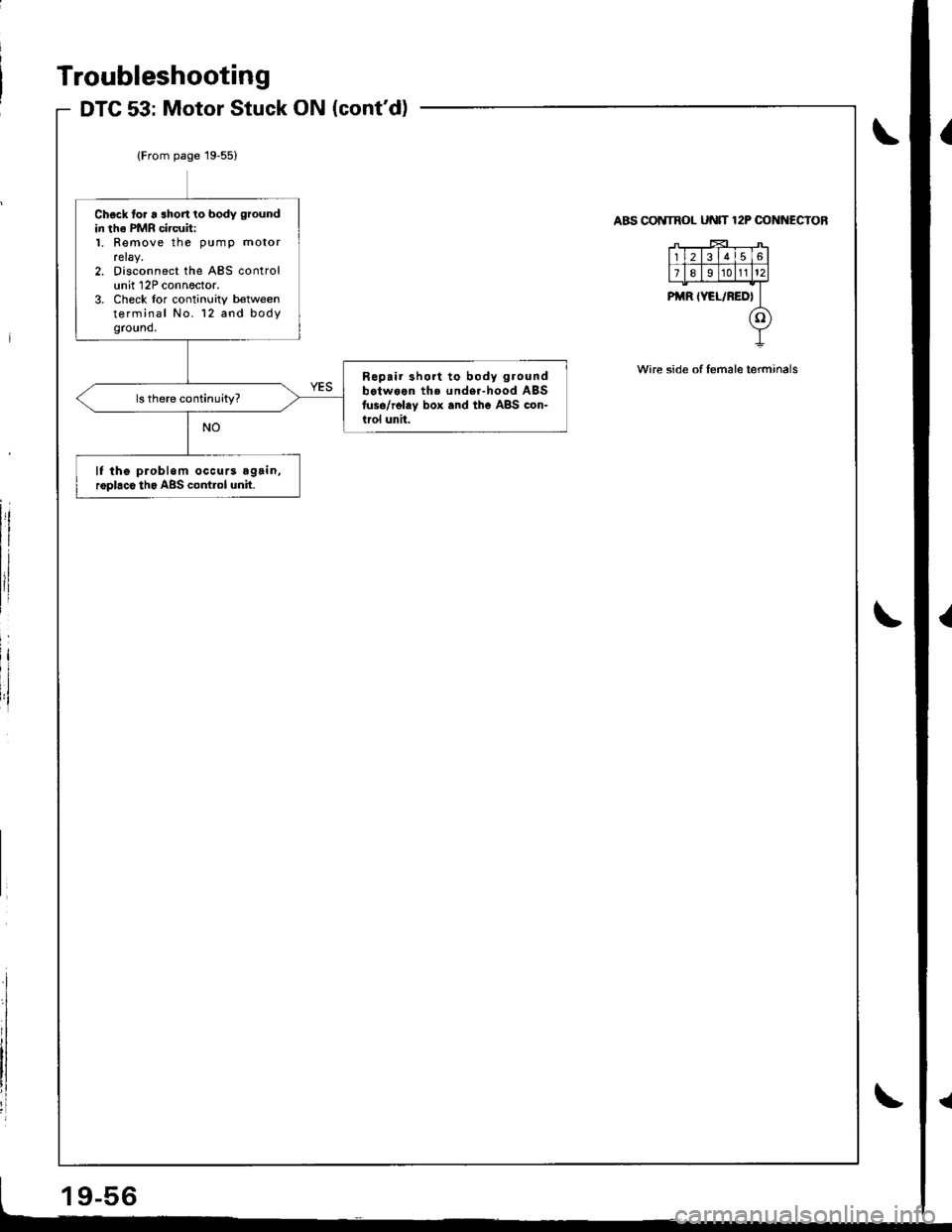
Troubleshooting
DTC 53: Motor Stuck ON (cont'd)
\{
i
(From page 19-55)
Chock to. r shon to body ground
in tho PMR circuit:L Remove the pump motorrelay.2. Disconnect the ABS controlunit 12P conn6ctor.3. Check lor continuity b€tweenterminal No. 12 and bodyground.
R6pair 3hort to body ground
b.tween th6 under-hood ABSfuso/rolay box .nd the ABS con-irol unit.
lf tho problom occurs again,roplaco tho ABS contlol unh.
COIVTROL UN]T I2P OONI{ECTOR
/Lr-r-F-,--T+t1t2t3l4t516l
FT;sTrrFoFiFZ._T
PMR tYEL/RED[
(o)
Y
wire side of lemale terminals
9-56
Page 809 of 1681
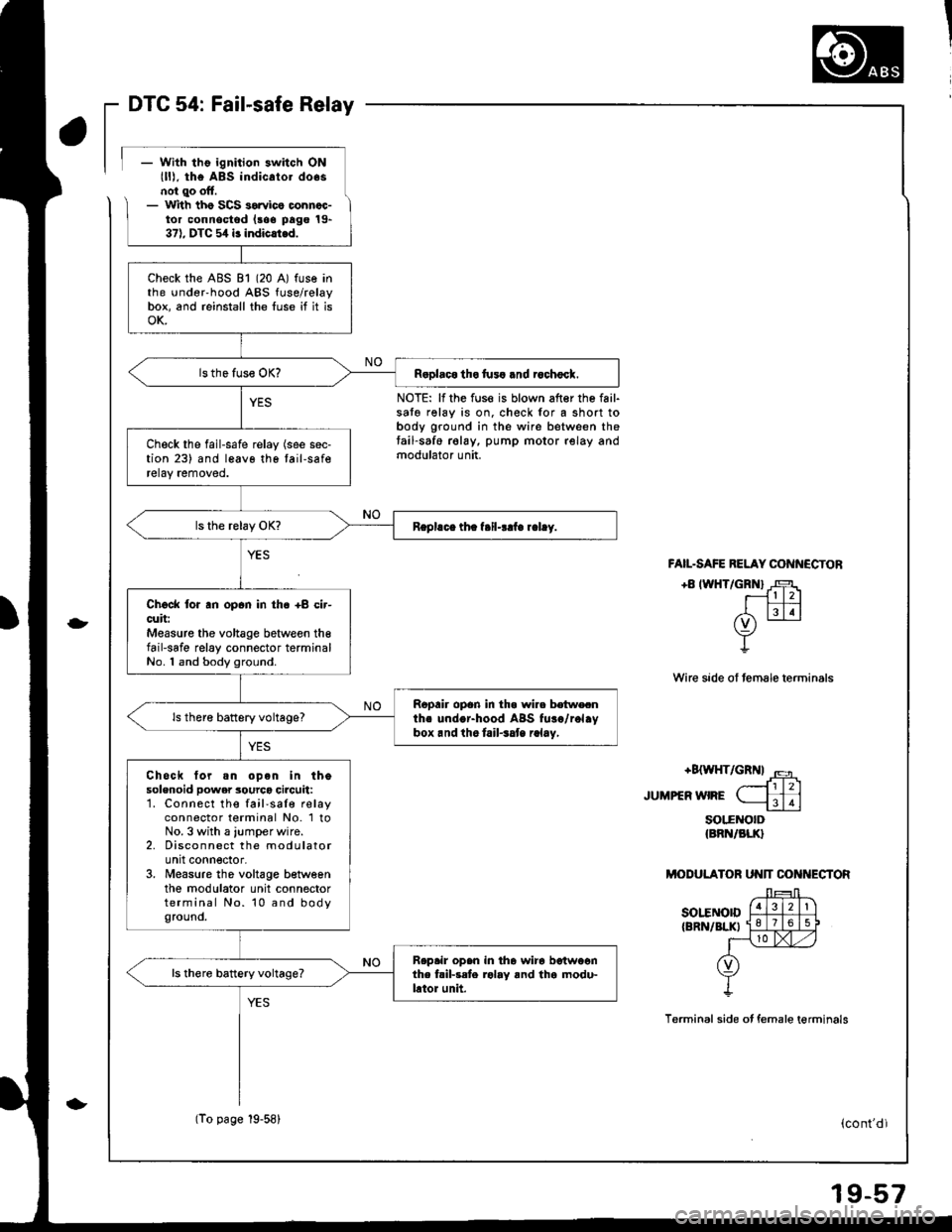
DTC 54: Fail-safe Relay
- With tho ignition switch ONlll), the ABs indicato. do.snol qo oft.- lr
ith tho SCS sorvico oonncc-tor connoctod (aoe pago 19-37). DTC 5,1 i3 indicli.d.
NOTE: lf the fuse is blown after the fail-sato relay is on. check for a short tobody ground in the wire between thetail-saf6 relay, pump motor relay andmodulator unit.
-
FAIL.SAFE RELAY CONN€CTON
+8 IWHT/GRNI J-F1r- l l2l
EIN(v) -
Y
Wire sade ol female terminals
+8{WHT/GRN| '.5
JUMPEFWIFE ( ffi-----1113
soltNorD{BRN/BLK}
MODULATOR UN]T CON ECTOR
sot"ENorD{BRN/BLKI
Terminal side ot female terminals
Check the ABS 81 (20 A) fuse inthe under'hood ABS fuse/relaybox, and reinstall the luse if it isoK.
R.olaco tho fu3! .nd rochocl.
Check the fail-safe relay (see sec-tion 23) and leavo tho tail-saferetay removed.
Chock lor an opan in th6 +8 cir-cuit:Measure the voltage between th€fail-safe relay connector terminalNo. 1 and body ground.
Ropair opon in tha wire botwecnths undor-hood ABS fuso/rol.ybox.nd ihe tail.3at r.lay,
ls there battery voltage?
Chock tor.n op6n in thesolenoid power 3ourco circuit:1. Connect the fail'saIe relayconnector terminal No. 1 toNo. 3 with a jumper wire.2. Disconnect the modulatorunit connector,3. Measure tho voltage betweenthe modulator unit connectorterminal No. 10 and bodyground.
Rep.ir open in tha wira betwoonthe fril-rete rolay and tha modu-lator unit.
ls there battery voltage?
(To page 19-58)(cont'dl
Page 810 of 1681
![HONDA INTEGRA 1998 4.G Repair Manual Troubleshooting
DTG 54: Fail-safe Relay (contd)
MODULATOB UN]T CONI{ESTOR
sor5NorD f;Fl-�Ti)
rBRN/BLn 1qll9l-1i
l-\!xtz)
O)
Y
Terminal side of female terminals
ll
ABS CONTROL UNIT 22P CONITECTOR
Wir HONDA INTEGRA 1998 4.G Repair Manual Troubleshooting
DTG 54: Fail-safe Relay (contd)
MODULATOB UN]T CONI{ESTOR
sor5NorD f;Fl-�Ti)
rBRN/BLn 1qll9l-1i
l-\!xtz)
O)
Y
Terminal side of female terminals
ll
ABS CONTROL UNIT 22P CONITECTOR
Wir](/img/13/6069/w960_6069-809.png)
Troubleshooting
DTG 54: Fail-safe Relay (cont'd)
MODULATOB UN]T CONI{ESTOR
sor5NorD f;Fl-'�Ti)
rBRN/BLn 1qll9l-1i
l-\!xtz)
O)
Y
Terminal side of female terminals
ll
ABS CONTROL UNIT 22P CONITECTOR
Wire side ol female terminals
FAIL.SAFE RELAY CONI{ECTOR
Wire side of temale terminals
ABS CONTROL U[{IT 22P OONNECTOR
{From page'19-57)
Ch6ck tor a shon to powor in thesolenoid powgr source circuit:1. Remove the iumper wire fromthe fail-sale relay connector.2. Measure the voltage betweenthe mod{rlator unit connectortorminal No. 10 and bodyground.
Repair shon to powor in tho wire
between tho ftil{at rolaY, mod-uletor unit and tho undar-hoodABS fu3e/relay box.
ls there battery vokage?
Check tor a $hort to Power in theFSR circuh:1. Disconnect the ABS controlunit 22P connector.2. Turn the ignition switch ON (ll).
3. Measure the voltage betweenthe terminal No.21 and bodyground.
Repair short to powor in tha wircbetwoon the ABS control unit
rnd tho tail{sla rehy.ls there battery voltage?
Chgck for a 3hort to body ground
in th6 FSR circuit:Check for continuiw between theABS control unit 22P connectorterminal No. 21 and body ground.
Rapair short to bodv ground inthe wir. betwoon the ABS con-trol unit andthe f.il-sdo rolay.
Check for an open in the FSRGND circuit:Check lor continuity betlveen thefail safe relay connector terminalNo. 4 and body ground.
Repeir op.n in ths wire betweentho tail-sate.olay and bodyground.
Check for sn opan in the FSR cir-cuh:1. Installthe lail-sale relay.2. Check for continuity betweenthe ABS control unit 22P connector terminal No, 21 andbody ground.
Repair opgn in the wire betwoonthe ABS control unit snd tho fail-safe r6lay.ls there continuity?
lf the probl6m occurs.gain,roolaco the ABS control unit.
Wire side of female terminals
Page 893 of 1681
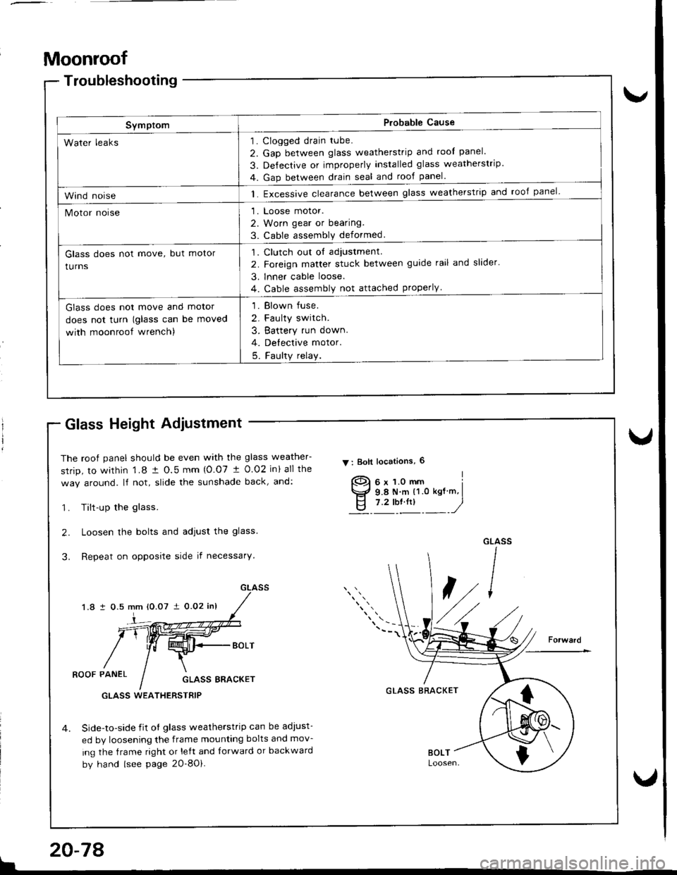
Moonroof
Troubleshooting
SymptomP.obable Cause
Clogged drain tube.
Gap between glass weatherstrip and roof panel
De{ectrve or improperly Installed glass weatherstrip
Gap between drain seal and rool panel.
Excessive clearance between glass weatherstrip and roof panel-
Loose motor.
Worn gear or bearing.
Cable assemblv deformed.
1
2
3
4
1
2
3
1.
Water leaks
Wind noise
Motor noise
Glass does not move, but motor
turns
Clutch out ol adiustment.
Foreign matter stuck between guide rail and slider'
lnner cable loose.
Cable assembly not attached properly
,l
2
3
4
Glass does not move and motor
does not turn (glass can be moved
with moonroof wrench)
1. Blown fuse.
2. Faulty switch.
3. Battery run down.
4. Delective motor.
5. Faulty relay.
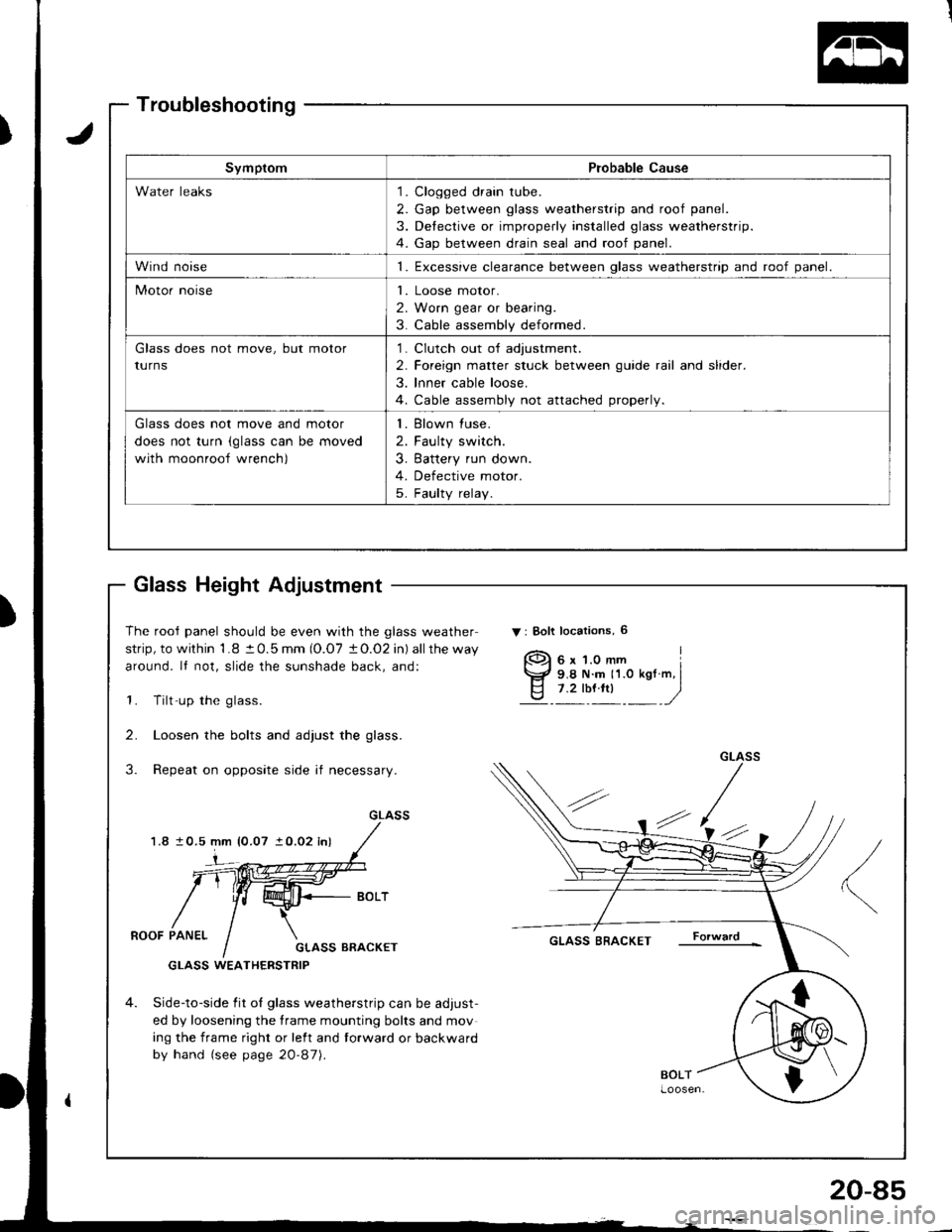
Glass Height Adiustment
The roof panel should be even with the glass weather-
srrip, to within 1.8 t O.5 mm {O.07 t 0.02 in} all the
way around. lf not, slide the sunshade back, and:
1. Tilt-up the glass.
2. Loosen the bolts and adjust the glass.
3. Repeat on opposite side if necessary.
1.8 i 0.5 mm 10.07 i 0.02 inl
V : Boll locations, 6
]-
ROOF PANELGLASS BRACKET
Side-to-side iit of glass weatherstrip can be adJust-
ed by loosening the frame mounting bolts and mov-
ing the frame right or left and {orward or backward
by hand (see page 2O-8Oi.
GLASS BRACKETGLASS WEATHERSTRIP
{
$
I
!
20-78
Page 900 of 1681
)
Troubleshooting
Glass Height Adjustment
The rooJ panel should be even with the glass weather
strip, to within 1.8 t 0.5 mm (O.O7 tO.O2 in) allthe way
around. It not, slide the sunshade back, and:
1. Tilt-up the glass.
2. Loosen the bolts and adjust the glass.
3. Repeat on opposite side if necessary.
1.810.5 mm {0.07 } 0.02 inl
Gr_ASS
4-(.'
ROOF PANELGLASS BRACKET
GLASS WEATHERSTRIP
4. Side-to-side fit oI glass weatherstrip can be adjust-
ed by loosening the frame mounting bolts and mov
ing the frame right or left and forward or backward
by hand (see page 20-87).
GLASS BRACKET
SymptomProbable Cause
Water leaks1. Clogged drain tube.
2. Gap between glass weatherstrip and roof panel.
3. Detective or improperly installed glass weatherstrip.
4. Gap between drain seal and roof panel.
Wind noise1. Excessive clearance between qlass weatherstriD and roof oanel.
Motor noiseI
2
3
Loose motor.
Worn gear or bearing.
Cable assembly deformed.
Glass does not move, but motor
turnS
1
2
3
Clutch out of adjustment.
Foreign matter stuck between guide rail and slider.
lnner cable loose.
Cable assembly not attached properly.
Glass does not move and motor
does not turn (glass can be moved
with moonroof wrench)
I
2
3
Blown fuse.
Faulty switch.
Battery run down.
Defective motor.
Faulty relay.5
{
s
I
20-85
Page 949 of 1681
Dashboard
Component Removal/lnstallation (cont'dl
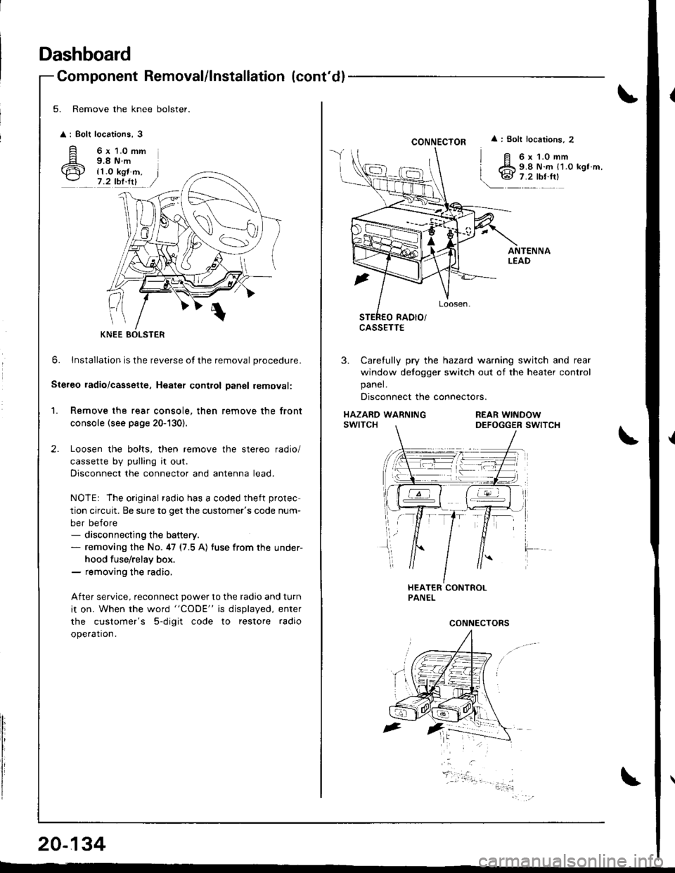
5. Remove the knee bolster.
: Bolt
A'ir
locations,3
6 x 1.0 mm9.8 N.m
{1.0 kgt m,7.2 tbf.fit
0
6. lnstallation is the reverse o{ the removal procedure.
Ste.eo ladio/cassette, Heatet contlol Danel removal:
1. Remove the rear console, then remove the front
console (see page 20-130).
Loosen the bolts, then remove the stereo radio/
cassette by pulling it out.
Disconnect the connector and antenna lead.
NOTEr The original radio has a coded theft protec-
tion circuit. Be sure to get the customer's code num-
ber before- disconnecting the battery.- removing the No. 47 (7.5 A) tuse from the under-
hood fuse/relay box.- removing the radio,
After service, reconnect power to the radio and turn
it on. When the word "CODE" is displayed, enter
the customer's 5-digit code to restore radio
ope.ation.
KNEE BOLSTER
20-134
CONNECTOR
CASSETTE
: Bolt locations, 2
6x1.0mm9.8 N.m {1.0 kgt m,
3. Carefully pry the hazard warning switch and rear
window detogger switch out of the heater control
panel.
Disconnect the connectors.
HAZARD WARNINGswtTcHREAR WINDOWDEFOGGER SWITCH
CONNECTORS
Page 953 of 1681
Dashboard
Replacement Precautions
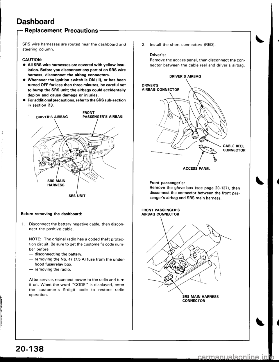
SRS wire harnesses are routed near the dashboard and
steenng column.
CAUTION:
a All SRS wire hsrnesses are covered wiih yellow insu-
lation. Before you disconnect any pan of an SRS wire
harness, disconnect the airbag conneclors.
a Whenever the ignition switch is ON (ll), or has been
tulned OFF for less than three minules, be careful not
to bump the SRS unit; the ai.bags could accidentally
deploy and cause damage or injuries.
a For additional precautions, refer lo the SRS sub-section
in section 23.
PASSENGER'S AIRBAG
Belore removing the dashboard:
1. Disconnect the battery negative cable, then discon-ne.r rhe n^.iriua.ahla
NOTEr The original radio has a coded thett protec,
tion circuit. Be sure to get the customer's code num
ber before- disconnecting the battery.- removing the No. 47 (7.5 A) fuse from the under-
hood tuse/relay box.- removing the radio.
After service, reconnect power to the radio and turn
it on. When the word "CODE" is displayed, enter
the customer's 5-digit code to restore radio
operation.
DRIVER'S AIRBAG
SRS UNIT
20-138
2.Install the short connectors (RED).
Driver's:
Remove the access panel, then disconnect the con-
nector between the cable reel and driver's airbag.
CABL€ REELCONNECTOR--_--._-_-----
Front passenger's:
Remove the glove box (see page 20-137), thendisconnect the connector between the front pas-
senger's airbag and SRS main harness.
FRONT PASSENGER'SAIRBAG CONNECTOR
SRS MAIN HARNESSCONNECTOR
ORIVER'S AIRBAG
Page 955 of 1681
Dashboard
6.
Replacement (cont'dl
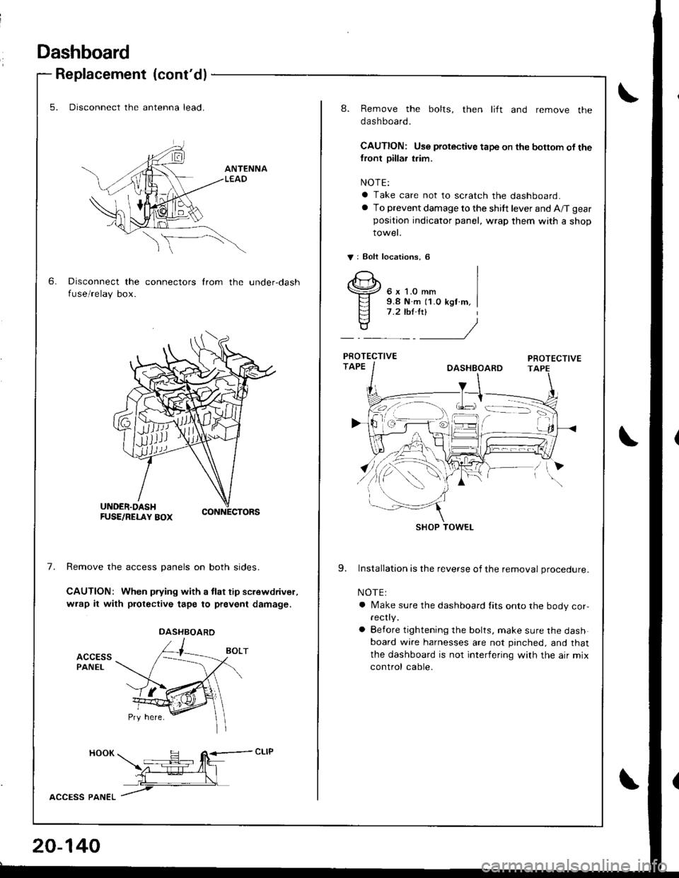
5. Disconnect the antenna lead.
Disconnect the connectors from the under-dash
fuse/relay box.
7.Remove the access panels on both sides.
CAUTION: When pfying with a tlat tip screwdrivel,
wrap it with protective tape to prevent damage.
ACCESSPANEL
HOOK H R<-- cLlP -- tfit\z-:E--4l_l
L__\L
lccPss pltlteL /
DASHBOARD
20-140
8. Remove the bolts, then lift and remove the
dashboard.
CAUTION: Use protective tape on the bottom of thefront pillar trim.
NOTE:
a Take care not to scratch the dashboard.
a To prevent damage to the shift lever and A/T gear
position indicator panel, wrap them with a shop
rowet.
V: Eolt localions, 6
6 x 1.0 mm9.8 N.m {1.0 kgf m,7 .2 ,hl.ltl
9. Installation is the reverse of the removal procedure.
NOTE:
a Make sure the dashboard fits onto the body cor,rec y.
a Before tightening the bolts, make sure the dashboard wire harnesses are not pinched, and that
the dashboard is not interfering with the air mix
control cable.
SHOP TOWEL
Page 988 of 1681
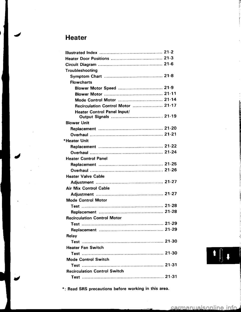
iii
i
I
J
Heater
fffustrated Index ............. ......'..21-2
Heater Door Positions '....'........ 21-3
Circuit Diagram ....................... 21-6
Troubleshooting
Symptom Chart ............. '.....21-8
Flowcharts
Blower Motor Speed ...............'......'........ 21 -9
Blower Motor ............'......21-11
Mode Controf Motor ............ ............'... "' 21 -14
Recirculation Control Motor ......'...... "'.,.,. 21 -1 7
Heater Control Panel Input/
Output Signals ...'.......... 21-19
Blower Unit
Replacement ........ '....... ',..,.. 21-2O
Overhaul ",',..21-21
*Heater Unit
Repf acement .....'.....'........'.. 21'22
Overhaul .......21-24
Heater Control Panel
Repfacement ....... '..... '......... 21-25
Overhaul .......21-26
Heater Valve Cable
Adjustment '.. 21'27
Air Mix Control Cable
Adiustment ... 21-27
Mode Control Motor
Test .............. ..................... 21'24
Repfacement ....................... 21-24
Recirculation Control Motor
Test .............. ..................... 21-29
Repf acement .........'........ " ". 21-29
Relay
Test .............. ..................... 21-3O
Heater Fan Switch
Test .............. ....................' 21-30
Mode Control Switch
Test .............' "'..............'... 21-31
Recirculation Control Switch
Test .............. ..................... 21-31
*: Read SRS precautions before working in this area.