light HONDA INTEGRA 1998 4.G Repair Manual
[x] Cancel search | Manufacturer: HONDA, Model Year: 1998, Model line: INTEGRA, Model: HONDA INTEGRA 1998 4.GPages: 1681, PDF Size: 54.22 MB
Page 661 of 1681
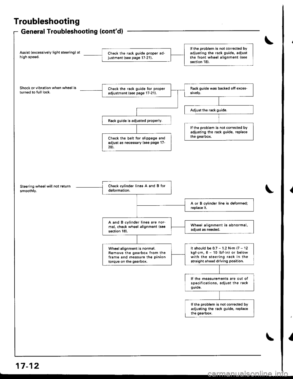
Troubleshooting
General Troubleshooting (cont'dl
Assist (excessively light steering) athigh speod.
Shock or vibration when wheel isturned to full lock.
Steering wheel will not return
smoothly.
a-, aa GrI r- tz
ll the problom is not correcled byadiusting the rack guide, adjustthe front wh66l alignment (see
s6ction 18).
Ch6ck th6 rack guide propgr ad-justment (see pago 17-21).
Check the rack guido lor proper
adjustment (see page 17-21).
Rack guid€ is adjusted properly.
lf the problem is not corrected byadjusting the rack guide, replscothe gearbox.Check the belt for slippage andadjust as nec€ssary {s6e page 17-20).
A and B cylinder lines are nor-mal, chgck wheol alignment (se€
section 18).
Whe6l alignment is abnormal,adjust as needod.
It should be 0.7 - 1.2 N.m {7 - 12kgl.cm.6 - 10 lbf.in) or belowwith the steering rack in thestraight ahoad driving position.
wh€el alignment is normal.R€mov€ the gearbox from thofram6 snd measure the pinion
torque on the gearbox.
lf the measurements are out ofsp€cifications. adjust the rackgurd9.
It the problom is not corrected byadiusting the rack guido. r€placethe goarbox.
{
I
Page 674 of 1681
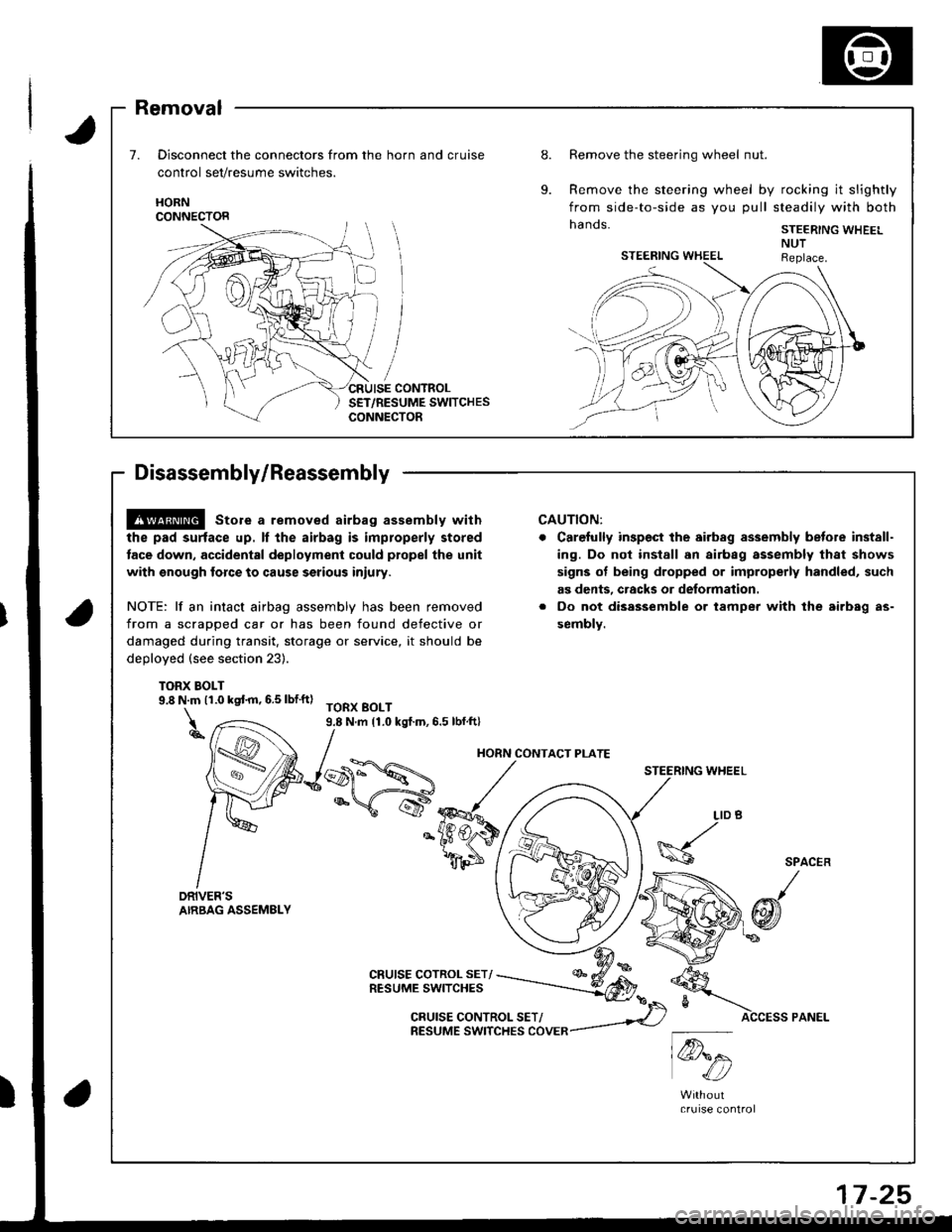
Removal
Disconnect the connectors from the horn and cruise
control set/resume switches.
Remove the steering wheel nut.
Remove the steering wheel by rocking it slightly
from side-to-side as you pull steadily with both
hands. STEER|NG WHEEL
HORNCONNECTOR
7 -25
@ store a removed airbag assembly with
the pad surtace up. ll the airbag is improperly stored
tace down. accidental deployment could propel the unit
with snough force to cause serious iniury.
NOTE: lf an intact airbag assembly has been removed
from a scrapped car or has been found defective or
damaged during transit, storage or service, it should be
deDloyed (see section 23).
TORX BOLT9.8 N.m (1.0 kqt m, 6.5 lbf'ft)TORX BOLT9.8 N.m 11.0 kgf.m,6.5 lbf.ft)
CRUISE COTROL SET/RESUME SWITCHES
CAUTION:
Carefully inspect the airbsg assembly betore inst8ll-
ing. Do nol install 8n airbag assembly that shows
signs ot being dropped or improperly handled, such
as dents, cracks or deformation.
Oo not disassemble or tampel with the airb8g as-
sembly.
STEERING WHEEL
\@.
LID
h6
w1c4:,/bA
4t
SPACER
@f
CRUISE CONTROL SET/RESUME SWITCHES COVER
HORN CONTACT PLATE
Page 676 of 1681
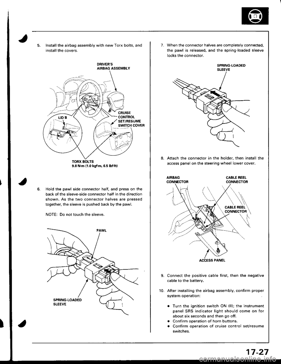
Installthe airbag assembly with new Torx bolts, and
installthe covers.
cRursECONTROLSET/RESUMEswtTcH covER
Hold the pawl side connector half. and press on the
back of the sleeve-side connector halt in the direction
shown. As the two connector halves are pressed
together, the sleeve is pushed back by the pawl.
NOTE: Do not touch the sleeve.
7.When the connector halves are completely connected.
the pawl is released. and the spring loaded sleeve
locks the connector.
SPRING.LOADEDSLEEVE
Attach the connector in the holder, then install the
access panel on the stee.ing wheel lower cover.
Connect the positive cable first. then the negative
cable to the battery.
After installing the airbag assembly, confirm proper
system operation:
. Turn the ignition switch ON (ll); the instrument
panel SRS indicator light should come on for
about six seconds and then go off.
. Confirm operation of horn buttons.
. Confirm operation of cruise control sevresume
switches.
10.
17-27
Page 707 of 1681
Power Steering Gearbox
Reassembly (cont'dl
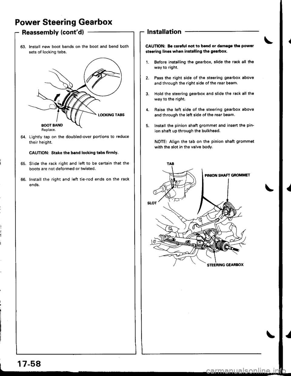
63. Install new boot bands on the boot and bend both
sets of locking tabs.
Lightly tap on the doubled-over portions to reduce
their height.
CAUTION: Stake ihe bsnd locking tabs tirmly.
Slide the rack right and ieft to be certain that the
boots are not deformed or twisted.
Install the right and left tie-rod ends on the rack
enos.
64.
lnstallation
CAUTION: Bo caretul not to bond or damrge the powcr
steering lines when in3t8lling the grlrbox.
1. Before installing the gearbox, slide the rack all the
way to right.
2, Pass the right side of the stsering gearbox above
and through the right side of the rear beam.
3. Hold the steering gearbox and slide the rack 8ll the
way to the right.
4. Rsise the left side of the steering gearbox above
and through the left side of the rear beam.
5. Install the pinion shaft grommet and insert the pin-
ion shaft up through the bulkhesd.
NOTE: Align the tab on the pinion shaft grommet
with the slot in the valve bodY.
oo.
tAa
17-58
Page 721 of 1681
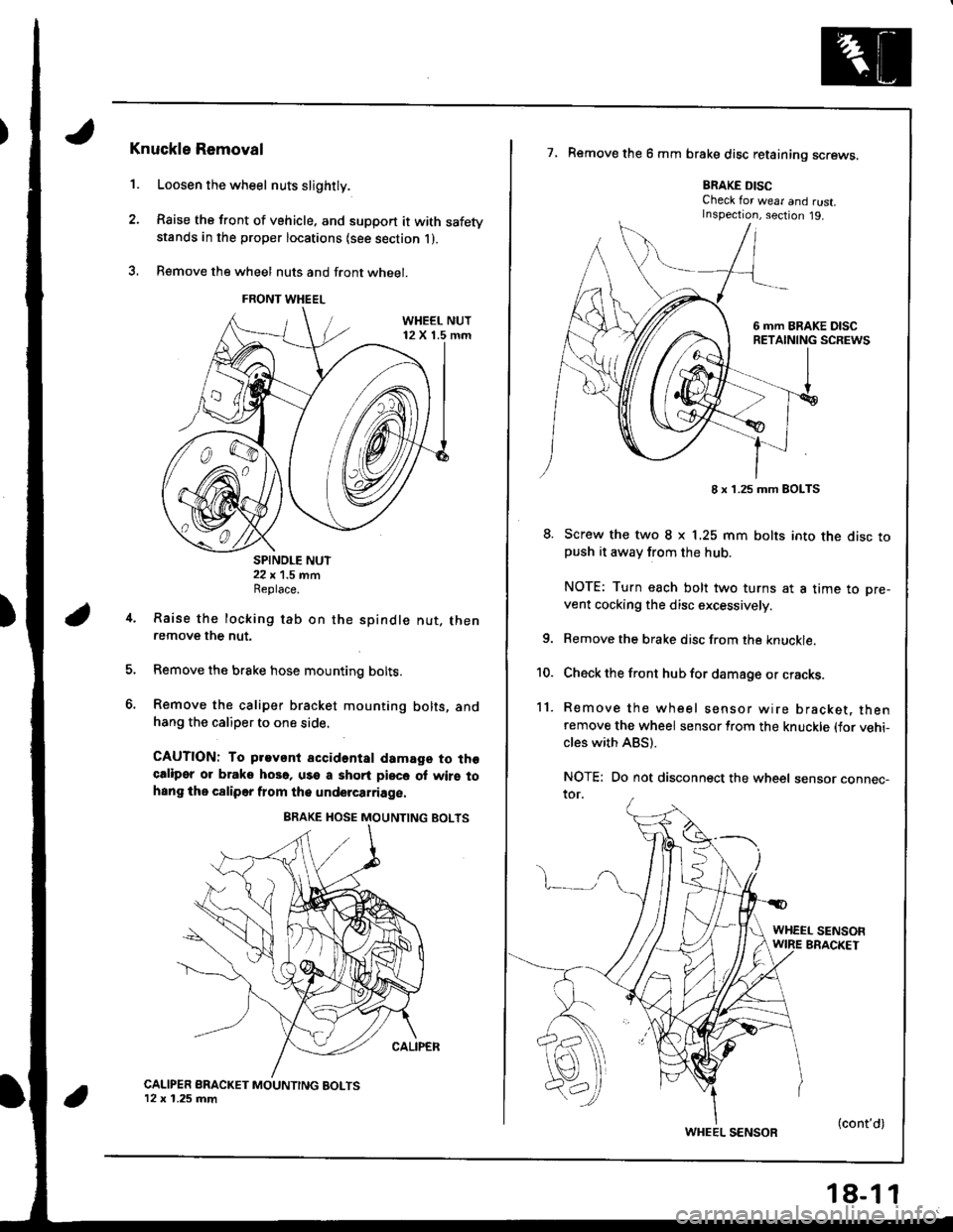
1.
Knuckle Removal
Loosen the wheel nuts slightly.
Raise the front of vehicle. and support it with safetystands in the proper locations {see section l ).
B€move the wheel nuts and front wheel.
SPINDLE NUT22 x 1.5 mmReplace.
Raise the locking tab on the
remove the nut.
spindle nut. then
Remove the brake hose mounting bolts.
Remove the caliper bracket mounting bolts, andhang the caliper to one side.
CAUTION: To pravant accidental damage to thgcaliper or braks hoso, use a shqrt piece of wirs tohsng the c8liper flom the undercarriage.
CALIPER BRACKET MOUNTING BOLTS12 x 1.25 mm
7, Remove the 6 mm brake disc retaining screws.
BRAKE DISCCheck for wear and rust.Inspection, section j9.
8. Screw the two I x L25 mm bolts into the disc topush it awav from the hub.
NOTE: Turn each bolt two turns at a time to pre-
vent cocking the disc excessively.
Remove the brake disc from the knuckle.
Check the front hub for damage or cracks.
Remove the wheel sensor wire bracket, thenremove the wheel sensor lrom the knuckle (for vehi-cles with ABS).
NOTE: Do not disconnect the wheel sensor connec-ror.
4.
6.
10.
11.
WHEEL SENSOFWIRE BRACKET
FRONT WHEEL
8 x 1.25 mm BOLTS
WHEEL SENSOR(cont'd)
Page 739 of 1681
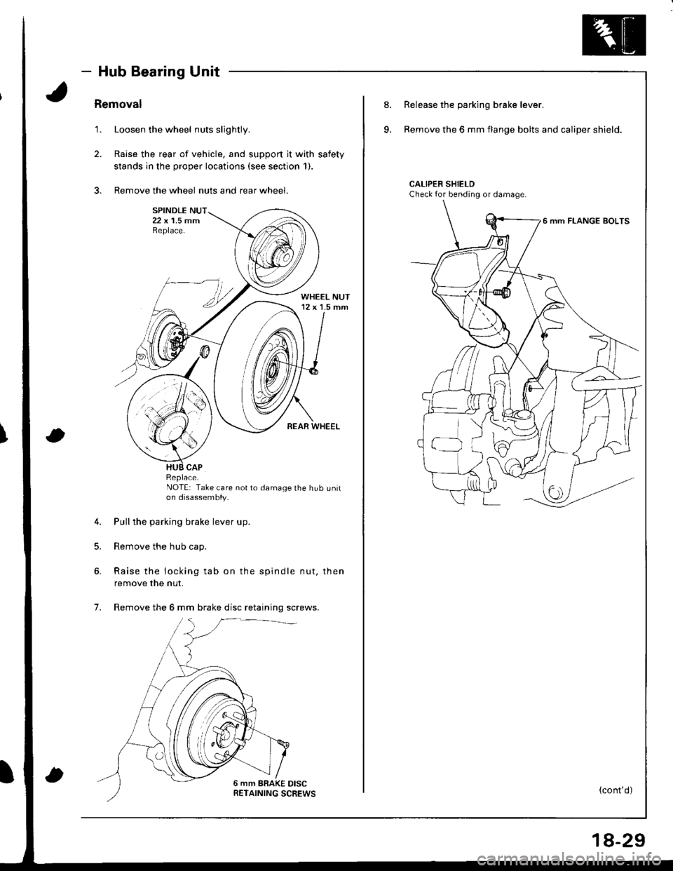
- Hub Bearing Unit
Removal
1. Loosen the wheel nuts slightly.
2. Raise the rear of vehicle, and support it with safety
stands in the proper locations (see section 1).
3. Remove the wheel nuts and rear wheel.
NOTE: Take care not to damage the hub uniton disassembly.
4. Pull the parking brake lever up.
5. Remove the hub cap.
6. Raise the locking tab on the spindle nut, then
remove the nut.
7. Remove the 6 mm brake disc retaining screws.
Replace.
8.
9.
Release the parking brake lever.
Remove the 6 mm flange bolts and caliper shield.
CALIPER SHIELDCheck for bending or damage.
6 mm FLANGE BOLTS
(cont'd)
18-29
Page 757 of 1681
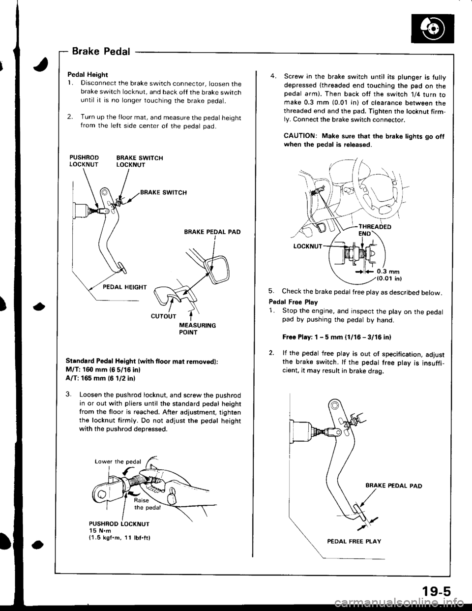
a
BrakePedal
Pedal Height
1. Disconnect the brake switch connector, loosen thebrake switch locknut, and back oll the brake switchuntil it is no longer touching the brake pedal.
2. Turn up the jloor mat, and measure the pedal heightfrom the lett srde center of the pedal pad.
PUSHROD ERAKE SWITCHLOCKNUT LOCKNUT
swtTcH
BRAKE PEOAL PAOI
MEASURINGPOINT
Standard Pedal Hsight (wiih ftoor m8t removedl:
M/T: 160 mm {6 5/16 in}
A/T: 165 mm (6 1/2 in)
3. Loosen the pushrod locknut, and screw the pushrod
in or out with pliers until the standard pedal height
from the floor is reached. After adjustment, tighten
the locknut firmly. Do not adjust the pedal height
with the pushrod depressed.
{1.5 kgf.m, 11 lbt.ftl
19-5
Screw in the brake switch until its plunger is fully
depressed (threaded end touching the pad on thepedal arm). Then back off the switch 1/4 turn tomake 0.3 mm (0.01 in) of clearance between thethreaded end and the pad. Tighten the locknut firm-ly. Connect the brake switch connector.
CAUTION: Make sure that the brake lights go oflwhen the pedal is released.
5. Check the brake pedal free play as described below.
Pedal Free Play
1. Stop the engine, and inspect the play on the pedal
pad by pushing the pedal by hand.
Free Play: 1 - 5 mm {l/16 - 3/16 in)
2. lf the pedal free play is out of specification, adjustthe brake switch. tf the pedal free play is insuffi_cient, it may result in brake drag.
PEDAL PAD
Page 758 of 1681
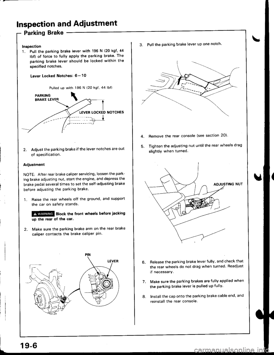
Inspection and Adiustment
Parking Brake
Inspection
1. Pull the parking btake lever with 196 N
lbf) of force to Jully apply the parking
parking brake lever should be locked
soecified notches.
Lever Locked Notches: 6- l0
{20 kgf, 44
brake. The
within the
Pulled up with 196 N {2O kgf, 44 lbf)
LEVER LOCKED NOTCHES
2, Adjust the parking brake if the lever notches are out
of specification.
Adjustment
NOTE: After rear brake caliper servicing.loosen the park-
ing brake adjusting nut, start the engine, and depress the
brake pedal several times to set the self-adjusting brake
before adiusting the parking brake
1. Raise the rear wheels oIt the ground. and suppon
the car on safety stands.
!!@ ato"t the trort whoels bsfore jacking
up the roal ot tha car'
2. Make sure the parking brake arm on the rear brake
caliDer contacts the brake caliper pin.
19-6
8.
3. Pullthe parking brake lever up one notch'
Remove the rear console {see section 20)'
Tighten the adjusting nut until the rear wheels drag
slightly when turned.
7.
Release the parking brake lever fully, and check that
the rear wheels do not drag when turned. Readjust
if necessary.
Make sure the parking brakes are fully spplied when
the parking brake lever is pulled up fully.
Install the cap onto the parking brake cable end, and
reinstall the rear console.
Page 760 of 1681
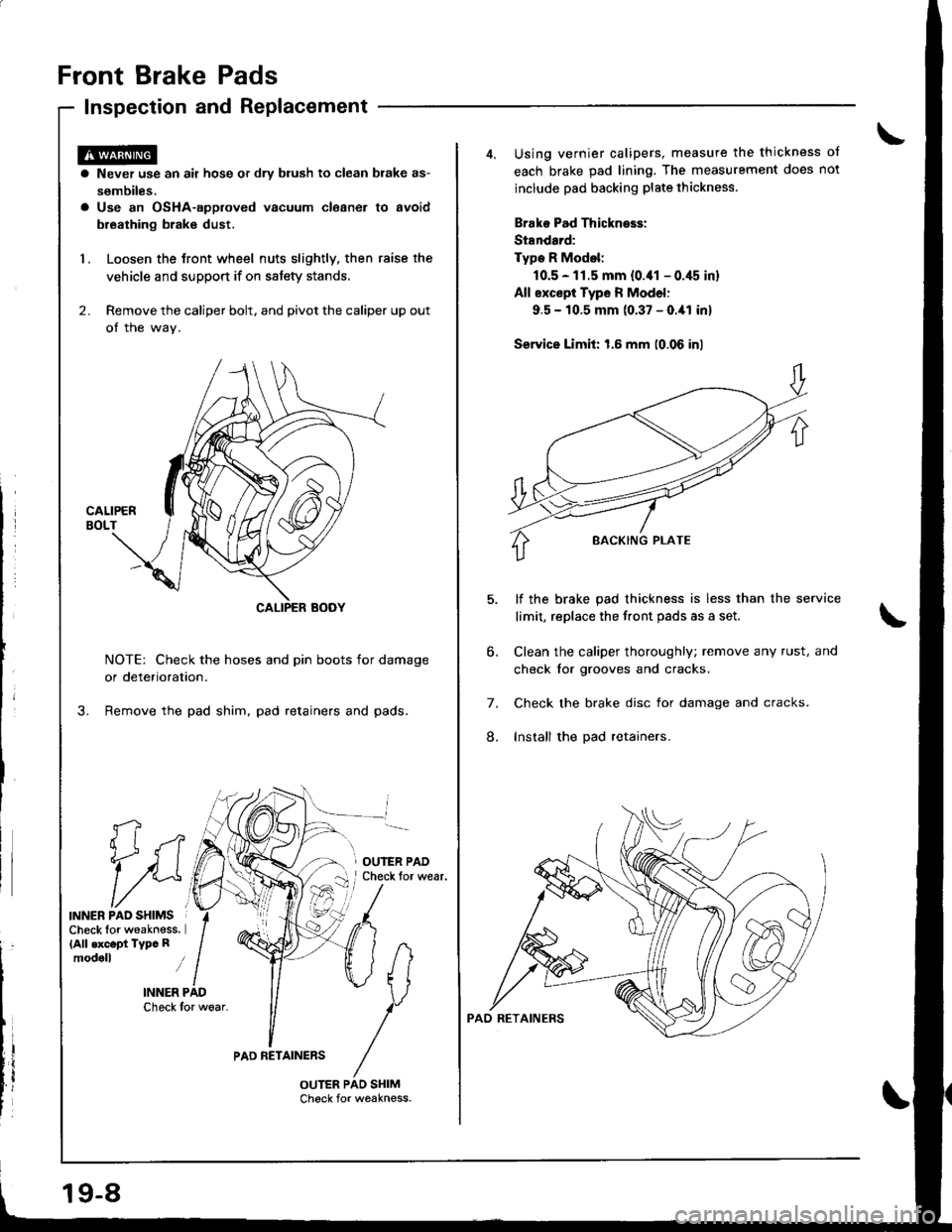
Front Brake Pads
Inspection and Replacement
fi
1i
INNER PAO SHIMSCheck lor weakness.(All .xc.pt Typc Rmodoll i
INNER PADCheck for woar.
a Never use an air hose or dry blush to clean brake as-
sembiles.a Use an OsHA-approved vacuum cleaner to avoid
breathing brak€ dust.
1. Loosen the Jront wheel nuts slightly, then raise the
vehicle and support if on satety stands,
2. Remove the caliper bolt, and pivot the caliper up out
of the wav.
NOTE: Check the hoses and pin boots for damage
or deterioration.
Remove the pad shim, pad retainers and pads.
OUIER PADCheck tor wear.
PAD RETAINERS
19-8
Using vernier calipers, measure the thickness ot
each brake pad lining. The measurement does not
include pad backing plate thickness.
Brako Pad Thickness:
St8ndard:
Type R Modol:
10.5 - 11.5 mm {0.41 - 0.45 in}
All except Type R Model:
9.5 - 10.5 mm (0.37 - O.ial inl
Service Limit: 1.6 mm (0.06 inl
lf the brake pad thickness is less than the service
limit, replace the front pads as a set,
Clean the caliper thoroughly; remove any rust, and
check tor grooves and cracks.
Check the brake disc for damage and cracks.
Install the pad retainers.
6.
7.
8.
Page 762 of 1681
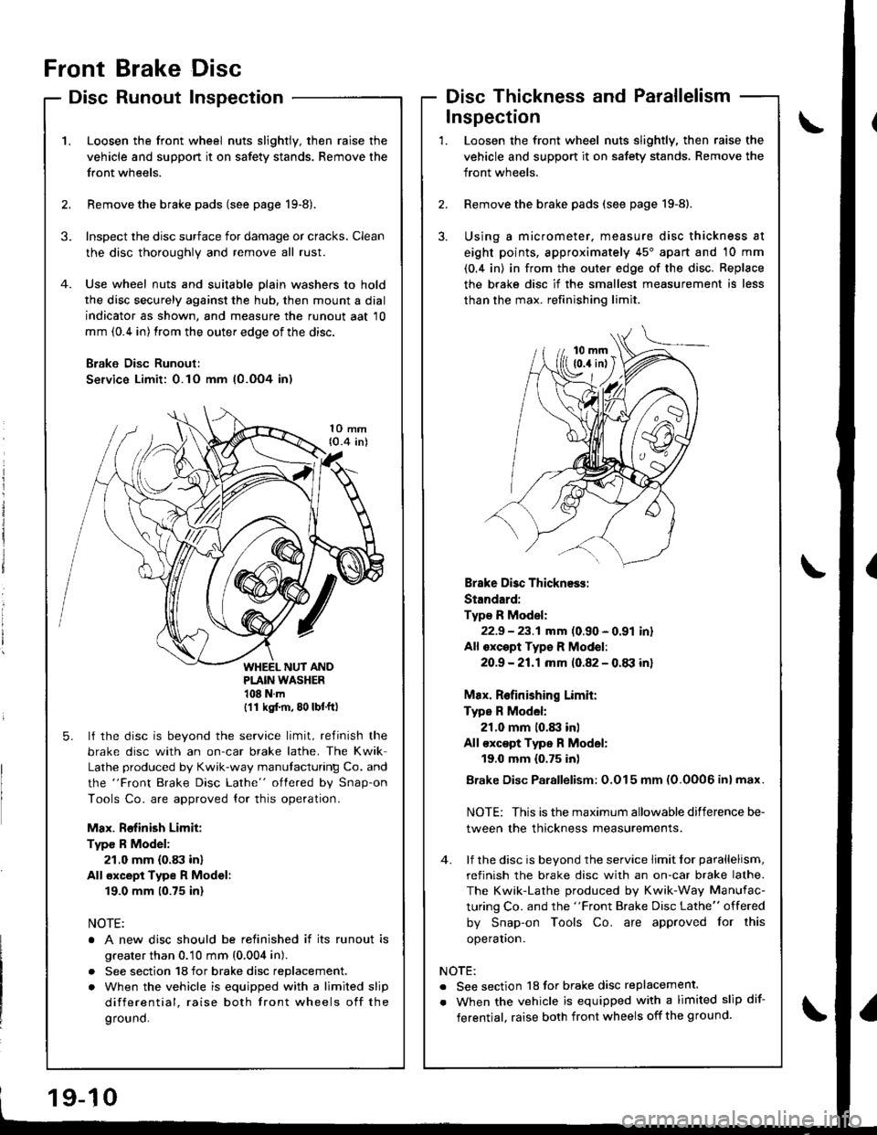
Front
Disc
Brake
Runout
Disc
InspectionDisc Thickness and Parallelism
\'L
2.
Loosen the front wheel nuts slightly, then raise the
vehicle and suppon it on safety stands. Remove the
front wheels.
Remove the brake pads (see page 19-8).
Inspect the disc surface for damage or cracks. Clean
the disc thoroughly and remove all rust.
Use wheel nuts and suitable plain washers to hold
the disc securely against the hub, then mount a dial
indicator as shown, and measure the runout aat 10
mm (0.4 in) from the outer edge of the disc.
B;ake Disc Runoul:
Service Limit: 0.10 mm (0.OO4 in)
3.
1O mm{0.4 inl
PLAIN WASHER108Nm(11 ksl.m, 80 lbf.ft)
5. lf the disc is beyond the service limit, refinish the
brake disc with an on-car brake lathe. The Kwik
Lathe produced by Kwik-way manutacturing Co. and
the "Front Brake Disc Lathe" oflered by Snap-on
Tools Co. are approved {or this operation.
Max. Rofinish Limit:
Type R Model:
21.0 mm (0.83 in)
All €xcept Type R Model:
19.0 mm (0.75 inl
NOTE:
o A new disc should be relinished if its runout is
greater than 0.10 mm (0,004 in).
. See section 18 for brake disc replacement.
. When the vehicle is equipped with a limited slip
differential, raise both front wheels off the
ground.
3.
Loosen the front wheel nuts slightly, then raise the
vehicle and support it on safety stands, Remove the
front wheels.
Remove the brake pads (see page 19-8).
Using a micrometer, measure disc thickness at
eight points, approximately 45'apart and 10 mm
(0.4 in) in from the outer edge of the disc. Replace
the brake disc if the smallest measurement is less
than the max. refinishing limit.
Inspection
2.
1.
Brake Disc Thickness:
Standard:
Type R Model:
22.9 - 23.1 mm (0.90 - 0.91 inr
All oxcept Typ€ R Mod€l:
2O.9 -21.1mm 10.82 - 0.tB inl
Max. Relinishing Limit:
Type R Model:
21.0 mm 10.83 inl
All €xc€pt Type R Model:
19.0 mm {0.75 inl
Brake Disc Parallelism: O.O15 mm (0.0006 inl max.
NOTE: This is the maximum allowable difference be-
tween the thickness measurements.
4. lf the disc is beyond the service limit lor parallelism,
refinish the brake disc with an on-car brake lathe.
The Kwik-Lathe produced by Kwik-Way Manufac-
turing Co. and the "Front Brake Disc Lathe" offered
by Snap-on Tools Co. are approved for this
operaton.
NOTE:
. See section 18 for brake disc replacement.
. When the vehicle is equipped with a limited slip dif-
ferentjal, raise both front wheels off the ground.