battery HONDA INTEGRA 1998 4.G Manual PDF
[x] Cancel search | Manufacturer: HONDA, Model Year: 1998, Model line: INTEGRA, Model: HONDA INTEGRA 1998 4.GPages: 1681, PDF Size: 54.22 MB
Page 1070 of 1681
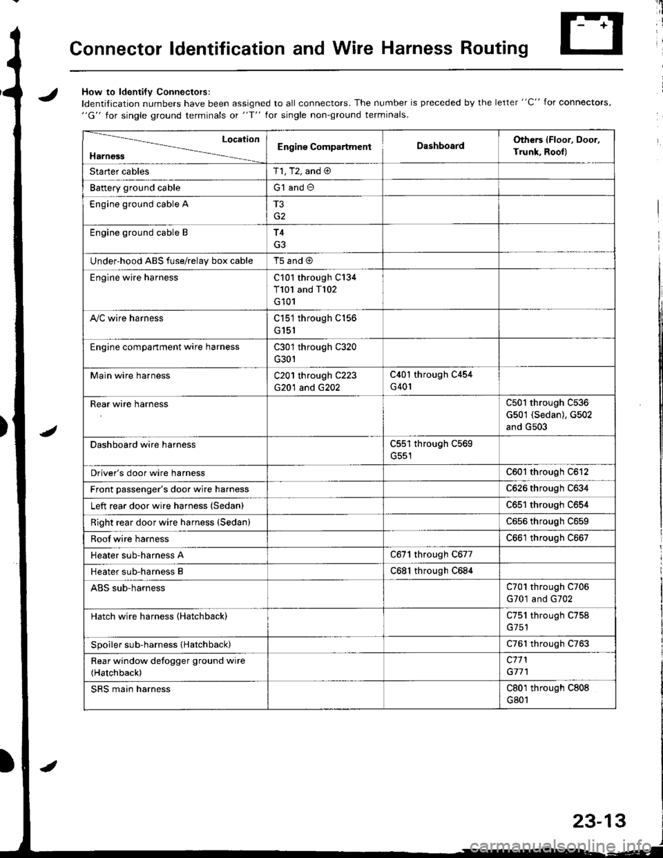
Connector ldentification and Wire Harness Routing
JHow to ldenti{v Connectors:
ldentification numbers have been assigned to all connectors. The number is preceded by the letter "C" for connectors,"G" for single ground terminals ot "f" lor single non-ground terminals.
/
Location
HarnossEngine CompartmentDashboardOthers (Floor, Door,
Trunk. Rooll
Starter cablesT1, T2, and @
Battery ground cableG1 and O
Engine ground cable A
G2
Engine ground cable BT4
G3
Under-hood ABS fuse/relav box cableT5 and @
Engine wire harnessC101 through C134
T101 and T102
G101
A,/C wire harnessC151 through C156
G151
Engine compartment wire harnessC301 through C320
G301
Main wire harnessC201 through C223
G20'l and G202
C40l through C454
G401
Rear wire harnessC501 through C536
G501 (Sedan), G502
and G503
Dashboard wire harnessC551 through C569
G551
Driver's door wire harnessC601 through C612
Front passenger's door wire harnessC626 through C634
Left rear door wire harness (Sedan)C65l through C654
Right rear door wire harness (SedanlC656 throughc659
Roof wire harnessC661 through C667
Heater sub-harness AC671 through C677
Heater sub-harness BC68l through C684
ABS sub-harnessC701 through C706
G701 and G702
Hatch wire harness (Hatchback)C751 through C758
Spoiler sub-harness {Hatchback)C761 through C763
Rear window defogger ground wire
(Hatchback)
c11 l
G77'l
SRS main harnessC801 through C808
G801
23-13
Page 1071 of 1681
Connector ldentification and Wire Harness Routing
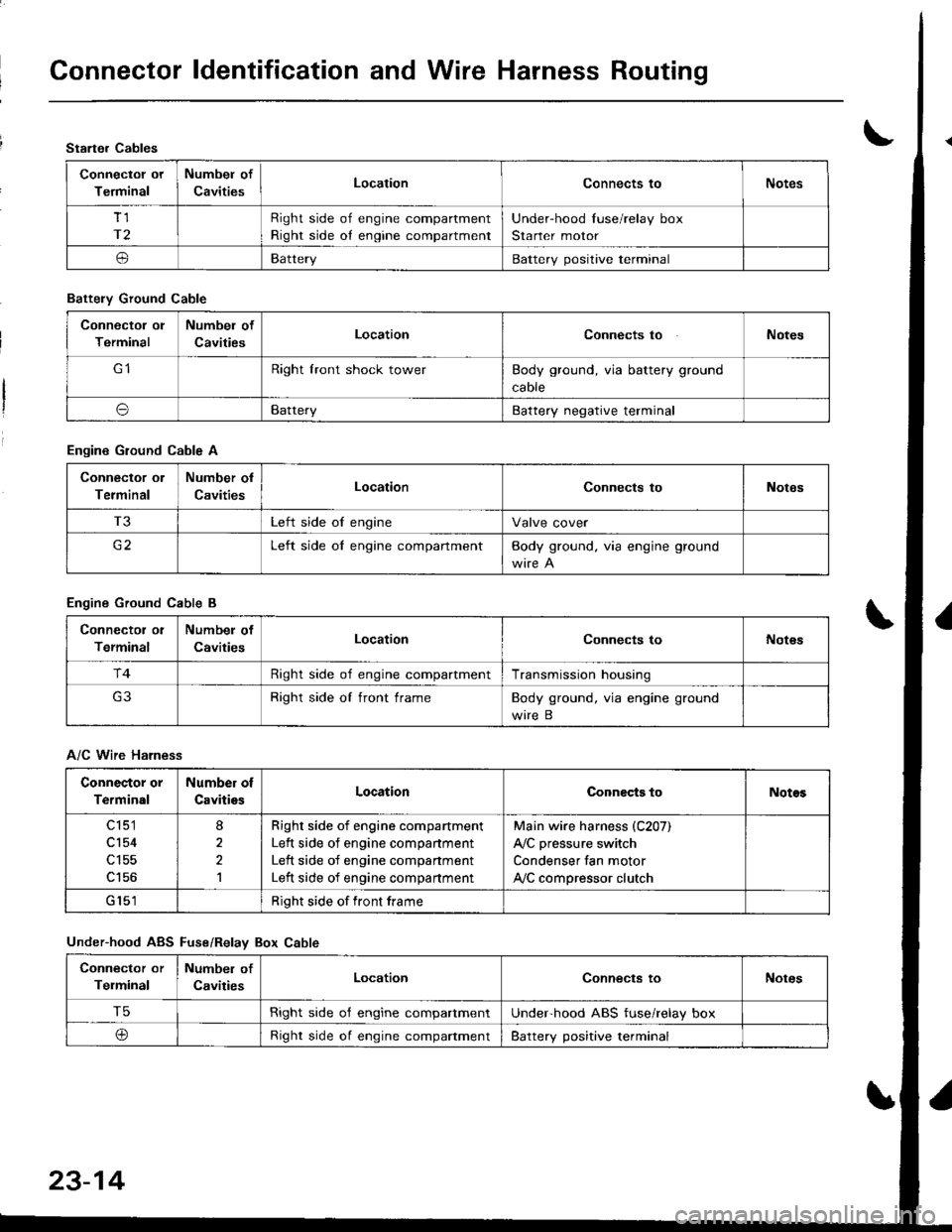
Starter Cables
Connectol ot
Terminal
Numbel of
CavitiesLocationConnects toNotes
Tl
r2
Right side of engine compartment
Right side oI engine compartment
Under-hood Iuse/relay box
Starter motor
oBatteryBattery positive terminal
Battely Ground Cable
Connector ol
Terminal
Numbel of
CavitiesLocationConnects toNotes
Right lront shock towerBody ground, via battery ground
caore
oBatteryBattery negative terminal
Engine Ground Cable A
Connector ol
Terminal
Number ol
CavitiesLocationConnects toNotes
T3Left side of engineValve cover
c2Left side oI engine compartmentBody ground. via engine ground
Engine Ground Cable B
Connector ol
Terminal
Numbel of
CavitiesLocationConnects toNot€s
r4Right side of engine compartmentTransmission housing
Right side of front frameBody ground, via engine ground
wire B
A/C Wire Harness
Connector or
Terminal
Number of
CavitiesLocationConnects toNotos
c 151
cl54
c156
8
2,l
Righr side of engine compartment
Left side of engine companment
Left side of engine compartment
Left side of engine compartment
Main wire harness (C207)
A,/C pressure switch
Condenser fan motor
ly'C compressor clutch
Right side of front frame
Under-hood ABS Fuse/Relav Box Cable
Connector or
Telminal
Number of
CavitiesLocationConnects toNotes
T5Right side o'f engine compartmentUnderhood ABS fuse/relay box
@Right side oI engine compaftmentBattery positive terminal
23-14
Page 1109 of 1681
![HONDA INTEGRA 1998 4.G Manual PDF Fuses
Under-hood Fuse/Relay Box
AITEFNATOR[To .ngine wiro hrrn83 1T101)l
BATTERYlTo stano. csblca lTlll
C!104 [To condenso] fan relayl
*: Not u6edclutch l.hyl
NOTE: View from the backside of the under HONDA INTEGRA 1998 4.G Manual PDF Fuses
Under-hood Fuse/Relay Box
AITEFNATOR[To .ngine wiro hrrn83 1T101)l
BATTERYlTo stano. csblca lTlll
C!104 [To condenso] fan relayl
*: Not u6edclutch l.hyl
NOTE: View from the backside of the under](/img/13/6069/w960_6069-1108.png)
Fuses
Under-hood Fuse/Relay Box
AITEFNATOR[To .ngine wiro hrrn83 1T101)l
BATTERYlTo stano. csblca lTlll
C!104 [To condenso] fan relayl
*: Not u6edclutch l.hyl
NOTE: View from the backside of the under-hood fuse/relav box.
ClOg [To main wiro ha]ne3s {C215ll
C!107 [To blow.r motor r.l.yl
C908 [To m.in wiro h.rn.$ (C2l7ll
rr17
LI
Fl51
LI
rl56
lJ
rr51
IJ
C905 [To A/C compr.ssor C9O6 [To radirto] fan
23-52
Cltl1 lTo main wire harness lc218ll: USA
C€10 [To mrin wir. hlrnoit lC216ll
Page 1110 of 1681
J
)1 -
Fuso NumborAmpsWir€ ColorComponent(s) or Circuh(rl Protastcd
41100 ABattery. power distribution
4240AWHT/BLKlgnition switch (BAT)
437.5 AWHT/REDCeiling light, cargo area light, data link connector (DLCl, power
antenna connector
44't5 AYEL/WHTPGM-Fl main relay
45Not used
4640AWHT/8LU
No. 7 (20 A) fuse (Via power window relay), No. 8 (20 A) tuse (Via
power window relay)
No. 10 (20 A) fuse (Via power window relay), No. 11 (20 A) fuse (Via
power window relay)
417.5 AWHT/BLUClock,8udio unit connector, ECM, TCM, Maint€nance reminder unit
4840AWHTCombination light switch (Headlight)
4930AWHT/BLUMoonroof relay
5040AWHT/GRNRear window defogger {Via rear window defogger relay)
51154WHTCombination light switch (Dash lights)
20AWHT/GRNHorn, horn relay, brake lights, AgS control unit, ECM, TCM
10AWHT/GRNTurn signal/hazard relay, hazard warning light
5440AWHT/flEDNo. 1 (20 A) fuse
40ABLU/WHTBlower motor (Via blower motor relsy)
56204BLU/BLKCondenser fan motor (Via condenser {an motor relay)
REDA,/C compressor clutch (via Ay'c comp.essor clutch relay)
57204BLVREDRadiator f8n motor (Via radiator fan relay)
23-53
Page 1124 of 1681
Battery
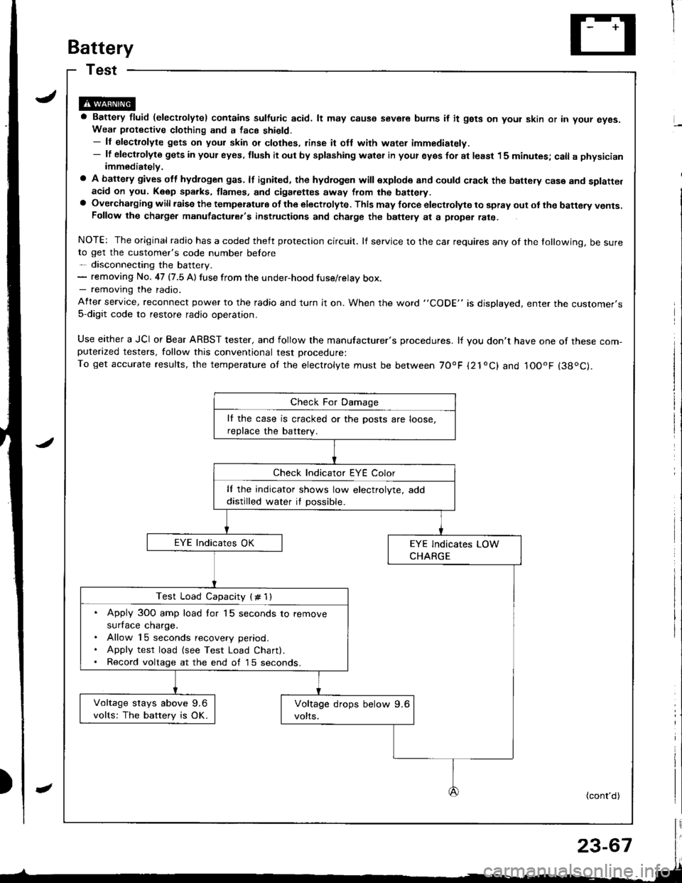
a Battery fluid (electrolytel contains sulfuric acid. lt may causo severe burns if it gsts on yout skin or in your eyes.Wear piotective clothing and a face shield.- ll electrolyte gets on your skin or clothes, rinse it ofl with water immediately.- lf electlolyte gets in your eyes, tlush it out by splashing water in your eyes for at least 15 minutes; call a physicianimmediately.
a A battery gives off hydlogen gas. lf ignited, the hydrogen will explode and could crack the battery case and splatte.acid on you. K6ep sparks, flames, and cigarettes away from the battery.a Overchalging will raisc the temperatulg of the electrolyte. This may force electrolyte to spray out ol the battery vents.Follow the chatge. manutacturer's instructions and charge the baftely at a ptope. rate.
NOTE: The original radio has a coded theft protection circuit. lf service to the car requires any of the tollowing, be sureto get the customer's code number before- disconnecting the battery.- removing No. 47 (7.5 A) fuse from the under-hood fuse/relay box.- removing the radio.
After service, reconnect power to the radio and turn it on. When the word "CODE" is displayed, enter tne customer's5-digit code to restore radio operation,
Use either a JCI or Bear ARBST tester, and follow the manufacturer's procedures. lf you don't have one of these com-puterazed testers, follow this conventional test Drocedure:To get accurate results, the temperature of the electrolyte must be between 70'F {21oC} and IOOoF (38oC).
lf the case is cracked or the posts are loose,
reDlace the batterv.
lf the indicator shows low electrolyte, add
distilled water if possible.
Test Load Capacity (# 1l
. Apply 3O0 amp load for 15 seconds to remove
surface charge.. Allow 15 seconds recovery period.. Apply test load {see Test Load Chart).. Record voltage at the end of l5 seconds.
Voltage stays above 9.6
volts: The battery is OK.
(cont'd)
Page 1125 of 1681
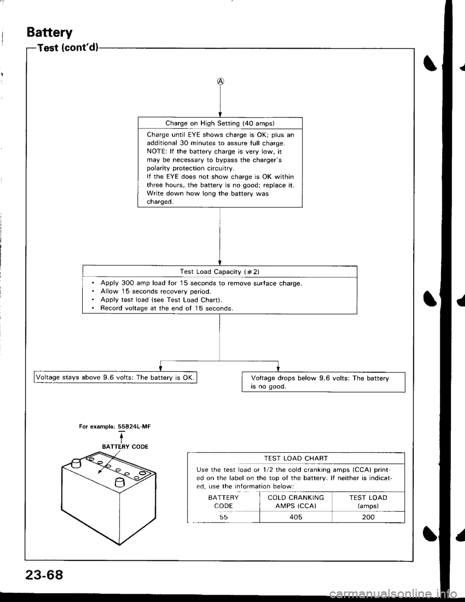
Battery
Test (cont'dl
Charge on High Setting (4O amps)
Charge until EYE shows charge is OK; plus an
additional 30 minutes to assure tull charge.
NOTE: lf the battery charge is very low, it
may be necessary to bypass the charger's
polarity protection circuitry.
lf the EYE does not show charge is OK within
three hours, the battery is no good; replace it.
Write down how long the battery was
charged.
Test Load Capacity (# 2)
Apply 3O0 amp load for '15 seconds to remove surtace charge.
Allow '15 seconds recoverv oeriod.
Apply test load (see Test Load Chart).
Record voltage at the end ol 15 seconds.
Voltage stays above 9.6 volts: The battery is OK. IVoltage drops below 9.6 volts: The battery
rs no good.
For example:
BATT
55B24L.MF
TIERY CODE
TEST LOAD CHART
Use the test load ot 112 the cold cranking amps (CCA) print-
ed on the label on the top oI the battery. lf neither is indicat-
ed, use the information below:
23-68
Page 1129 of 1681
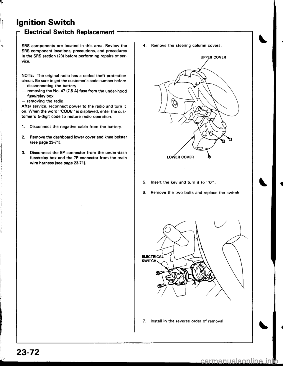
lgnition Switch
Electrical Switch Replacement
SRS comoonents are located in this ar8a. Review thE
SRS component locations, precautions, and procedures
in the SRS section (23) before performing repairs or ser-
vice.
NOTE: The original radio has a coded thett protection
circuit, Be sure to get the customer's code number before- disconnecting the battery.- removing th6 No. 47 (7.5 A) tuse from the under-hood
tuse/relav box,- removing the radio.
After service, reconnect oower to the radio and turn it
on. When the word "CODE" is displayed, enter the cus-
tomer's s-digit code to restore radio operation.
1. Disconnect the negative cable from the battery.
4. Remove the steering column covers.
Romovs ths dashboard lower cover 8nd knes bolster(se6 p8g6 23-71).
Disconnsct th6 5P connector from th6 under-dash
fuse/rel8y box 6nd th€ 7P conn€ctor from the main
wire harne$ (s6e page 23-711.
5.Insert the key and turn it to "O".
Remove the two bolts and replace the switch6.
UPPER COVER
7. Install in the reverse order of removal.
23-72
Page 1130 of 1681
;
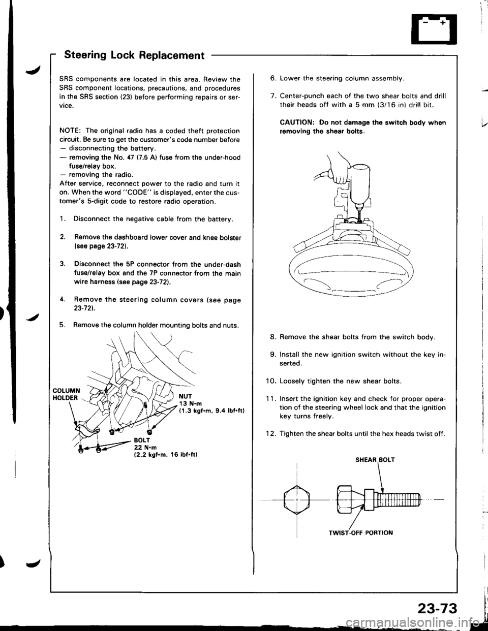
Steering Lock Replacement
SRS components are located in this area. Review the
SRS component locations, precautions, and procedures
in the SRS section (23) before performing repairs or ser-
vice.
NOTE: The original radio has a coded theft protection
circuit. Be sure to get the customer's code number before- disconnecting the battery.- removing the No. 47 (7.5 A) fuse trom the under-hood
fuse/relav box.- removing the radio.
After service, reconnect power to the radio and turn it
on. When the word "CODE" is displayed. enter the cus-
tomer's 5-digit code to restore radio operation.
1. Disconnect the negative cable from the battery.
2. Remove ths dsshboard lower cover and knee bolster(s6o p8ge 23-72).
3, Disconnect the 5P connector from the under-dash
fuse/relay box and the 7P connsctor from th€ main
wire harness (see page 23-72l.,
4. Remove the steering column covars (see page
23-721.
5. Remove the column holder mounting bolts and nuts.
NUT13 N.m(1.3 kgl.m, 9.4 lbt.ftl
BOLT22 N.m(2.2 kgf.m, 16 lbf.ftl
6.
7.
Lower the stee.ing column assembly.
Center-ounch each of the two shear bolts and drill
their heads oft with a 5 mm {3/16 in) drill bit.
CAUTION: Do not damage the switch body when
lemoving th€ sheal bolts.
Remove the shear bolts from the switch body.
Install the new ignition switch without the key in-
serted.
1O. Loosely tighten the new shear bolts.
11. Ins€rt the ignition key and check for proper opera-
tion of the sleering wheel lock and that the ignition
key turns freely.
12. Tighten the shear bolts until the hex heads twist off.
8.
Page 1131 of 1681
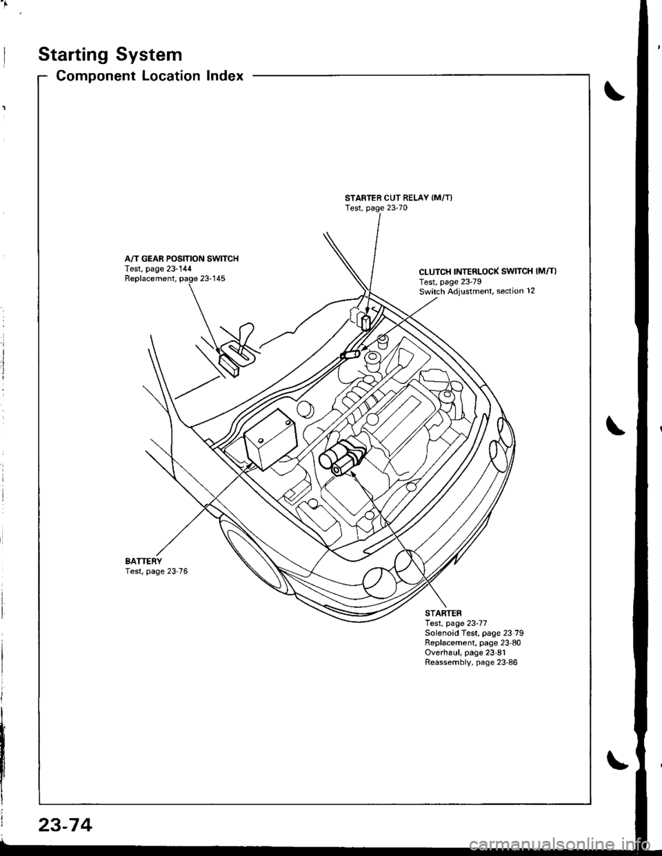
Starting System
Component LocationIndex
STARTER CUT RELAY (M/T)
Test, page 23-70
A/T GEAR POSITION SWITCHTest, page 23-144CLUTCH INTERLOCK SWITCH IM/T}Test, page 23-79Switch ,Adiustment, section 12
Replacement,
BATTERYTest, page 23 76
STARTERlest, page 23-77Solenoid Test, page 23 79Replacement, page 23'80Overha!1, page 23'81Reassembly, page 23'86
23-74
Page 1134 of 1681
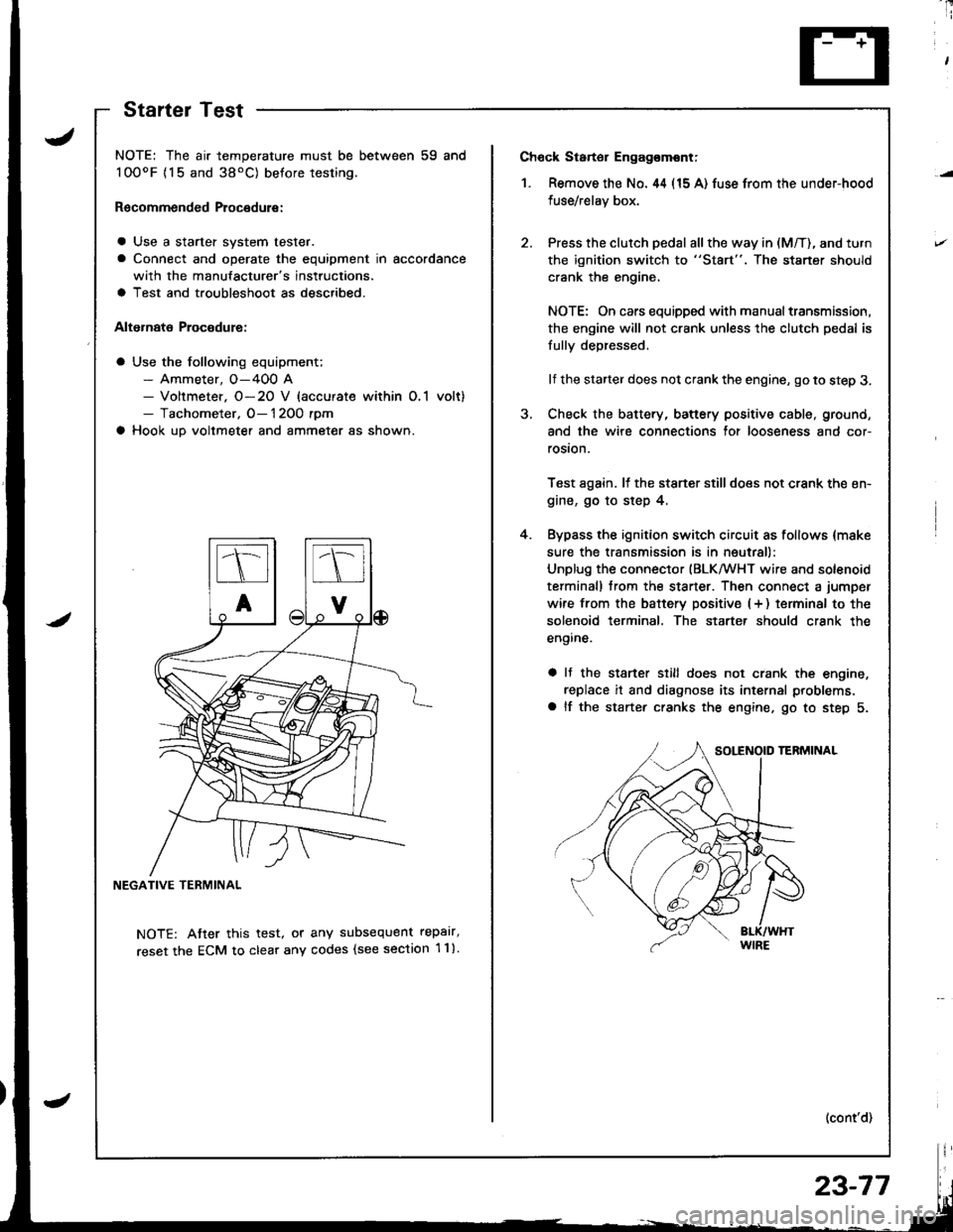
Ch6ck Starter Engag€mont;
1. Remove the No. 44 (15 A) fuse from the under-hood
fuse/relay box,
Press the clutch pedal all the way in (M/T), and turn
the ignition switch to "St8rt". The staner should
crank the engine,
NOTE: On cars equipped with manual transmission,
the engine will not crank unless the clutch pedal is
fully depressed.
lf the starter does not crank the engine, go to step 3.
Check the battery, battery positive cable, ground,
and the wire connections for looseness and cor-
rosion.
Test again. lf the stsner stilldoes not crank the en-
gine, go to step 4.
Bypass the ignition switch circuit as follows {make
sure the transmission is in neutral)
Unplug the connector (BLKMHT wire and solenoid
terminal) trom the staner. Then connect a jumper
wire from the batterv positive (+ ) terminal to the
solenoid terminal. The starter should crank the
engine.
a It the stsrter still does not crank the engine,
replace it and diagnose its internal problems,
a lf the starter cranks the engine. go to step 5.
(cont'd)
4.
NOTE: The air temperature must be between 59 and
100oF {15 and 38'C) betore testing.
Recommended Procedure:
a Use a starter system tester.
a Connect and operate the equipment in accordance
with the manufacturer's instructions.
a Test and troubleshoot as described.
Alternate Procodure:
a Use the following equipment;- Ammeter, O-400 A- Voltmeter. O-20 V (accurate within O,1 volt)- Tachometer, O- 1 2OO rpm
a Hook up voltmeter and ammeter as shown.
NEGATIVE TERMINAL
NOTE: Atter this test, or any subsequent repalr,
reset the ECM to clear any codes (see section 1 1).
StartelTest
23-77