battery HONDA INTEGRA 1998 4.G Workshop Manual
[x] Cancel search | Manufacturer: HONDA, Model Year: 1998, Model line: INTEGRA, Model: HONDA INTEGRA 1998 4.GPages: 1681, PDF Size: 54.22 MB
Page 1290 of 1681
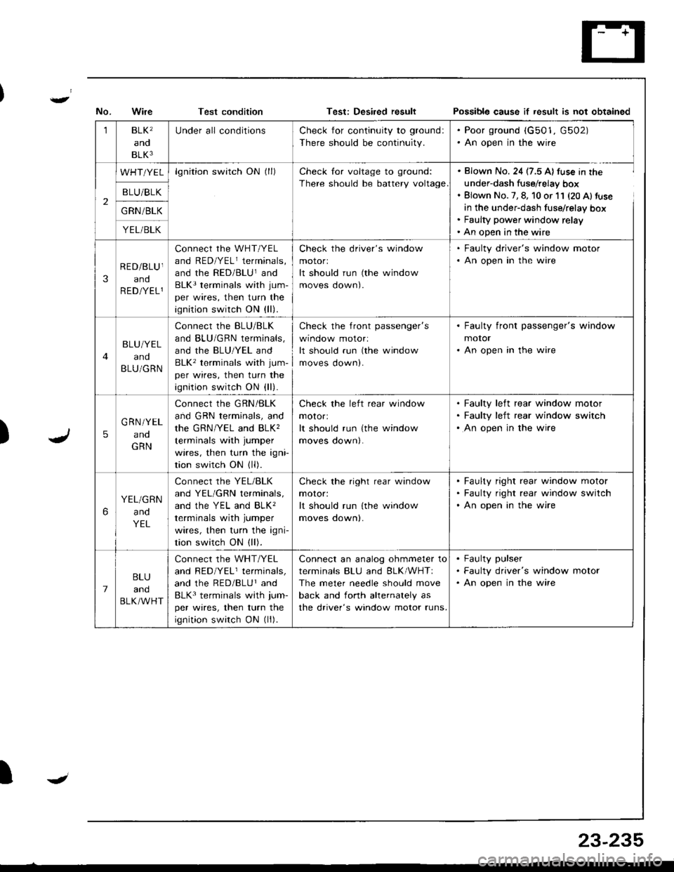
Test conditionPo$sible cause if result is not obtained
)
1BLK'
and
BLK3
Under all conditionsCheck for continuity to ground:
There should be continuity.
. Poor ground (G501, G502). An open in the wire
2
WHT/YELlgnition switch ON (ll)Check for voltage to ground:
There should be battery voltage
. Blown No. 24 (7.5 A) fuse in the
under-dash fuse/relay box. Blown No. 7, 8, 10 or 11 (20 Al fuse
in the under-dash fuse/relay box. Faulty power window relay' An open in the wire
B LU/BLK
G RN /BLK
YEL/BLK
3
RED/BLU I
and
R ED/YEL1
connect rhe wHT/YEL
and RED/YELr terminals,
and the RED/BLUland
BLK3 terminals with jum-
per wires, then turn the
ignition switch ON (ll).
Check the driver's window
motorl
It should run (the window
moves oown).
. Faulty driver's window motor. An open in the wire
BLU/YEL
and
BLU/GRN
Connect the BLU/BLK
and BLU/GRN terminals,
and the BLU/YEL and
BLK' terminals with jum-
per wires, then turn the
ignition switch ON (ll).
check the front passenger's
wtnoow molor:
It should run (the window
moves down).
. Faulty front passenger's window
motor. An open in the wire
5
G RN/YEL
ano
GRN
Connect the GRN/BLK
and GRN terminals, and
the GRN/YEL and BLK,
terminals with jumper
wires, then turn the igni
tion switch ON (ll).
Check the left rear window
motor:
It should run {the window
moves down|.
Faulty left rear window motor
Faulty left rear window switch
An open in the wire
6
YEL/GRN
and
YEL
Connect the YEL/BLK
and YEL/GRN terminals,
ANd thc YEL ANd BLK'
terminals with jumper
wires, then turn the igni-
tion switch ON (ll).
Check the right rear window
moror:
It should run lthe window
moves oownl.
Faulty right rear window motor
Faulty right rear window switch
An open in the wire
7
BLU
and
BLK/WHT
Connect the WHT/YEL
and RED/YELr terminals,
and the RED/BLUr and
BLK3 terminals with jum-
per wires, then turn the
ignition switch ON (ll).
Connect an analog ohmmeter to
terminals BLU and BLK/WHTI
The meter needle should move
back and fonh ahernalely as
the driver's window motor runs.
Faulty pulser
Faulty driver's window motor
An open in the wire
IJ
23-235
Page 1291 of 1681
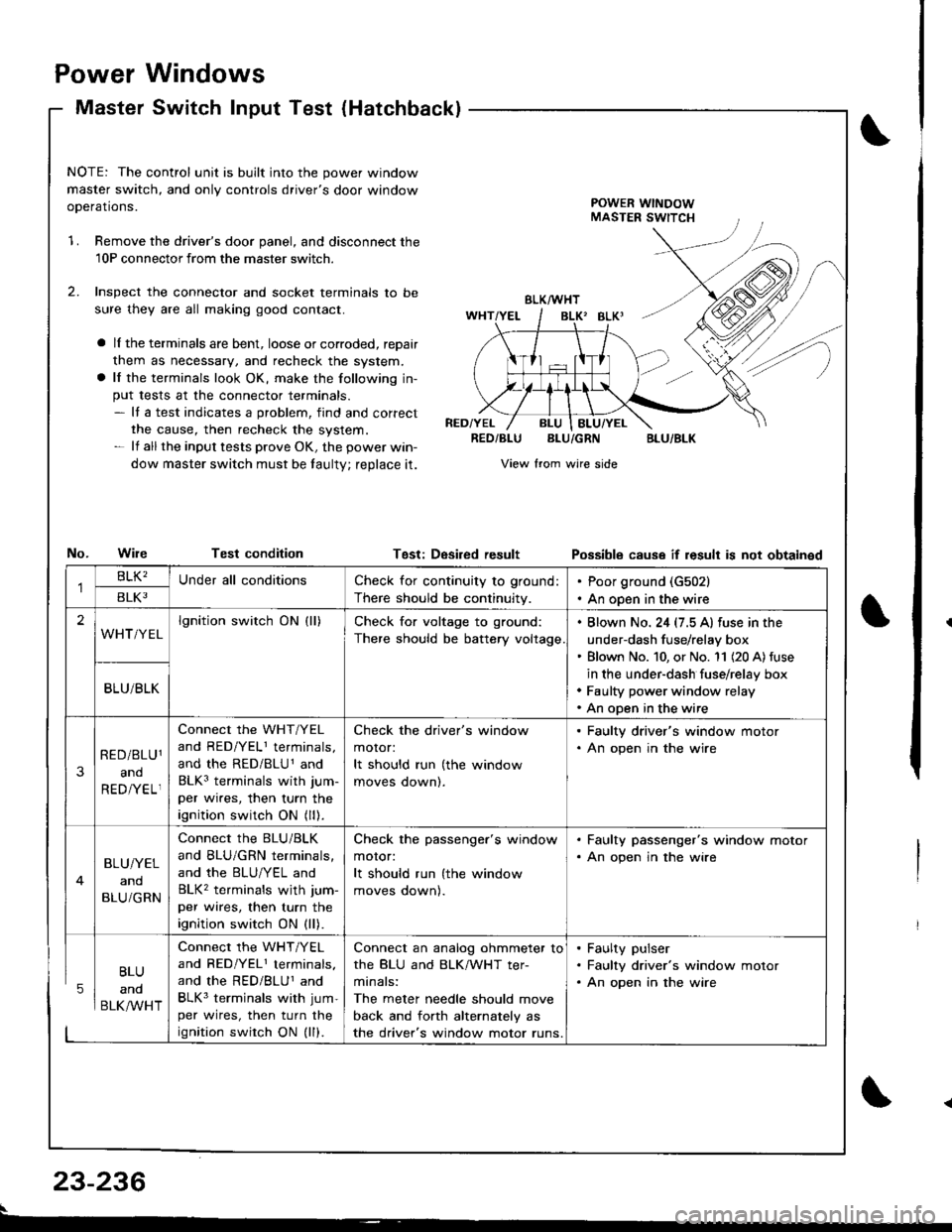
Power
Master
Windows
Switch Input Test (Hatchbackl
NOTE: The control unit is built into the power window
master switch, and only controls driver's door window
ooerations.POWER WINDOWMASTER SWITCH
1.Remove the driver's door panel, and disconnect the
10P connectorfrom the master switcn.
Inspect the connector and socket terminals to be
sure they are all making good contact.
a lI the terminals are bent, loose or corroded, reDair
them as necessary, and recheck the system.
a lf the terminals look OK, make the following in-
put tests at the connector terminals.- It a test indicates a problem, find and correct
the cause, then recheck the system.- lf all the input tests prove OK, the power win-
dow master switch must be taulty; reDlace it.
No.WileTest condition
BLK/WHT
BLK' BLKI
RED/YELRED/BLUBLU/GRNBLU/BLK
View from wire side
Tgst: DesiredresultPossibls cause if result is not obtainsd
BLU
and
BLK/WHT
Check for continuity to ground:
There should be continuity.
Poor ground (G502)
An open in the wire
lgnition switch ON (ll)Check for voltage to ground:
There should be battery voltage
. Blown No. 24 (7.5 A) fuse in the
under-dash fuse/relay box' Blown No. 10, or No. '11 (20 A) fuse
in the under-dash fuse/relay box. Faulty power window relay. An open in the wire
Connect the WHT/YEL
and RED/YELI terminals,
and the RED/BLU1 and
BLK3 terminals with jum-
per wires, then turn the
ignition switch ON (ll).
Check the driver's window
motor:
It should run (the window
moves oownl.
. Faulty driver's window motor. An open in the wire
Connect the BLU/BLK
and BLU/GRN terminals,
and the BLU/YEL and
BLK2 terminals wjth jum-
per wires, then turn the
ignition switch ON (ll).
Check the passenger's window
motor:
It should run (the window
moves oownl.
. Faulty passenger's window motor. An open jn the wire
Connect the WHT/YEL
and RED/YEL1 terminals.
and the RED/BLUI and
BLK3 terminals with jum-
per wires, then turn the
ignition swirch ON (ll).
Connect an analog ohmmeter to
the BLU and BLK/WHT ter-
minals:
The meter needle should move
back and forth alternately as
the driver's window motor runs.
. Faulty pulser. Faulty driver's window motor. An open in the wire
23-236
Page 1300 of 1681
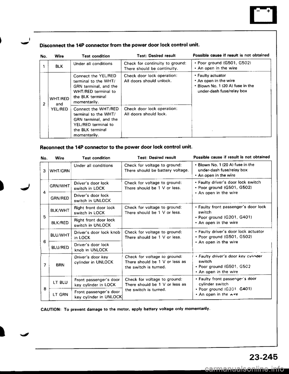
Disconnect the 14P connector from the power door lock control unit'
)
No. WileTest conditionTest: Dgsired resultPossible causo if rosult is not obtained
Reconnect the 14P conneetor to the power door lock control unit'
No. wireTest conditionTest: Desired resultPossible cause il result is not obtained
I
1BLKUnder all conditionsCheck tor continuity to ground:
There should be continuity.
. Poor ground (G50'1, G502). An open in the wire
2
WHTi RED
ano
YEL/RED
connect the YEL/RED
terminal to the WHT/
GBN terminal, and the
WHT/RED terminal to
the BLK terminal
momentarily.
Check door lock operation:
All doors should unlock.
Faulty actuator
An open in the wire
Blown No. 1 {20 A} fuse in the
under-dash Juse/relay box
Connect the WHT/RED
terminal to the WHT/
GRN terminal, and the
YEL/RED terminal to
the BLK terminal
momentanly.
Check door lock operation:
All doors should lock.
3WHT/GRN
Under all conditionsCheck for voltage to ground:
There should be battery voltage.
. Blown No. 1 (20 A) fuse in the
under-dash fuse/relay box. An open in the wire
GRN/WHTDriver's door lock
switch in LOCK
Check lor voltage to ground:
There should be 1 V or less.
Faulty driver's door lock switch
Poor ground (G501, G502)
An open in the wire
GRN/REDDriver's door lock
switch in UNLOCK
5
BLK/WHTRight front door lock
switch in LOCK
Check for voltage to ground:
There should be 1 V or less.
Faulty front passenger's door lock
switch
Poor ground (G201 , G401)
An open in the wireBLKi REDRight front door lock
switch in UNLOCK
BLU/WHTDriver's door lock knob
in LOCK
Check for voltage to ground:
There should be 1 V or less.
. Faulty driver's door lock actuator. Poor ground (G501, G502). An open in the wire
BLU/REDDriver's door lock
knob in UNLOCK
7BRN
Oriver's doo. key
cylinder in UNLOCK
Check for voltage to ground:
There should be 1 V or less as
the switch is turned.
. Faulty driver's door key cvtrrder
switch. Poor ground (G501, G502. An open in the wire
8
LT BLUFront passenger's door
key cylinder in LOCK
Check for voltage to ground:
There should be 1 V or less as
the switch is turned.
. Faulty front passengef's door
cylinder switch. poor ground lG20r G4Ol). An open in the *reLT GRNFront passenger's door
key cylinder in UNLOCK
\J
CAUTION: To prevent damage to the motol, apply battery voltage only momentarily
23-245
Page 1302 of 1681
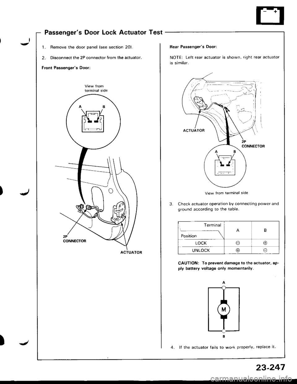
Passenger's Door Lock Actuator Test
1. Remove the door panel (see section 20).
2. Disconnect the 2P connector from the actuator.
Front Passenger's Door:
lerminal side
ACTUATOR
)J
23-247
Rear Passenger's Door:
NOTE: Left rear actuator is shown, right rear actuator
is similar.
View from lerminal side
Check actuator operation by connecting power and
ground according to the table.
CAUTION: To prevent damage to the actuator, ap-
ply battery voltage only momenta.ily.
;
4. lf the actuator tails to work properly, replace it.
Term inal
Position
B
LOCKo@
UNLOCKoo
Page 1305 of 1681
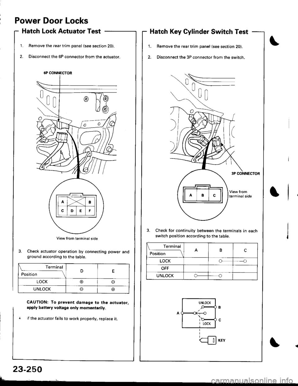
Power Door Locks
Hatch Lock Actuator Test
Remove the rear t.im panel (see section 20).
Disconnect the 6P connector from the actuator.
1.1.
2.
Hatch Key Cylinder Switch Test
Remove the rear trim panel (see section 20).
Disconnect the 3P connector from the switch.
3. Check for continuitv between the terminals in each
switch position according to the table.
6P CONNECTOR
3. Check actuator operation by connecting power andground according to the table.
CAUTION: To prev€nt damage to the actuator,
apply battery voltage only momeniarily.
1 lf the actuator fails to work properly, replace it,
23-250
Terminal
ilil;---tBc
LOCKoo
UNLOCKo
Terminal
ilil;-]E
LOCK@o
UNLOCKoo
UNLOCK
.-,4
I LOCK
| !J KEY
Page 1307 of 1681
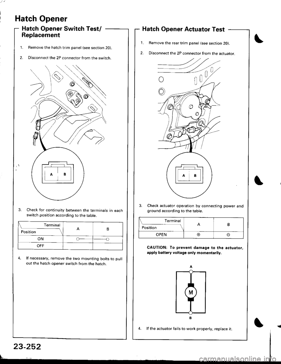
Hatch Opener
Hatch Opener Switch Test/
Replacement
Remove the hatch trim panel (see section 20).
Disconnect the 2P connector from the switch.
3. Check for continuity between the terminals in eachswatch position according to the table.
4. lf necessary, remove the two mounting bolts to pull
out the hatch opener switch from the hatch.
1.
2.
1.
2.
Hatch Opener Actuator Test
Remove the rear trim panel (see section 20).
Disconnect the 2P connector from the actuator.
3. Check actuator operation by connecting power andground according to the table.
CAUTION: To prevent damage to the actuator,
apply battery voltage only momentarily.
Terminal
PositionB
ONo
OFF
Terminal
PositionB
OPEN@o
23-252
4. lf the actuator fails to work properly, replace it.{
Page 1313 of 1681
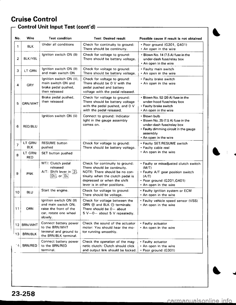
Cruise Control
- Control Unit InputTest(cont'dl
IBLKUnder all conditionsCheck for continuity to ground:
There should be continuity.
. Poor ground (G20l, G401). An open in the wire
2BLK/YEL
lgnition switch ON {ll}Check for voltage to ground:
There should be battery voltage.
. Blown No. l4 (7.5 Alfuse in the
under-dash fuse/relay box. An open in the wire
3LT GRNlgnition switch ON (ll)
and main switch ON
Check for voltage to ground:
There should be battery voltage.
. Faulty main swjtch. An open in the wire
GRY
lgnition switch ON (ll),
main switch ON and
brake pedal pushed,
then released
Check for voltage to ground:
There should be O V with the
pedal pushed and battery
voltage with the pedal released.
. Faulty brake switch. An open in the wire
5GRN/WHT
Brake pedal pushed,
then released
Check for voltage to ground:
There should be battery voltage
with the pedal pushed, and 0 V
with the pedal released.
Blown No. 52 (20 A)fuse in the
under-hood fuse/relay box
Faulty brake switch
An open in the wire
6RED/BLU
lgnition switch ON (ll)Connect to ground: lndicator
light in the gauge assembly
comes on.
Blown bulb
Blown No. 25 (7.5 A)fuse in the
under-dash fuse/relay box
Faulty dimming circuit in the gauge
assembly
An open in the wire
7LT GRN/
BLK
RESUME button
pushed
Check tor voltage to ground:
There should be battery voltage.
Faulty SET/RESUME switch
Faulty cable reel
An open in the wire8LT GRN/
RED
SET button pushed
IPNK
MT/: Clutch pedal
released
A/Tr Shift lever in [2l,
[Dl]. o, [o'l
-
Check for continuity to ground:
There should be continuity.
NOTE: There should be no con-
tinuity when the clutch pedal is
depressed or when the shift
lever is in other positions.
Faulty or misadjusted clutch switch(M/T)
Faulty A/T gear position switch(A/T)
Poor ground (G201,G401)
An open in the wire
't0BLUStart the engine.Check lor voltage to ground:
There should be voltage.
. Faulty ignition system or ECM. An open in the wire
't1ORN
lgnition switch ON (ll)
and main switch ON;
raase the front of the
car, rotate one wheel
slowly.
Check for voltage between the
ORN @ and BLK O terminals:
There should be 0- about
5 V-O- about 5 V repeatedly.
. Faulty vehicle speed sensor {VSS). An open in the wire
BRN/WHTConnect battery power
to the BRN/WHT
terminal and ground to
the BRN/BLK terminal.
Check the sound of the actuator
motor: You should hear the mo-
tor running smoothly.
. Faulty actuator. An open in the wire
BRNi BLK
Connect battery power
to the BRN/RED
Iermrnal.
Check the operation of the mag-
netic clutch: Clutch should click
and output link should be locked.
Faulty actuator
An open in the wire
Poor ground (G30'l)
No. Wire Test conditionTest: Desiled result Possible cause il lesult is not obtained
' 4 I BRN/RED
{
{
23-258
-L
Page 1314 of 1681
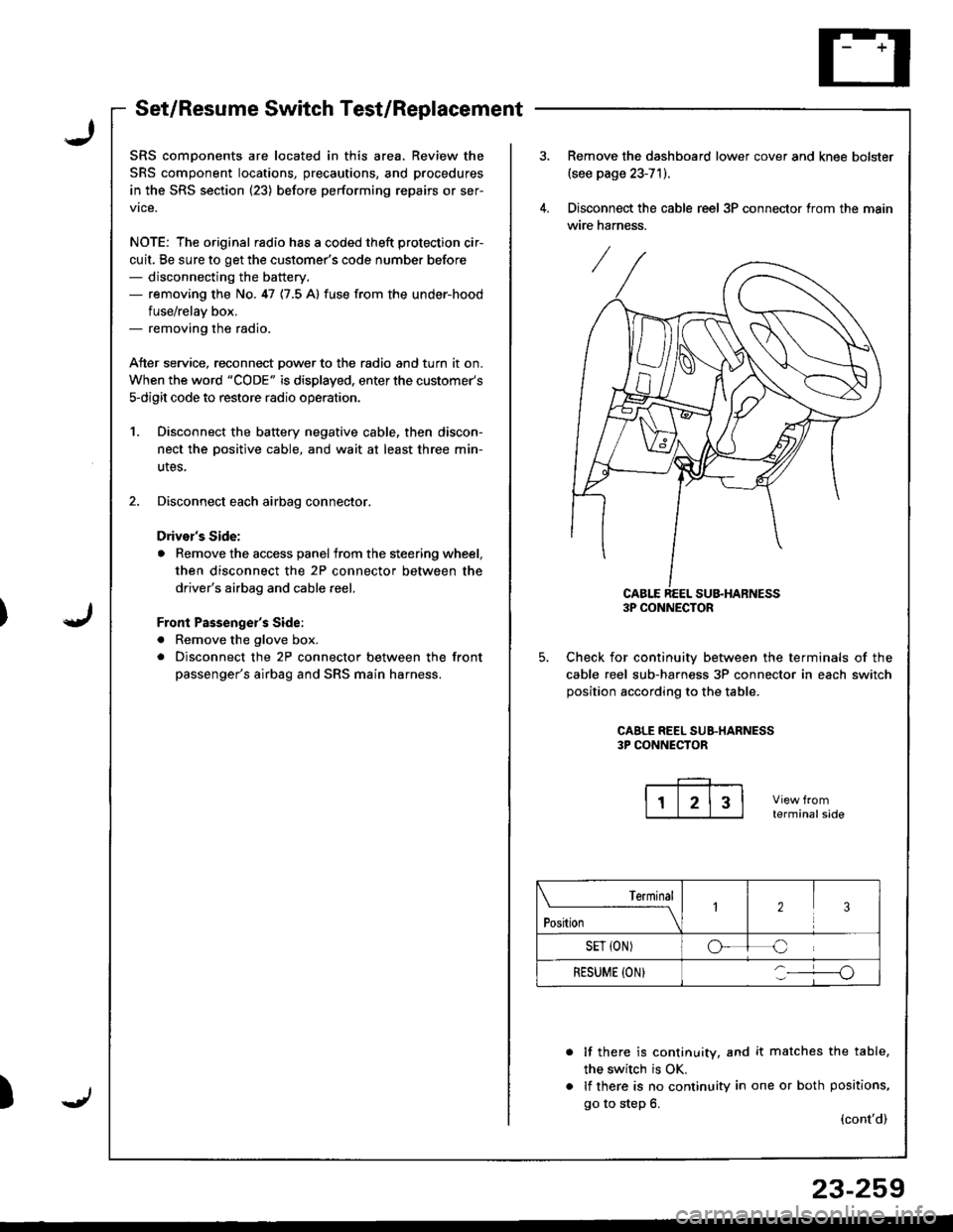
Set/Resume Switch Test/Replacement
SRS comDonents are located in this area. Review the
SRS component locations, precautions, and procedures
in the SRS section (23) before performing repairs or ser-
vice.
NOTE: The original radio has a coded theft protection cir-
cuit, Be sure to get the customer's code number before- disconnecting the battery.- removing the No. 47 {7.5 A} fuse from the under-hood
fuse/relav box.- removing the radio.
Atter service, reconnect Dower to the radio and turn it on.
When the word "CODE" is displayed, enter the customer's
s-digit code to restore radio operatior..
1. Disconnect the battery negative cable, then discon-
nect the oositive cable, and wait at least three min-
utes,
2. Disconnect each airbag connector.
Drivor's Side:
a Remove the access panel from the steering wheel,
then disconnect the 2P connector between the
driver's airbag and cable reel,
Front Passenge;'s Side:
a Remove the glove box.
. Disconnect the 2P connector between the front
passenger's airbag and SRS main harness.
)
Remove the dashboard lower cover and knee bolster(see page 23-71).
Disconnect the cable reel 3P connector trom the main
wire harness.
CABLE REEL SU&HARNESS3P CONNECTOR
Check for continuiw between the terminals of the
cable reel sub-harness 3P connector in each switch
position according to the table.
CAALE REEL SUB.HARNESS3P CONNECTOR
terminalside
lf there is continuity, and it matches the table,
the switch is OK.
lf there is no continuity in one or both positions,
go to step 6.(cont'd)
Terminal
t"*-
---\23
SET {ON)oC
RESUME (ON}o
23-259
Page 1315 of 1681
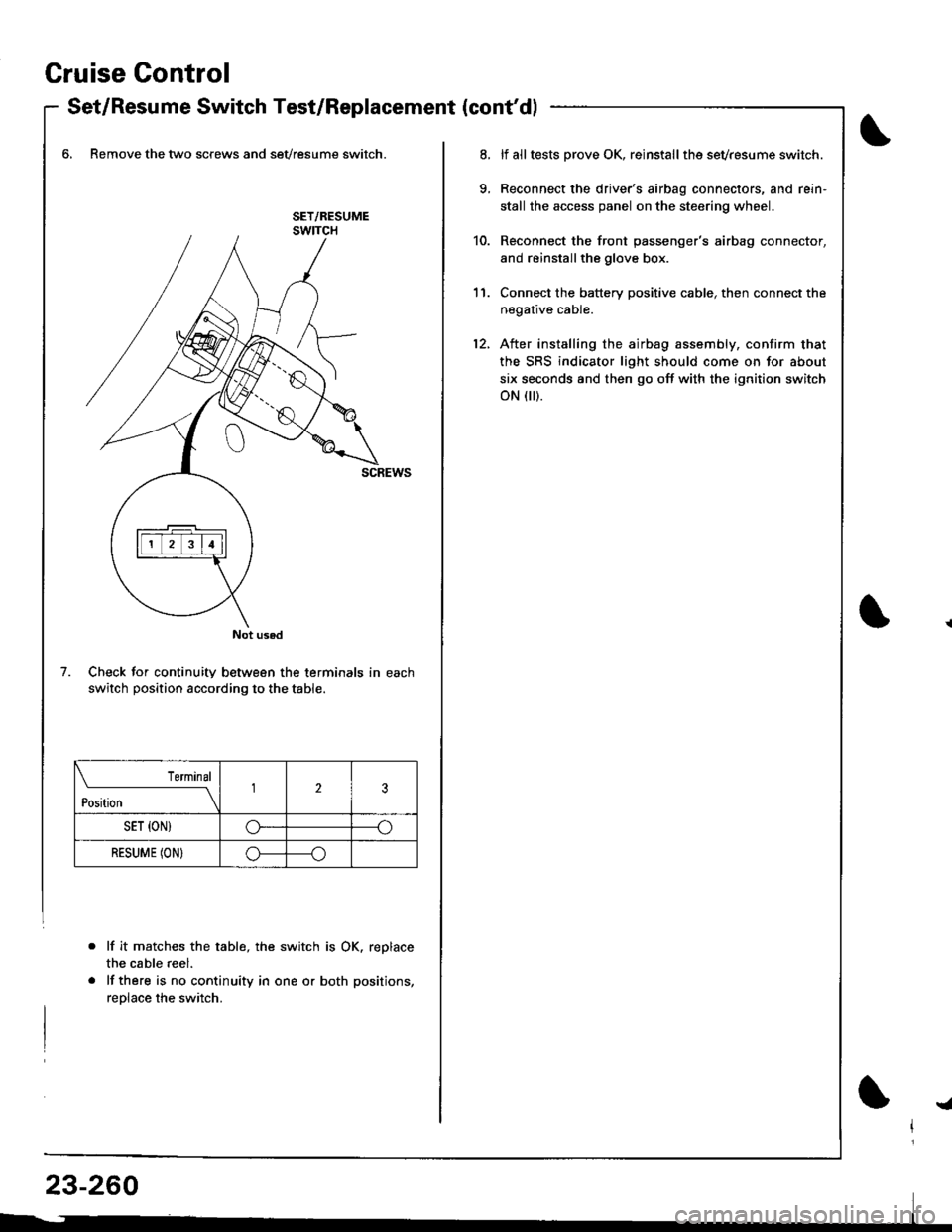
Gruise Control
- Set/Resume Switch Test/Replacement {cont'dl
6, Remove the two screws and sevresume switch.
Check for continuity between the terminals in each
switch position according to the table.
lf it matche$ the table, the switch is OK. replace
the cable reel.
lf there is no continuity in one or both positions,
reolace the switch.
Not used
7.
Terminal
t*n*------l23
SET {ON)G----o
RESUME (ON}o----o
lf alltests prove OK, reinstallthe sevresume switch.
Reconnect the driver's airbag connectors, and rein'
stall the access panel on the steering wheel.
Reconnect the front passenger's airbag connector,
and reinstallthe glove box.
Connect the battery positive cable, then connect the
negative cable.
After installing the airbag assembly, confirm that
the SRS indicator light should come on for about
six seconds and then go off with the ignition switch
oN flr).
11.
12.
!a
Page 1319 of 1681
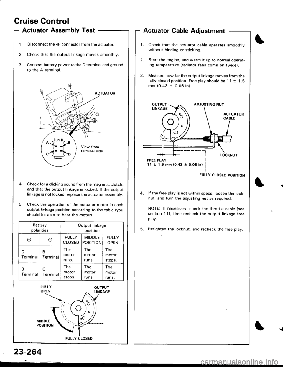
Cruise Gontrol
1.
Actuatol Assembly Test
Disconnect the 4P connector from the actuator.
Check that the output linkage moves smoothly.
Connect battery power to the D terminal and ground
to the A terminal.
ACTUATOR
Check tor a clicking sound from the magnetic clutch.
and that the output linkage is locked. lf the outputlinkage is not locked, replace the actuator assembly.
Check the operation of the actuator moror In eacn
output linkage position according to the table (you
should be able to hear the motor).
FULLY CLOS€D
2.
3.
3.
23-264
Actuator Cable Adjustment
Check that the actuator cable operates smoothly
without binding or sticking.
Start the engine, and warm it up to normal operat-
ing temperature (radiator fans come on twice).
Measure how far the output linkage moves from thefully closed position. Free play should be 11 t 1,5mm (0.43 t 0.06 in).
FREE PLAY:1M.5 mm (0.43 1 0.06 in)
FULLY CLOSED POSITTON
4. lf the free play is not within specs, loosen the lock-
nut, and turn the adjusting nut as required.
NOTE: It necessary, check the throttle cable (see
section 1 1), then recheck the output linkage lreeplay.
5. Retighten the locknut, and recheck the free play.
^ffi"
c17i l,io
Battery
polaritiesOutput linkage
position
ooFULLY
CLOSED
MIDDLE
POSITION
FULLY
OPEN
c
Terminal
B
Terminal
The
moror
runs.
The
molor
runs.
The
motor
stops.
B
Terminal
c
Terminal
The
motor
stops.
The
motor
runs.
The
motor
runs.
{