battery HONDA INTEGRA 1998 4.G Manual Online
[x] Cancel search | Manufacturer: HONDA, Model Year: 1998, Model line: INTEGRA, Model: HONDA INTEGRA 1998 4.GPages: 1681, PDF Size: 54.22 MB
Page 1135 of 1681
Starting System
Starter Test (cont'dl
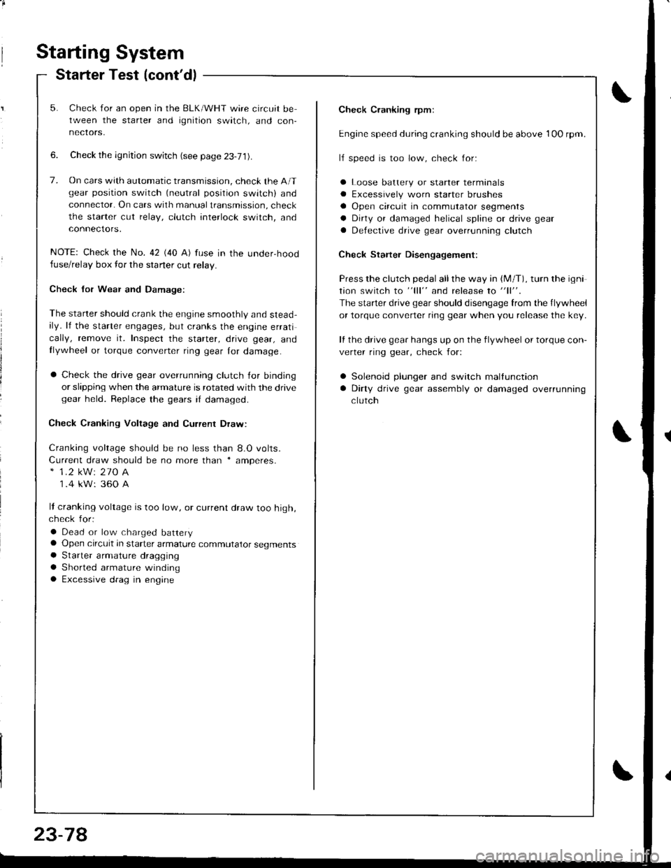
Check Cranking rpmr
Engine speed during cranking should be above 1OO rpm.
lJ speed is too low, check for:
a Loose batlery or starter terminals
a Excessively worn starter brushes
a Open circuit in commutator segments
a Dirty or damaged helical spline or drive gear
a Defective drive gear overrunning clutch
Check Starter Disengagement:
Press the clutch pedal all the way in (M/T), turn rhe igni
tion switch to "lll" and release to "11".
The starter drive gear should disengage from the flywheel
or torque converter ring gear when you release the key.
It the drive gear hangs up on the flywheel or torque con-
verter ring gear, check for:
a Solenoid plunger and switch mallunction
a Dirty drive gear assembly or damaged overrunning
clutch
5. Check for an open in the BLK/WHT wire circuit be
tween the starter and ignition switch, and con-
necrors,
6. Check the ignition switch (see page 23-71).
7. On cars with automatic transmission, check the A/Tgear position switch (neutral position switch) and
connector. On cars with manualtransmission, check
the starter cut relay, clutch interlock switch, and
connectors.
NOTE: Check the No. 42 (40 A) fuse in the under,hoodfuse/relay box for the starter cut relay.
Check Jor Wear and Damage:
The starter should crank the engine smoothly and stead,ily. lf the starter engages, but cranks the engine errati
cally, remove it. Inspect the starter, drive gear, andllywheel or torque converter ring gear lor damage.
a Check the drive gear overrunning clutch for binding
or slipping when the armature is rotated with the drivegear held. Replace the gears i{ damaged.
Check CJanking Voltage and Current Draw:
Cranking voltage should be no less than 8.O volts.
Current draw should be no more than * amperes.* 1.2 kW: 27O A
1 .4 kW: 360 A
It cranking voltage is too low, or current draw too high,check for:
a Dead or low charged batterya Open circuit in starter armature commutator segmentsa Starter armalure dragging
a Shorted armature windinga Excessive drag in engine
Page 1137 of 1681
Starting System
Starter Replacement
NOTE: The original radio has a coded theft protection
citcuit. Be sure to get the customer's code number before- disconnecting the battery.- removing the No. 47 {7.5 A) fuse from the under-hood
fuse/rslav box.- removing the radio.
After service, reconnect power to the radio and turn it
on. When the word "CODE" is displayed. enter the cus-
tomer's 5-digit code to restore radio operation.
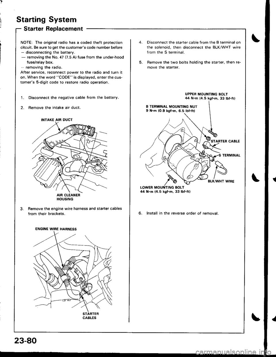
Disconnect the negative cable trom the battery.
Remove the intake air duct.
AIR CLEANERHOUSING
R€move the engine wire harness and starter cables
from their brackets.
1.
3.
INTAKE AIR DUCT
ENGINE WIRE HARNESS
CABLES
23-80
5.
Disconnect the starter cable from the B terminal on
rhe solenoid, then disconnect the BLK/WHT wire
from the S terminal.
Remove the two bolts holding the starter, then re-
move the starter.
UPPER MOUNTING BOLT44 N.m (4.5 kgf.m, 33 lbt.fr)
STARTER CABLE
TERMINAL
BLK/WHT WIRE
6. Install in the reverse order of removal.
Page 1144 of 1681
J
Starting System
Performance Test
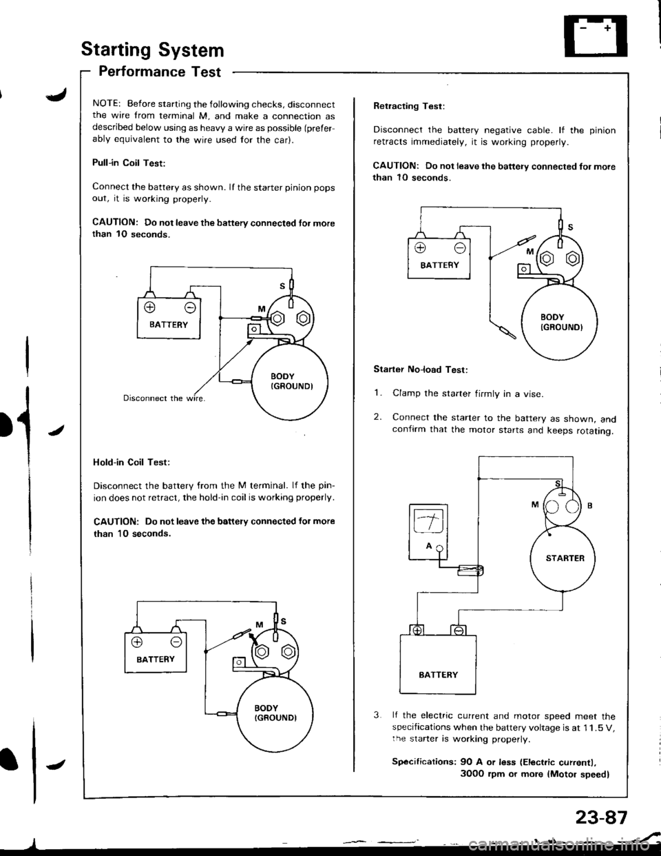
NOTE: Before starting the following checks, disconnectthe wire from terminal M, and make a connection asdescribed below using as heavy a wire as possible (prefer
ably equivalent to the wire used for the car).
Pull-in Coil Test:
Connect the battery as shown. If the starter pinion pops
out, it is working properly.
CAUTION: Do not leave the battery connectsd Jor morethan 1O seconds.
Hold-in Coil Test:
Disconnect the battery from the M terminal. lf the pin-
ion does not retract, the hold-in coil is working properly.
CAUTION: Do not leave the battery connected for more
than 10 seconds.
J
Retracting Test:
Disconnect the battery negative cable. lf the pinion
retracts immediately, it is working properly.
CAUTION: Do not leave the battery connected fol more
than 1O seconds.
Starter No]oad Test:
1. Clamp the starter firmly in a vise.
2. Connect the starter to the battery as shown, andconfirm that the motor starts and keeps rotating.
3 lf the electric current and motor soeed meet thespecifications when the battery voltage is at 1 1.5 V,the starter is working properly.
Sp€cifications: 9O A or less (Electric currentl,
3O0O rpm or more {Motor speed}
Page 1154 of 1681
lgnition Control Module (lCM) Input Test
NOTE:
a See section 1 1 if the malfunction indicator lamp (MlLl
has been reported on.a Perform an input test for the ignition control module(lCM) after finishing the fundamental tests for the ig-nition system and the fuel and emissions systems.a The tachometer should operate normally.
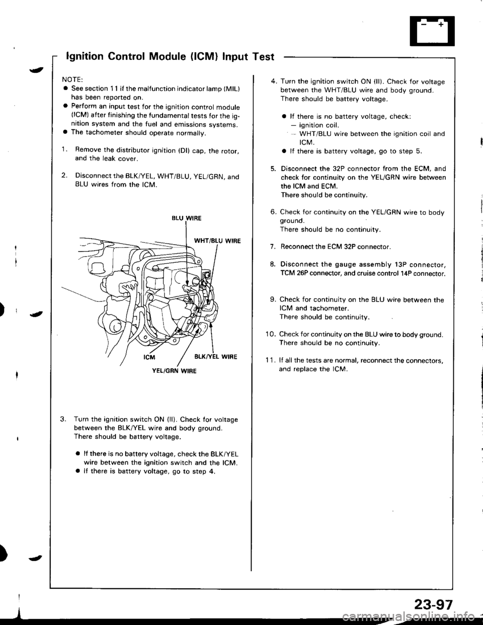
1. Remove the distributo. ignition (Dl) cap, the rotor,and the leak cover.
2. Disconnect the BLK/YEL, WHT/BLU, YEL/GRN, andBLU wires from the lCM.
3. Turn the ignition switch ON {ll}. Check for voltage
between the BLK/YEL wire and body ground.
There should be battery voltage.
a lf there is no battery voltage, check the BLKiYEL
wire between the ignition switch and the lCM.a It there is battery voltage, go to step 4,
)
I
)
BLU WIRE
YEL/GRN I,\'IRE
4. Turn the ignition switch ON (ll). Check for voltage
between the WHT/BLU wire and body ground.
There should be battery voltage.
a lf there is no battery voltage, check:- ignition coil.- WHT/BLU wire between the ignition coil and
tcM.
a lf there is battery voltage, go to step 5.
5. Disconnect the 32P connector from the ECM, and
check for continuity on the YEUGRN wire between
the ICM and ECM.
There should be continuity.
6. Check for continuity on the YEL/GRN wire to bodygrouno.
There should be no continuity.
7.Reconnect the ECM 32P connector.
Disconnect the gauge assembly 13P connector,
TCM 26P connector, and cruise control l4P connector.
9. Check for continuity on the BLU wire between the
ICM and tachometer.
There should be continuity.
'10. Check for continuity on the BLU wire to body ground.
There should be no continuity.
1 1 . lf all the tests are normal, reconnect the connectors,
and replace the lCM.
23-97
/i
Page 1156 of 1681

)
)
Charging System
Component Locationlndex
CHARGING SYSTEM LIGHT(ln the gauge assembly)Test, pages 23-102,103Bulb Locations, page 23-122
UNDER-HOOD FUSE/RELAY BOX(USA: HAS bUiIt-iN ELECTRICALLOAD DETECTOR (ELD) UNIT}Troubleshooting of ELD, secrion 11
BATTERYTest,
ALTERNATOR BELTInsp€ction and Adiustment, page 23_115ALTERNATORTroubleshooting, page 23'102Alternator/FegulatorTosl, pages 23-105,'106Replacement, page 107Overhaul, page 23-108
23-99
.t-
Page 1159 of 1681
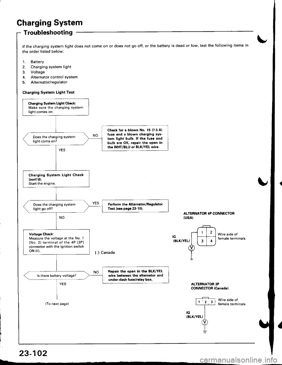
Charging System
Troubleshooting
It the charging system light does not come on or does not go off, or the battery is dead or low, test the following items in
the order listed below:
1. Battery
2. Charging system light
3. Voltage
4. Alternator control system
5. Alternator/regulator
Charging System Light Test
ALTERNATOR'P CONNECTORIUSAI
IGIBLK/YEL)
Wire side offemale terminals
Wire side offemale terminals
ALTERNATOR 3PCONNECTOR lCanadal
Charging System Light Check:Make sure the charging systemlight comes on.
Ch€ck tor a blown No. 15 (7.5 A)
tuse and . blown charging sys-
tem light bulb. ll the fuse andbulb are OK, .eptir tho open inlhe WHT/BLU or BLK/YEL wire.
Does the charging systemlight come on?
Ch.rging System Light Check(cont'd):
Start the engine.
Pertorm the Ahernator/RegulstolTest (s€. prge 23-101,Does the charging systemlight go off?
Voltago Check:Measure the voltage at the No. 1
lNo. 2l terminal of the 4P [3P]connector with tho ignition switchoN {lr).
Repair tho open in ih€ 8LK/YELwir6 betweon the alte]nator andundor-dash lure/reley box.
I4
L-*
23-102
Page 1161 of 1681
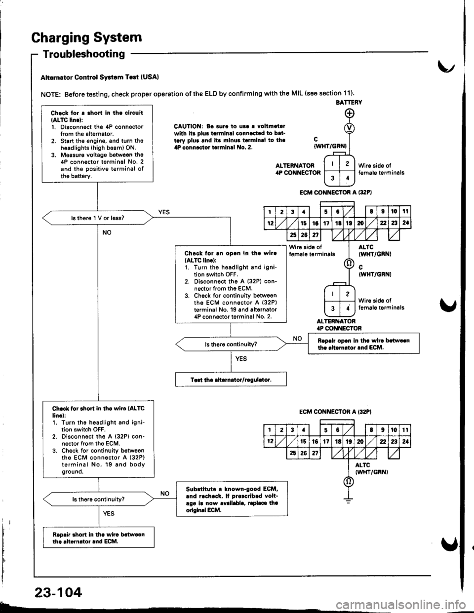
Gharging System
Troubleshooting
Ahcrn.tor Control Swtom T.rt (USA)
NOTE: Betore testing, check proper operation of the ELD by confirming with the MIL (s€e section 11).
CAUTION: Ba 3urc to ut! | vollmatalwith hr plu! tarmlnal connactad to bat-tary plua and ita mlnua talmlnal to lha4P connactor tarrninal No. 2.
ALTENNATORilP COiINECTOR
cIWHT/GBN}
ALTERNATOR.P CONI{ECTOB
Wire sido olt€m6le t€rminal6
ECM CONI{ECTOR A l:t2F)
BATTERY
Ch.ck tor . .hort In th. clrcuit(ALTC ltn.lr1. Disconnect the 4P connoctorIrom th6 altemator.2. Start tho engine, and turn thoh6adlights (high beam) ON.3. Moasur€ voltago botwoen th64P conn€ctor t6rminal No. 2and the positivo t€rminsl oltho batterv.
16 thor6 1 V or less?
Chrck for .n oD.n In th. wllrIALTC lln.):1. turn the headlight and igni-tion switch OFF.2. Disconnect th6 A (32P) con-noctor from the ECM.3. Ch6ck for continuity b6tw6entho ECM connoctor A (32P)
t€rminal No, 19 and alternator4P connoctor torminal No. 2.
Rrp.h op.n In th. wh. brlw..nth. rltarn oi.nd ECM.
Ch.ct for rhort in th. wire (ALTC
lin.l:'1. Turn the headlight and ignition switch OFF.2. Disconn€ct the A {32P} con-n6ctor from tho ECM.3. Check for conlinuity b€twoenths ECM connector A (32P)
terminal No. 19 8nd bodyground.
Slbrlltut. ! tnown-good ECM..nd rach.ck. It Drorcrlb.d volt-rgr ir now avalldla, raphce lhaorigin.l Ecilt.
Rap.ir 3hort in lha wira bstwaanth. .h.rnator ard ECI\|.
I23{5GtI|l0tl
72151aItIt136zla2a
a26n,/,V
Wir€ side offem6le t€rminals(l
ALTC(wl{T/GRNI
cIWHT/GBNI
Wire 3id€ offemal6 t€rminelg34
ECM CONNECTON A I32P}
t23a50t9t0tt
12t510l1Itt9mz2a2a
62621
ALTCIWHT/GRNI()
23-104
b-.
Page 1162 of 1681
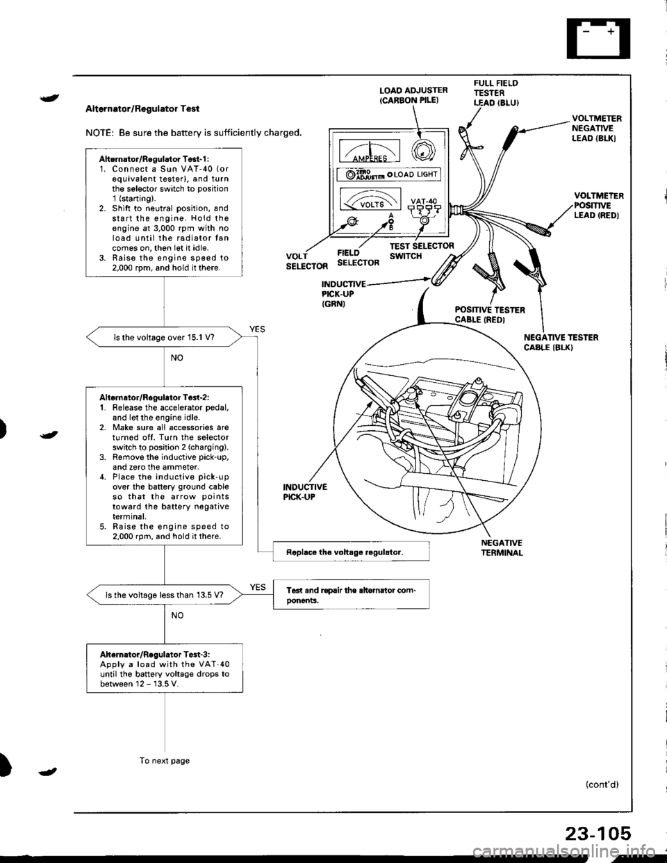
{
t
Alternator/Regulator Test
NOTE: 8e sure the battery is sufficiently charged.
LOAO ADJUSTER
ICARBON PILE)
FULL FIELDTESTERT.EAD (8LU)
POSITIVE TESTERCABLE IREDI
NEGATIVETERMINAL
VOLTMETERNEGATIVELEAO {BL|(}
VOLTMEIERPOSmVELEAD IREDI
FIELOSELECTOR
TEST SELECTORswtTcHVOLTSELECTOR
INDUCTIVEPICK.UP
INDUCTIVEPICK.UPIGRNI
NEGANVE TESTERCABLE IBLKI
)
)
{cont'd)
23-105
Ahernator/Regulator Tosl-1 :1. Connect a Sun VAT-40 (or
equivalent testerl, and turnthe selector switch to position'1 (starting).
2. Shift to neutral position, andstart the engine. Hold theengine at 3,000 rpm with noload until the radiator tancomes on, thon let it idle.3. Raise the engine sp€ed to2,000 rpm, and hold it there.
ls the voltage over 15.1 V?
Altsrnator/Rogulator Test-z:1. Release the accelerator pedal,
and let the engine idle.2, Make sure all accessories areturnod off. Turn the selectorswitch to position 2 (charging).
3. Remove the inductive pick-up,
and zero the ammeter.4. Place the inductive pick-up
over the battery ground cableso that the arrow points
toward the batterY negativeterminal,5. Raise the engine speed to2.000 rpm, and hold it there.
ls the voltage less than 13.5 V?
Ahelnstor/Regulator T$t-3iApply a load with the VAT-40until the battery voltage drops tobetween 12 - 13.5 V.
To next page
-
i-
Page 1164 of 1681
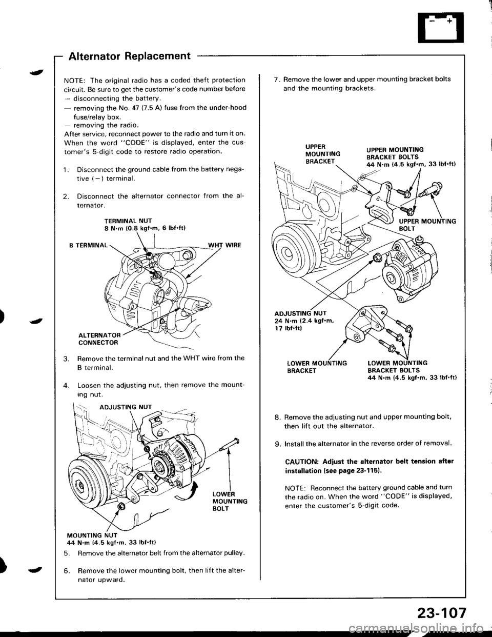
Alternator Replacement
)
t
-
NOTE: The original radio has a coded theft protection
circuit. Be sure to get the customer's code number before
- disconnecting the battery.
- removing the No. 47 (7.5 A) fuse from the under-hood
fuse/relay box.
removing the radio.
After service, reconnect power to the radio and turn it on.
When the word "CODE" is displayed, enter the cus
tomer's s-digit code to restore radio operation.
1. Disconnect the ground cable from the battery nega-
tive (- ) terminal.
2. Disconnect the alternator connector from the al-
lernalor,
TERMINAL NUT8 N,m (O.8 kgf'm, 6 lbl'ft)
B TERMINAL
ALTERNATORCONNECTOR
Remove the terminal nut and the WHT wire from the
B terminal.
Loosen the adjusting nut, then remove the mount-
Ing nut.
MOUNTINGBOLT
MOUNTING NUT44 N.m (4.5 kgf.m.33 lbt.ftl
5. Remove the alternator belt from the alternator pulley.
6. Remove the lower mounting bolt, then lilt the alter-
naror upwaro.
3.
{--,
7.Remove the lower and upper mounting bracket bolts
and the mounting brackets.
BRACKET BOLTSil4 N.m {4.5 kgl.m, 33 lbt.ft)
8. Remove the adiusting nut and upper mounting bolt,
then lift out the alternator.
9. lnstallthe alternator in the reverse order of removal.
CAUTION: Adiust the alternator belt tension aftsr
installation lseo page 23-1151.
NOTE: Reconnect the battery ground cable and turn
the radio on. When the word "CODE" is displayed,
enter the customer's s-digit code.
BRACKET
UPPER MOUNTINGBRACKET EOLTS44 N.m {4.5 kgl.m, 33 lbl'ft)
24 N.m (2.4 kgf.m,17 rbf.ftl
b-h..K
) I
23-107
-
,-
Page 1176 of 1681
)
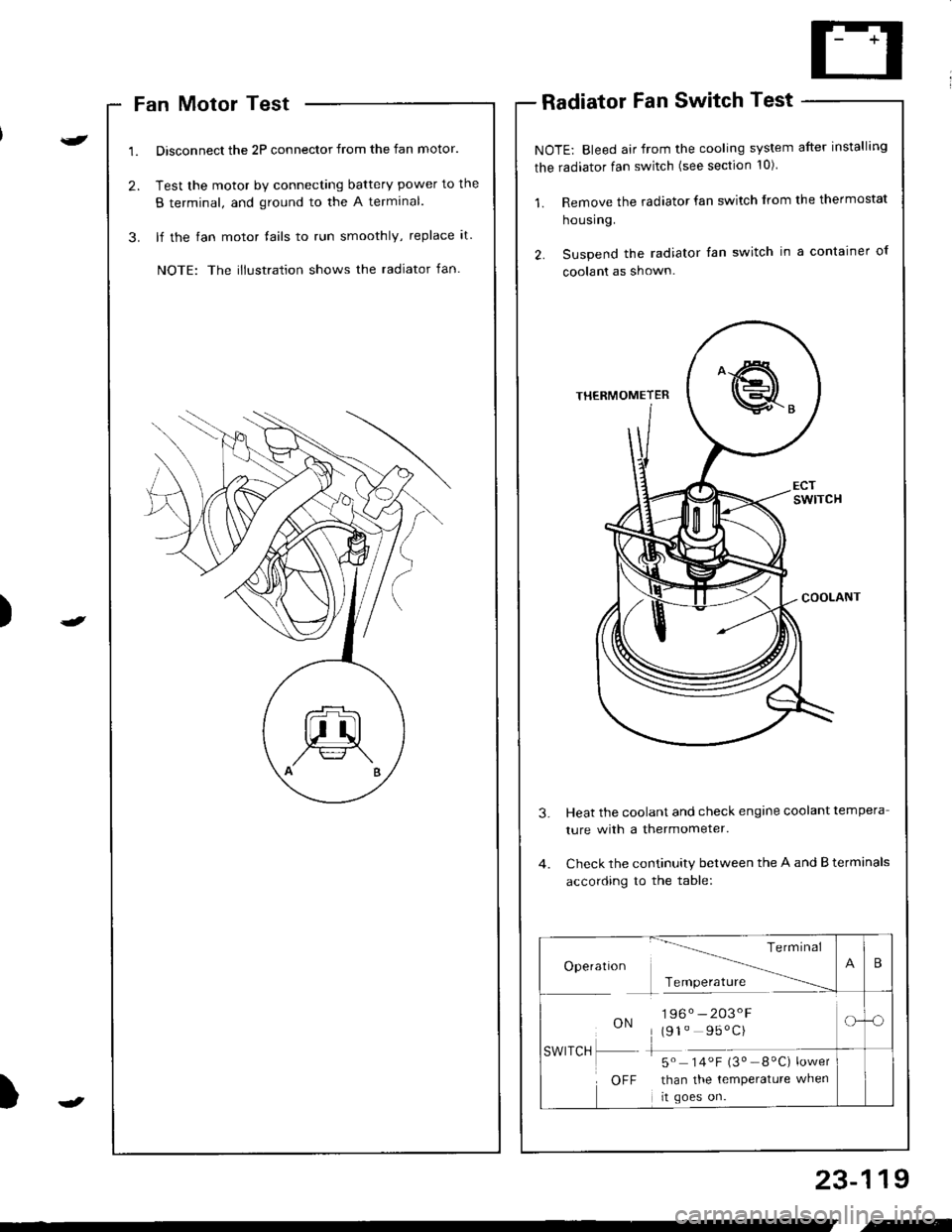
Fan Motor Test
Disconnect the 2P connector from the fan motor.
Test the motor by connecting battery power to the
B terminal, and ground to the A termlnal.
lf the fan motor fails to run smoothly, replace it.
NOTE: The illustration shows the radiator fan.
Radiator Fan Switch Test
NOTE: Bleed air from the cooling system after installing
the radiator fan switch (see section 10)
1. Remove the radiator fan switch from the thermostat
housing.
2. Suspend the radiator fan switch in a container ol
coolanl as shown.
Heat the coolant and check engine coolant tempera
ture with a thermometer.
Check the continuity between the A and B terminals
according to the table:
23-119
Te rm Inal
Operatlon -------\
Tcmoerature ------
ON196. -203'F
(91" 95'C)
-5" 14.F i3" _8"C) ;*,*
than the temperature when
rt goes on.
SWITCH
OFF
B
-o
.-