indicator HONDA INTEGRA 1998 4.G Workshop Manual
[x] Cancel search | Manufacturer: HONDA, Model Year: 1998, Model line: INTEGRA, Model: HONDA INTEGRA 1998 4.GPages: 1681, PDF Size: 54.22 MB
Page 156 of 1681
Grankshaft
Removal (cont'dl
Use the wooden handle ot a hammer to drive the
pistons out.
CAUTION:
. Take care not to damage the contact surface ot
the metal gasket.
. When removing the piston/connecting rod, take
care not to hit the oil iet (818C1, 818C5 enginesl.
. ll the oil iet nozzle is damaged or bent, replace
the oil iet assembly {818C1, B18C5 engincs.
page 8-9).
Reinstall the rod bearings and caps after removing
each piston/connecting rod assembly.
l\4ark each piston/connecting rod assembly with its
cylinder number to avoid mixup on reassembly.
NOTE; The existing number on the connecting rod
does not indicate its position in the engine, it indi-
cates the rod bore size.
End Play
NOTE: End play should be inspected before removing
crankshaft.
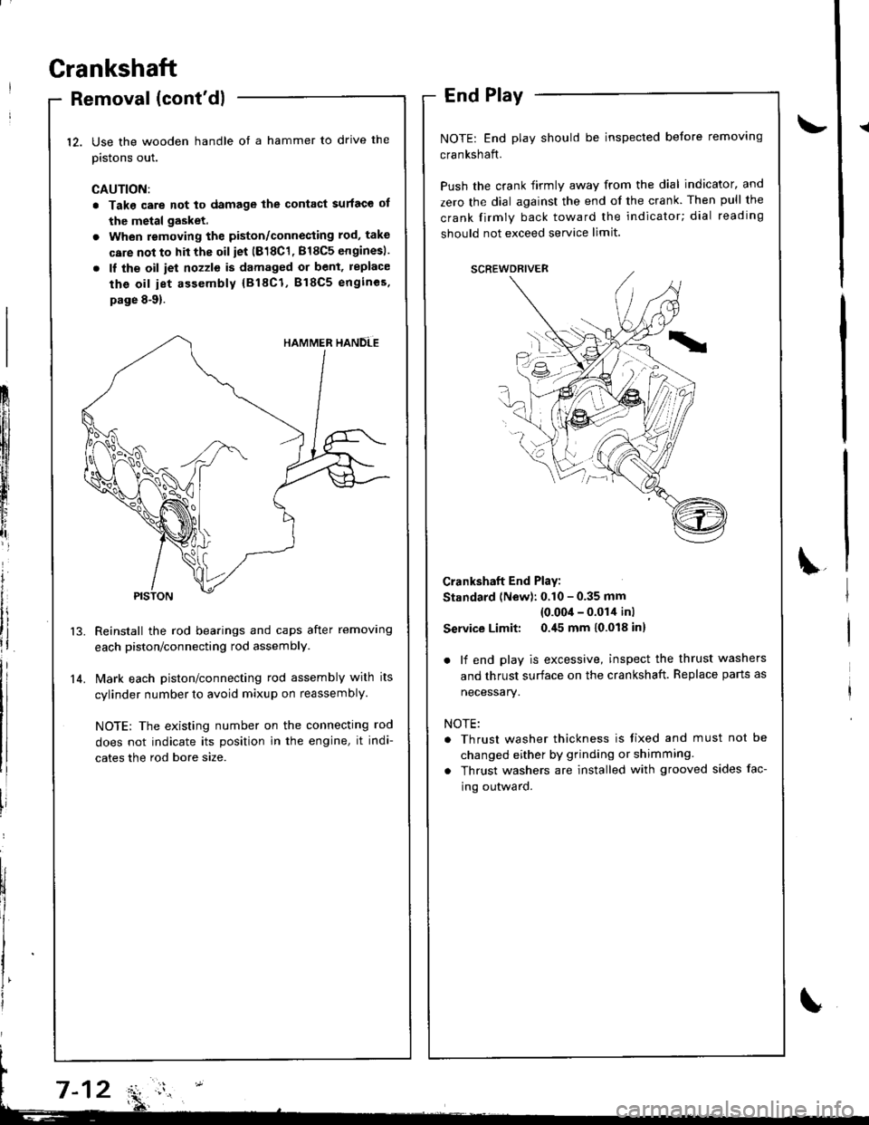
Push the crank firmly away from the dial indicator, and
zero the dial against the end of the crank. Then pull the
crank firmly back toward the indicator; dial reading
should not exceed service limit.
Crankshaft End Play:
Standard (New): 0.10 - 0.35 mm
{0.00'l - 0.014 inl
Service Limit: 0.45 mm 10.018 inl
. lf end play is excessive, inspect the thrust washers
and thrust surface on the crankshaft. Replace parts as
necessary.
NOTE:
. Thrust washer thickness is tixed and must not be
changed either by grinding or shimming.
. Thrust washers are installed with grooved sides fac-
ing outward.
12.
14.
Frlfll
ftl
t
iffi[l
t,,tlr
lt
i
Page 157 of 1681
NOTE:
. Clean the crankshaft oil passages with pipe cleanersor a suitable brush.
. Check the keyway and threads.
Alignment
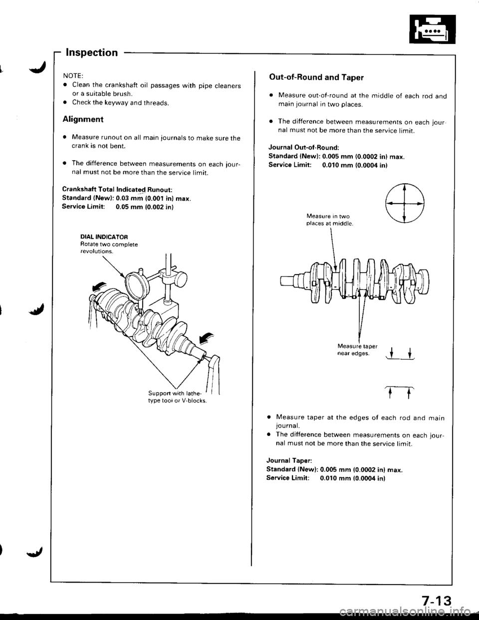
. Measure runout on all main journals to make sure thecrank as not bent.
. The difference between measurements on each ,our-nal must not be more than the service limit.
Crankshaft Total Indicated Runout:
Standard (New): 0.03 mm (0.001 inl max.Service Limit: 0.05 mm 10.002 in)
DIAL INDICATORRotate two complete
Suppon with lathe-type toolor V-blocks.
Out-of-Round and Taper
. Measure out-of-round at the middle of each rod andmain journal in two places.
. The difference between measurements on each jour
nal must not be more than the service limit.
Journal Out-oI-Round:
Standard {Newl:0,005 mm (0.0002 inl max.
Service Limit: 0,010 mm {0.0004 inl
places at middle.
Measure tapernear edges..r +
. Measure taper at the edges of each rod
JOUrnal.. The difference between measurements on
nal must not be more than the service limit.
Journal Taper:
Standard {New): 0.005 mm (0.0002 in) max.
Service Limit: 0.010 mm 10.0004 inr
and matn
each Jour-
7-13
Page 237 of 1681
t-
il
Troubleshooting ".
Troubleshooting Proccdures
How To Begin Troubleshooting
When the Malfunction lndicator Lamp {MlL) has been reponed on, or there is a driveability problem, use the appropri-
ate procedure below to diagnose and repair the problem.
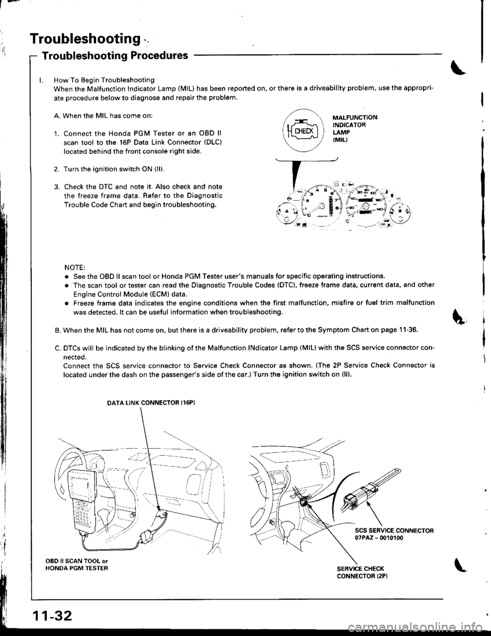
A. When the MIL has come on:
'1. Connect the Honda PGM Tester or an OBD ll
scan tool to the 16P Data Link Connector (DLC)
located behind the front console right side.
2. Turn the ignition switch ON (ll).
3. Check the DTC and note it. Also check and note
the freeze frame data. Refer to the Diagnostic
Trouble Code Chart and begin troubleshooting.
NOTE:
. SeetheOBDll scantool or Honda PGM Tester user's manuals for specific operating instructions.
. The scan tool or tester can read the Diagnostic Trouble Codes (OTC). freeze frame data, current data, and other
Engine Control Module (ECM) data.
. Freeze frame data indicates the engine conditions when the first malfunction, misfire or luel trim malfunction
was detected. lt can be useful information when troubleshooting.
B. When the MIL has not come on, but there is a driveability problem, refer to the Symptom Chart on page 11-36.
C. DTCS wjll be indicated by the blinking of the Malfunction lNdicator Lamp {MlL) with the SCS service connector con-
nected.
Connect the SCS service connector to Service Check Connector as shown. (The 2P Service Check Connector is
located under the dash on the passenger's side of the car,) Turn the ignition switch on (lll.
scs sERvlcE coNNEcToEo?PAZ - 0010100
MAI-FUNCTIONINDICATORLAMP{MIL)
DATA LINK CONNECTOR Il6PI
OBO ll SCAN TOOL orHONDA PGM TESTER
Page 241 of 1681
Troubleshooting
Troubleshooting Procedures (cont'd)
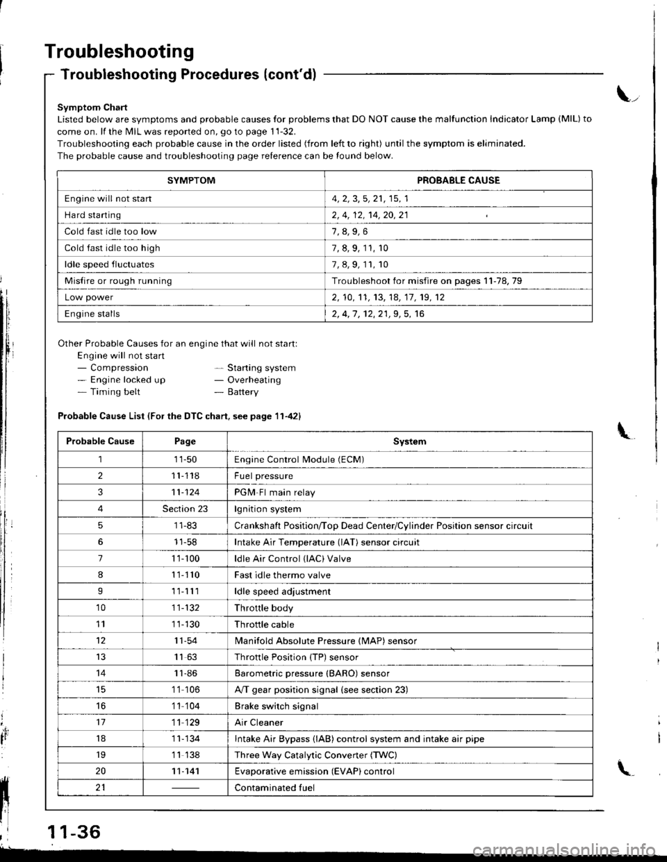
Symptom Chart
Listed below are symptoms and probable causes for problems that DO NOT cause the malfunction Indicator Lamp (MlL) to
come on. lf the MIL was reported on, go to page 11-32.
Troubleshooting each probable cause in the order listed (from left to right) until the symptom is eliminated.
The probable cause and troubleshooting page relerence can be found below.
Other Probable Causes for an engine that will not start:
Engine will not sta rt- Compression- Engine locked up- Timing belt
\_
- Starting system- Overheating- Battery
'4,
It
Probable Cause List (For the DTC chart. see page 11-421
Probable CausePageSystem
111-50Engine Control Module (ECM)
211118Fuel pressure
311-124PGM-Fl main relay
4Section 23lgnition system
51 1-83Crankshaft Position/ToD Dead Center/Cylinder Position sensor circuit
11-58Intake Air Temperature (lAT) sensor circuit
71 '�t- 100ldle Air Control (lAC) Valve
811110Fast idle thermo valve
I11lllldle speed adjustment
'1011-132Throttle body
111 1-130Throttle cable
1211-54lvlanifold Absolute Pressure {MAP) sensor
IJ1163Throttle Position {TP) sensor
1411-86Barometric pressure (BARO) sensor
1 '1 106A/T gear position signal {see section 23)
16'1 1 104Brake switch signal
1711 129Air Cleaner
181 1- 134Intake Air Bypass {lAB} control system and intake air pipe
19'1 1 138Three Way Catalytic Convener (TWC)
2011-141Evaporative emission (EVAP) control
21Contaminated fuelll ll 21 | - | cont"-in"t"o tu"
11 l-
I
,l 11-36
-
SYMPTOMPROBABLE CAUSE
Engine will not stan4, 2, 3,5, 21, 15, 1
Hard starting2, 4, 12, 14,20,21
Cold fast idle too low
Cold fast idle too high7, 8, 9, 11, r0
ldle speed fluctuates7,8,9,11,10
Misfire or rough runningTroubleshoot for misfire on pages 11-78,79
Low power2, 10,'t1, 13, 14, 17, 19, 12
Engine stalls2, 4,1 , 12,21,9, 5, 16
Page 244 of 1681
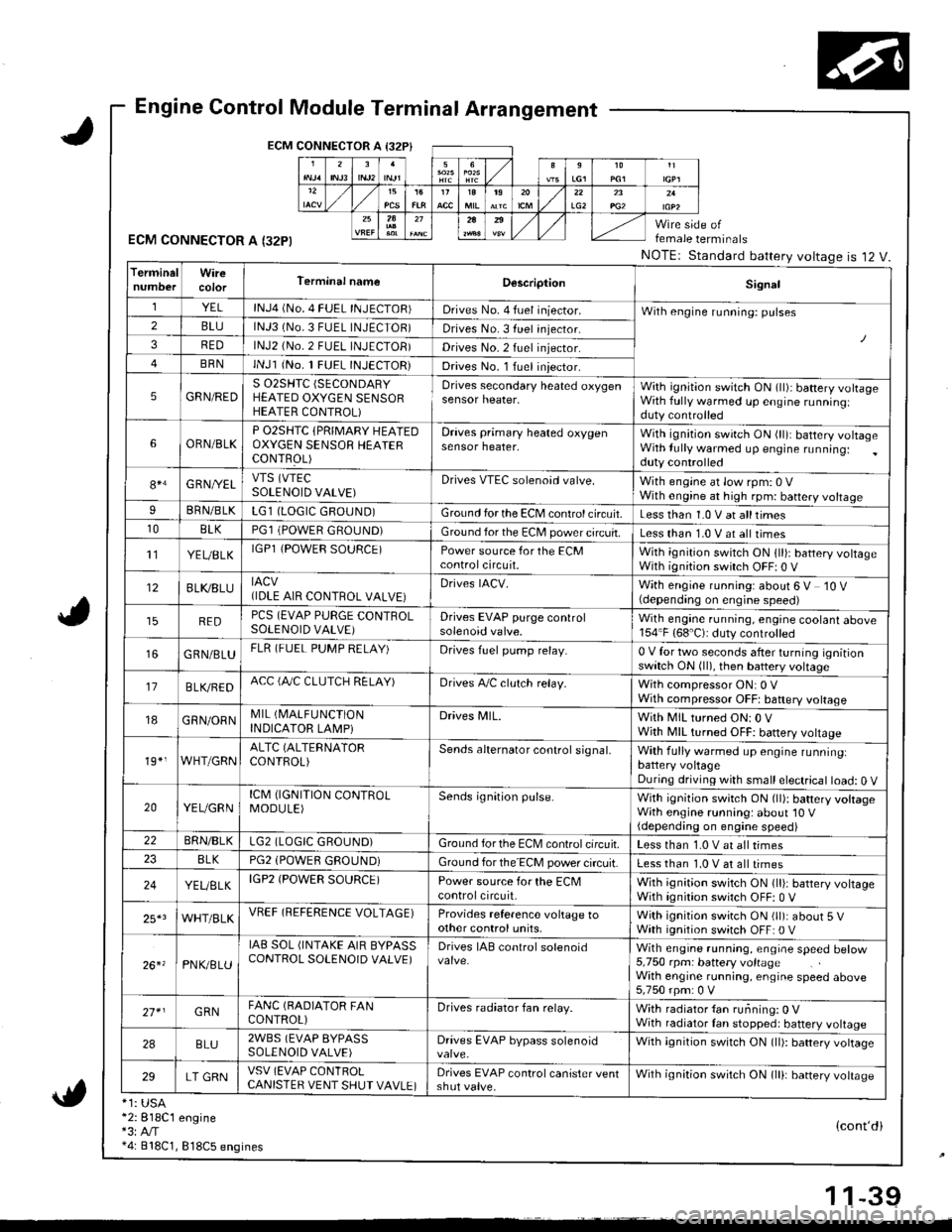
Engine Control Module Terminal Arrangement
ECM CONNECTOR A I32P}
ECM CONNECTOR A I32PI
*1: USA*2:818C1 engine*3:A,/T*4: 818C1, 818C5 engines
female terminals
NOTEr Standard battery voltageis 12 V.
{cont'di
LG22A
TerminalWireTerminal nameDescriptionSignal
YELlNJ4 (No. 4 FUEL INJECTOR)Drives No. 4 fuel iniector.With engine running: pulses2BLUlNJ3 (No.3 FUEL INJECTOR)Drives No. 3 fuel injector.
3REDlNJ2 (No.2 FUEL INJECTOB)Drives No.2 fuel injector.
BRNlNJl (No. 1 FUEL INJECTOR)Drives No. l Iuel iniector.
5GRN/REDS 02SHTC (SECONDARY
HEATED OXYGEN SENSORHEATER CONTROL)
Drives secondary heated oxygensensor heater,With ignition switch ON (ll)i battery volrageWith fully warmed up engine runningiduty controlled
6ORN/BLKP O2SHTC {PRIMARY HEAIEDOXYGEN SENSOB HEAIERCONTFOL)
Draves primary heated oxygensensor heater,With ignition swirch ON (ll): battery voltageWith lully warmed up engine running:duty controlled
84G RNI/ELVTS (VTEC
SOLENOID VALVE)Drives VTEC solenoid valve.With engine at low rpm: 0 VWith engine at high rpm: battery voltageIBRN/BLKLG1 (LOGIC GROUND)Ground for the ECM control circuit.Less than 1.0 V at alltimes10BLKPGl (POWER GROUND)Ground for the EC[, power circuit.Less than 1.0 V at all times't'lYEUBLKIGPl {POWER SOURCE)Power source for the ECMcontrolcircuit.With ignition switch ON 1ll): battery voltageWith ignition switch OFF| 0 V
12BLI(8LUIACV(IDLE AIR CONTROL VALVE}Drives IACV.With engine running: about 6 V 10 V(depending on engine speed)
REDPCS (EVAP PURGE CONTROLSOLENOID VALVE)Drives EVAP purge controlsolenoid valve.Wilh engane running, engine coolant above154"F (68'C): duty controlled
GRN/BLUFLR (FUEL PUMP RELAY)Drives fuel pump relay.0 V for two seconds after turning ignitionswitch ON (ll), then battery voltage
17B LVBEDACC (fuC CLUTCH RELAY)Drives A,/C clulch relay.With compressor ON: 0 VWith compressor OFFt baftery voltage
18GRN/ORNMIL (I\4ALFUNCTION
INDICATOR LAMPiDrives MlL.With MIL turned ON:0 VWjth MIL turned OFF: battery vottage
19*,WHT/GRNALTC (ALTERNATOR
CONTROL)Sends alternator control signal,With fully warmed up engine runninglbattery voltageDuring driving with small electrical load: 0 V
20YEUGRNICM (IGNITION CONTROLMODULE)Sends ignition pulse.With ignition switch ON (ll): battery voltageWith engine running: about'10 V(depending on engine speed)22BRN/BLKLG2 (LOGIC GROUND)Ground forthe ECM controlcifcuit.Less than 1.0 V at all times8LKPG2 (POWEfl GROUND)Ground for the ECM power circuit.Less than 1.0 V at all times
24YEUELKIGP2 (POWER SOURCE)Power source for the ECMcontrolcircuit,With ignition switch ON {lli: battery voltageWith ignition switch OFF: 0 V
25*3WHT/BLKVREF (REFERENCE VOLTAGE)Provides reference voltage toother control units,With ignition swirch ON (ll): about 5 VWath ignition switch OFF: 0 V
26. 'PNK/8LU
IAB SOL (INTAKE AIR BYPASSCONTROL SOLENOID VALVE)Drives IAB conlrol solenoidWith engrne running, engrae speed betow5,750 rpm: battery voltageWith engine running, engine speed above5,750 rpm: 0 V
27* IGRNFANC (BADIATOR FANCONTROL)Drives radiator fan relay.With radiator {an running: 0 VWith radiator Ian stopped: battery voltage
2ABLU2WBS (EVAP BYPASSSOLENOID VALVE)Drives EVAP bypass solenoidWith ignition switch ON (ll): battery vottage
29LT GRNVSV (EVAP CONlROLCANISTER VENT SHUT VAVLE)Drives EVAP control canister ventshut valve.Wilh ignilion switch ON lll): banery votrasc
1 1-39
Page 247 of 1681
1l
Troubleshooting
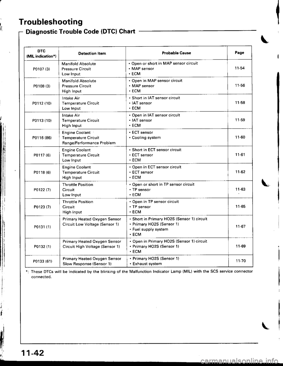
Diagnostic Trouble Gode (DTCI Chart
*: These DTCS will be indicated by the blinking ot the lvalfunction Indicator Lamp (MlL) with the SCS service connector
connected.
Ia
\
\
il
\
DTC
lMlL indication*lDetection ltemProbabls CausePage
P0107 (3)
Manifold Absolute
Pressure Circuit
Low Input
Open or short in MAP sensor circuit
MAP sensor
ECM
'11-54
P0108 (31
Manifold Absolute
Pressure Circuit
High Input
Open in MAP sensor circuit
MAP sensor
ECM
tt-5t,
P0112 (10)
Intake Air
Temperature Circuit
Low Input
Short in IAT sensor circuit
IAT sensor
ECM
11.58
P0113 {10)
lntake Air
Temperature Circuit
High Input
Open in IAT sensor circuit
IAT sensor
ECM
1'�1-59
P0116 (86)
Engine Coolant
Temperature Circuit
Range/Performance Problem
. ECT sensor' Cooling system11-60
P0117 (6)
Engine Coolant
Temperature Circuit
Low Input
Short in ECT sensor circuit
ECT sensor
ECM
1 '�t-61
P0118 {6)
Engine Coolant
Temperature Circuit
High Input
Open in ECT sensor circuit
ECT sensor
ECt\,4
1't -62
P0122l7l
Throttle Position
Circuit
Low Input
Open or shon in TP sensor circuit
TP sensor
ECM
11,63
P0123 (7)
Throttle Position
Circuit
High Input
Open in TP sensor circuit
TP sensor
ECM
I t-oc
P0131 (1 )
Primary Heated Oxygen Sensor
Circuit Low Voltage (Sensor 1)
Shon in Primary HO2S (Sensor'l) circuit
Primary H02S {Sensor 1)
Fuel supply system
ECM
11-67
P0132 (1)Primary Heated Oxygen Sensor
Circuit High Voitage (Sensor 1)
Open in Primary HO2S (Sensor 1) circuit
Primary HO2S (Sensor 1)
ECM
11-69
P0133 (61)Primary Heated Oxygen Sensor
Slow Response (Sensor 1)
. Primary HO2S (Sensor 1). Exhaust system1 1-70
,r:' 11-42
L
Page 254 of 1681
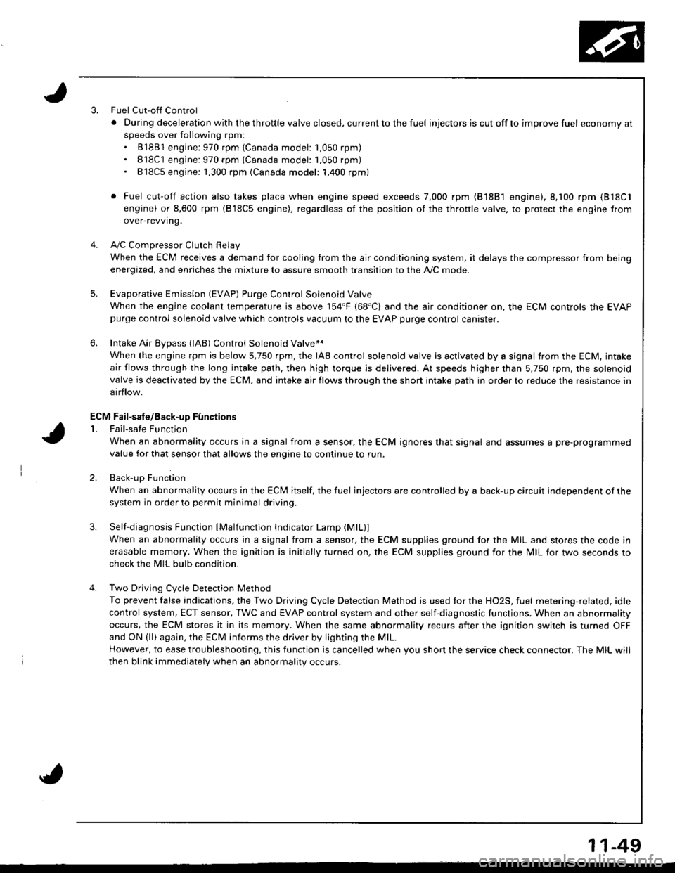
3.Fuel Cut-off Control
. Du ring dece leration with the th rottle va lve closed, cu rrent to the fuel injectors is cutoffto improvefuel economyat
speeds over following rpm:. B'1881 engine: 970 rpm {Canada model: 1.050 rpm). B18C1 engine:970 rpm {Canada model: 1.050 rpm). 818C5 engine: 1,300 rpm (Canada model: 1,400 rpm)
. Fuel cut-off action also takes place when engine speed exceeds 7,000 rpm (B'1881 engine), 8.100 rpm (818C1
engine) or 8,600 rpm (818C5 engine), regardless ol the position of the thronle valve, to protect the engine from
over-revving.
A,,/C ComDressor Clutch Relav
When the ECM receives a demand for cooling from the air conditioning system, it delays the compressor from being
energized, and enriches the mixture to assure smooth transition to the A,/C mode.
Evaporative Emission (EVAP) Purge Control Solenoid Valve
When the engine coolanl temperature is above '154'F (68'C) and the air conditioner on. the ECM controls the EVAPpurge control solenoid valve which controls vacuum to the EVAP purge control canister.
Intake Air Eypass (lAB) Control Solenoid Valve*a
When the engine rpm is below 5,750 rpm, rhe IAB control solenoid valve is activated by a signal from the ECM, intake
air flows through the long intake path, then high torque is delivered. At speeds higher than 5,750 rpm, the solenoidvalve is deactivated by the ECM, and intake air flows through the short intake path in order to reduce the resistance in
airflow.
Sell-diagnosis Function lMalfunction Indicator Lamp {MlL)lWhen an abnormality occurs in a signal from a sensor, the ECM supplies ground for the MIL and stores the code in
erasable memory. When the ignition is initially turned on, the ECM supplies ground for the N4lL tor two seconds to
check the MIL bulb condition.
Two Driving Cycle Detection Method
To prevent false indications, the Two Driving Cycle Detection Method is used for the HO2S, fuel metering-related, idle
control system, ECT sensor, TWC and EVAP control system and other self-diagnostic functions, When an abnormality
occurs, the ECM stores it in its memory. When the same abnormality recurs after the ignition switch is turned OFFand ON (ll)again, the ECM informs the driver by lighting the MlL.
However, to ease troubleshooting, this function is cancelled when you shon the service check connector. The MIL will
then blink immediately when an abnormality occurs.
4.
5.
6.
3.
4.
ECM Fail-safe/8ack.up F0nctions
1. Fail-sate Function
When an abnormality occurs in a signal from a sensor, the ECM ignores that signal and assumes a pre-programmed
value for that sensor that allows the enqine to continue to run.
2. Back-uo Function
When an abnormality occurs in the ECM itself, the fuel injectors are controlled by a back-up circuit independent of the
system in order to permit minimal driving.
11-49
Page 255 of 1681
I
I
It:
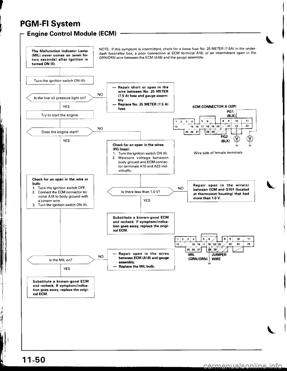
PGM-FI System
Engine Control Module {ECMI
,i
I
{
ili
NOTE: lf this svmotom is intermittent, check for a loose fuse No. 25 METER (7.5A) in the under_
dash fuse/relay box, a ooor connection at ECM terminal A18, or an intermittent open in the
GRN/ORN wire between the ECM (A18) and the gauge assembly.
Wire side of female terminals
I
The Mellunction Indicator Lamp(MlLl never com€3 on leven foltwo secondsl alter ignition islurn6d ON lll).
Turn the ignition switch ON (lli.
- Repair short or open in th€wire betwe€n No. 25 METER{7.5 A}fuse and gauge assem-bty.- ReDlaco No.25 METER 17.5 A)fuse.
ls the low oil pressure light on?
Try to start the engine,
Check for an open in ih6 wires
IPG lines):1. Turnthe ignition switch ON (ll).
2. Measure voltage betweenbody ground and ECM connec-tor terminals A10 and A23 indi-vidually.
Chock for an open in the wire orbulb:1. Turn the ignition sw;tch OFF.2. Connectthe ECM connector terminal 418 to body ground with
3. Turn the ignition switch ON (ll).
Repair open in the wire(slbetween ECM and G101 (located
at thermostat housingl that hadmore than 1.0 V.
ls there less than 1.0 V?
Substitute . known-good ECMand .echeck, lf symptom/indica-tion goes away, replace the origi-nalECM.
- R€pair open in the wiresb€tweon ECM {A18land gaug€
ess€mbly.- Replace the MIL bulb.
ls the MIL on?
Substitute a known-9ood ECMand rech6ck. It symptom/indica-tion goes away, repbce the origi-nal ECM.
ECM CONNECTOR A {32P)
15 16 17 18 19
r 2 3 al 15 Ga910 11
12 ,, t5 16 1tt920/22 23 2a
25 26 211184tt-MILJUMPER(GRN/ORN) I WIRE
Page 311 of 1681
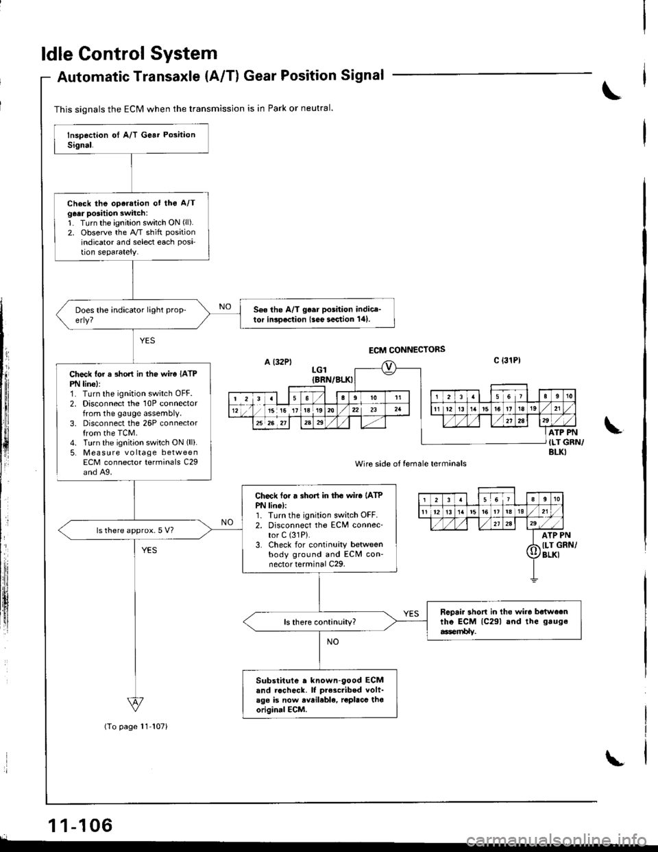
ldle Control System
Check lor a 3hon in the wiro IATPPN linel:1. Turn the ignition switch OFF.2. Disconnect the 10P connectorfrom the gauge assembly.3. Disconnect the 26P connectorfrom the TCM.4. Turn the ignition switch ON (ll).
5. Mea su re voltage betweenECM connector terminals C29and A9.
Automatic Transaxle {A/T) Gear Position Signal
1 1-106r.
This signals the ECM when the transmission is in Park or neutral.
(To page 11-107)
Check the oparation ot the A/Tg6ar posilion switch:1. Turn the ignition switch ON (ll).
2. observe the A/T shitt position
indicator and select each Posi'tion separately.
560 the A/T go.r position indice-tor inroection lseo section 141.
Check tor r 3hort in tho wiro (ATP
PN lino):1. Iurn the ignition switch OFF.2. Disconnect the ECM connec-tor C (31P).
3. Check for continuity betweenbody ground and ECM con'nector terminal C29.
ls there approx.5 V?
Rcpair short in the wir6 batwoentho ECM lc29l and the gauge
6er$lv.
Substitute a known-90od ECMand rccheck. lf prescribed volt-ago is now avail.ble, rcplacc thooriginal ECM.
,PN
GRN/
LGIIBRN/BLKI
ATP PN
ILT GRN/BLKI
Wire side of temale terminals
12355It0
11 1213t319
2A29/,a
I ArP
d llr (
Il/BLKI
Page 366 of 1681
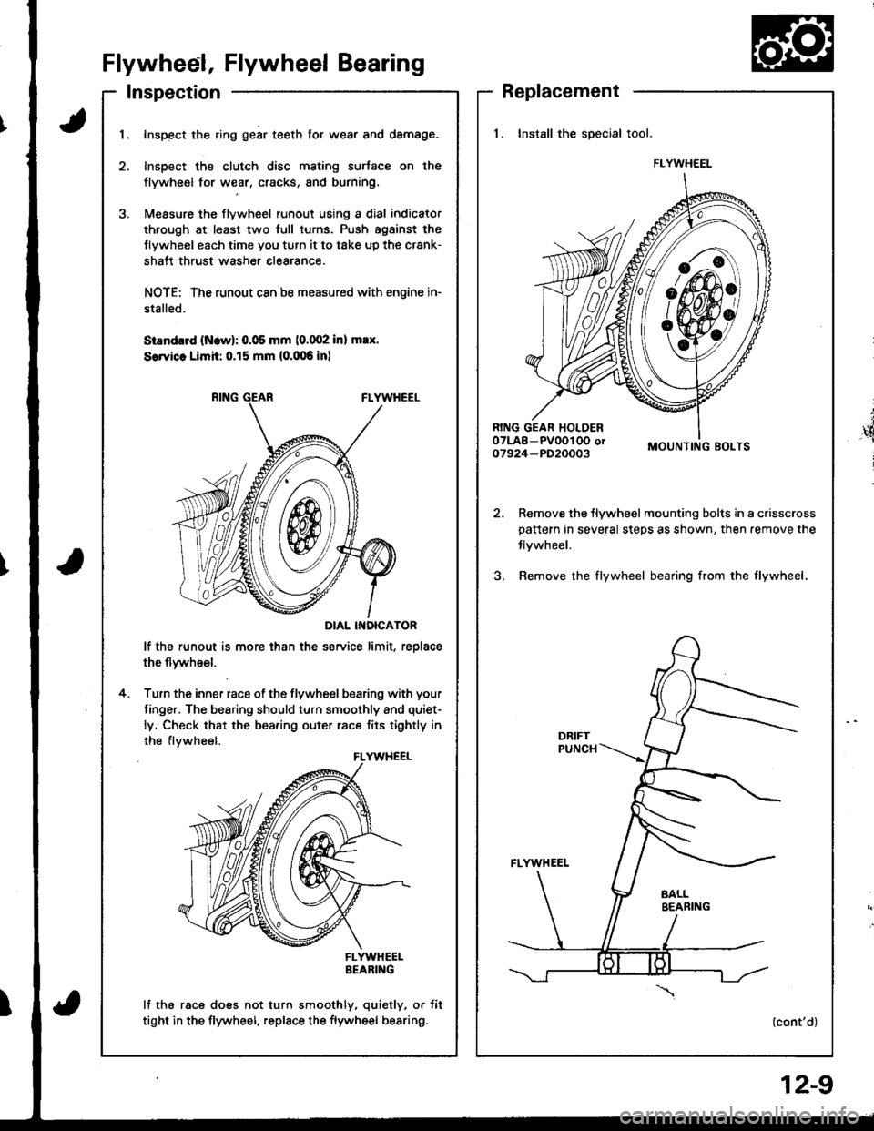
Flywheel, Flywheel Bearing
Inspection
t
',4
i
Replacement
1. Install the special tool.
MOUNTING BOLTS
Remove the flywheel mounting bolts in a crisscrosspattern in several steps as shown, then.emove the
Jlvwheel.
Bemove the flywheel bearing from the flywheel.
(cont'd)
FLYWHEEL
I
1.Inspect the ring gear teeth tor wear and damage.
Inspect the clutch disc mating surtace on the
flywheel for wear, cracks, and burning.
l\,reasure the flywheel runout using a dial indicator
through at least two full turns. Push agsinst the
Jlywheel each time you turn it to take up the crank-
shatt thrust washer clearance.
NOTE: The runout can ba measured with engine in-
stalled.
SiEndrrd (Ncw): 0.05 mm (0.002 inl max.
SerYicc Llmh: 0.15 mm (0.006 inl
DIAL INOICATOR
lf the runout is more than the service limit, reolace
the flywheel.
Turn the inner race of the flywheel bearing with your
tinger. The bearing should turn smoothly and quiet-
ly. Check that the bearing outer race tits tightly in
the flvwheel.
FLYWHEELBEARING
lf the race does not turn smoothly, quietly, or tit
tight in the flywheel, replace the flywheel bearing.
4.
FLYWHEEL
12-9