Ventilation Hyundai Ioniq Electric 2017 Owner's Manual
[x] Cancel search | Manufacturer: HYUNDAI, Model Year: 2017, Model line: Ioniq Electric, Model: Hyundai Ioniq Electric 2017Pages: 582, PDF Size: 37.73 MB
Page 99 of 582
Safety system of your vehicle
2
Important safety precautions .............................2-2Always wear your seat belt ..........................................2-2
Restrain all children .........................................................2-2
Air bag hazards ................................................................2-2
Driver distraction .............................................................2-2
Control your speed ..........................................................2-3
Keep your vehicle in safe condition ............................2-3
Seats ........................................................................2-4 Safety precautions ..........................................................2-6
Front seats ..........................................................................2-7
Rear seats .........................................................................2-13
Headrest ...........................................................................2-16
Seat warmers and air ventilation seats.....................2-21
Seat belts .............................................................2-25 Seat belt safety precautions ......................................2-25
Seat belt warning light .................................................2-26
Seat belt restraint system ...........................................2-29
Additional seat belt safety precautions ...................2-34
Care of seat belts ..........................................................2-36 Child restraint system (CRS) .............................2-37
Our recommendation:Children always in the rear ..2-37
Selecting a Child Restraint System (CRS) ................2-38
Installing a Child Restraint System (CRS)..................2-40
Air bag - supplemental restraint system ........2-50 Where are the air bags? ..............................................2-53
How does the air bags system operate? .................2-58
What to expect after an air bag inflates ................2-62
Why didn't my air bag go off in a collision? ...........2-64
SRS care ...........................................................................2-69
Additional safety precautions .....................................2-70
Air bag warning labels ..................................................2-71
This chapter provides you with important information about how to protect yourself and your passengers.
It explains how to properly use your seats and seat belts, and how your air bags work.
Additionally, this chapter explains how to properly restrain infants and children in your vehicle.
Page 102 of 582
2-4
SSEE AA TTSS
Safety system of your vehicle
OAEE036001
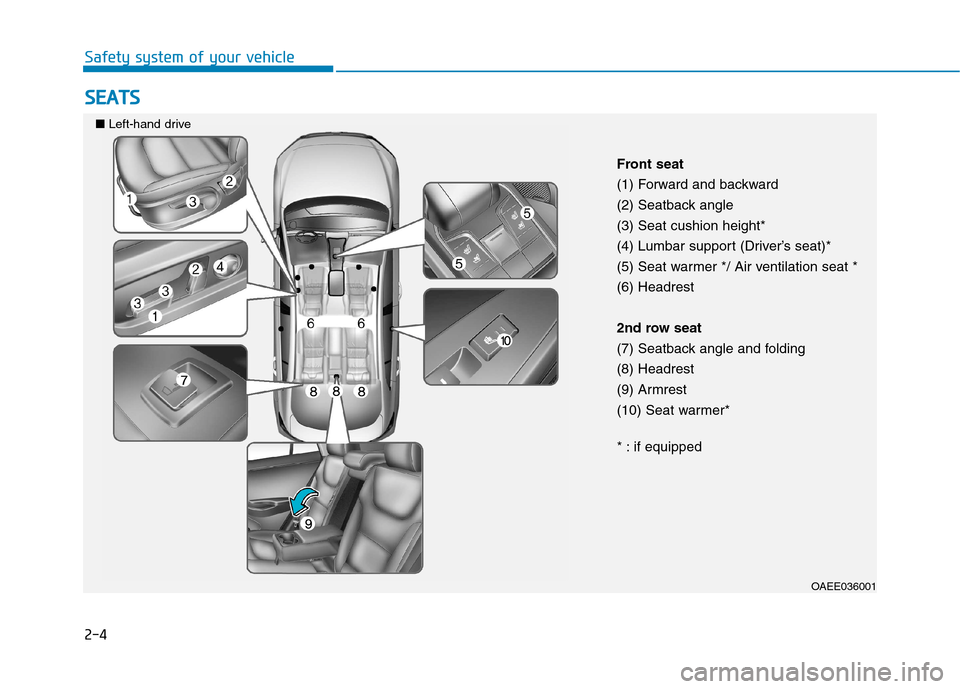
Front seat
(1) Forward and backward
(2) Seatback angle(3) Seat cushion height*
(4) Lumbar support (Driver’s seat)*
(5) Seat warmer */ Air ventilation seat *(6) Headrest
2nd row seat
(7) Seatback angle and folding(8) Headrest
(9) Armrest
(10) Seat warmer*
* : if equipped
■
Left-hand drive
Page 103 of 582
2-5
Safety system of your vehicle
2
OAEE036001R
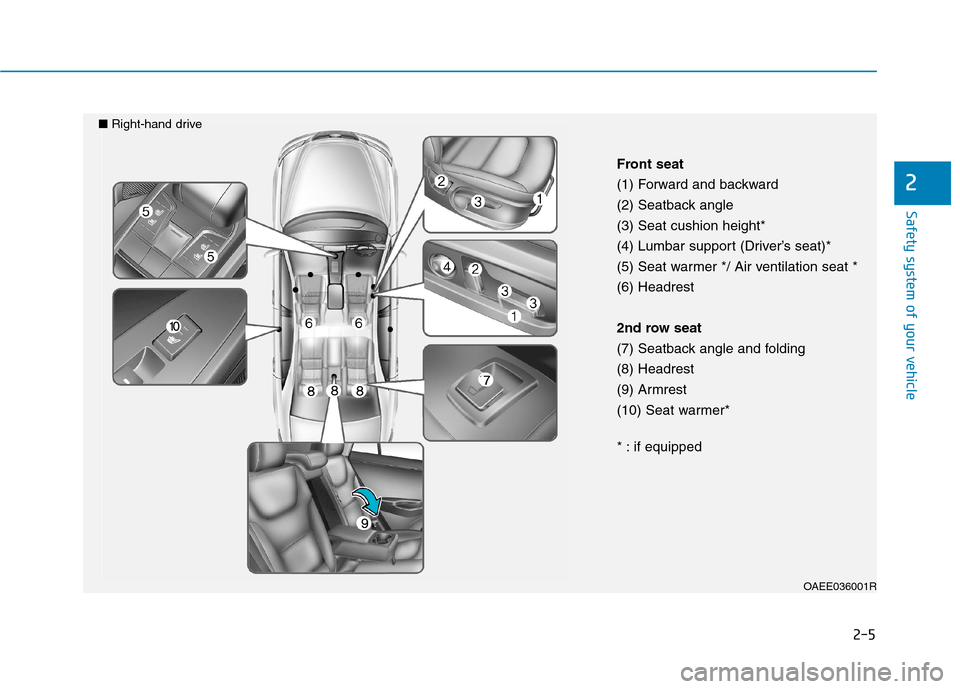
Front seat
(1) Forward and backward
(2) Seatback angle(3) Seat cushion height*
(4) Lumbar support (Driver’s seat)*
(5) Seat warmer */ Air ventilation seat *(6) Headrest
2nd row seat
(7) Seatback angle and folding(8) Headrest
(9) Armrest
(10) Seat warmer*
* : if equipped
■
Right-hand drive
Page 120 of 582
2-22
Safety system of your vehicle
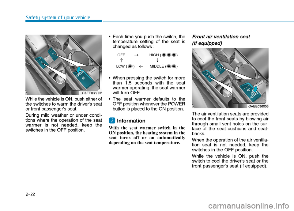
While the vehicle is ON, push either of
the switches to warm the driver's seator front passenger's seat.
During mild weather or under condi-
tions where the operation of the seat
warmer is not needed, keep the
switches in the OFF position. Each time you push the switch, the
temperature setting of the seat is
changed as follows :
When pressing the switch for more than 1.5 seconds with the seat
warmer operating, the seat warmer
will turn OFF.
The seat warmer defaults to the OFF position whenever the POWER
button is placed to the ON position.
Information
With the seat warmer switch in the
ON position, the heating system in the
seat turns off or on automatically
depending on the seat temperature.
Front air ventilation seat (if equipped)
The air ventilation seats are provided
to cool the front seats by blowing air
through small vent holes on the sur-
face of the seat cushions and seat-
backs.
When the operation of the air ventila-
tion seat is not needed, keep the
switches in the OFF position.
While the vehicle is ON, push the
switch to cool the driver's seat or thefront passenger's seat (if equipped).
i
OAEE036002
OAEE036003
OFF HIGH ( )
LOW ( ) MIDDLE ( )
��
�
�
Page 121 of 582
2-23
Safety system of your vehicle
2
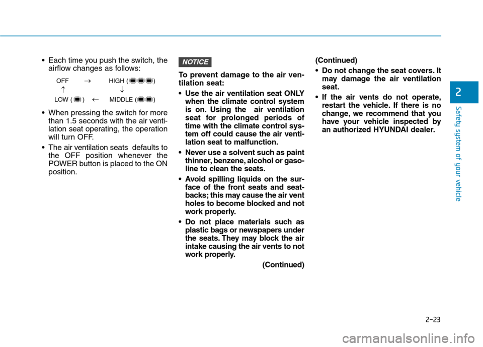
Each time you push the switch, theairflow changes as follows:
When pressing the switch for more than 1.5 seconds with the air v enti-
lation seat operating, the operation
will turn OFF.
The air v entilation seats def aults to
the OFF position whenever the
POWER button is placed to the ONposition. To prevent damage to the air ven-tilation seat:
Use the air ventilation seat ONLY
when the climate control system
is on. Using the air ventilation
seat for prolonged periods of
time with the climate control sys-tem off could cause the air venti-lation seat to malfunction.
Never use a solvent such as paint thinner, benzene, alcohol or gaso-
line to clean the seats.
Avoid spilling liquids on the sur- face of the front seats and seat-
backs; this may cause the air vent
holes to become blocked and not
work properly.
Do not place materials such as plastic bags or newspapers under
the seats. They may block the airintake causing the air vents to not
work properly.
(Continued)(Continued)
Do not change the seat covers. It
may damage the air ventilation seat.
If the air vents do not operate, restart the vehicle. If there is no
change, we recommend that you
have your vehicle inspected by
an authorized HYUNDAI dealer.NOTICE
OFF HIGH ( )
LOW ( ) MIDDLE ( )
��
�
�
Page 271 of 582
3-102
Convenient features of your vehicle
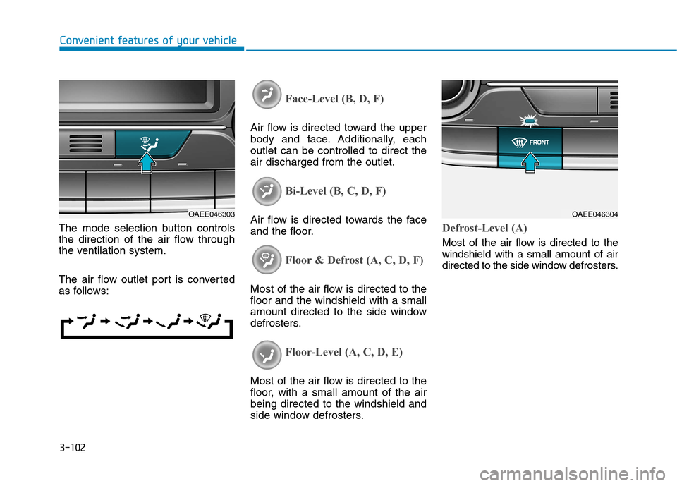
The mode selection button controls
the direction of the air flow through
the ventilation system.
The air flow outlet port is converted
as follows:
Face-Level (B, D, F)
Air flow is directed toward the upper
body and face. Additionally, eachoutlet can be controlled to direct theair discharged from the outlet.
Bi-Level (B, C, D, F)
Air flow is directed towards the face
and the floor.
Floor & Defrost (A, C, D, F)
Most of the air flow is directed to the floor and the windshield with a small
amount directed to the side window
defrosters.
Floor-Level (A, C, D, E)
Most of the air flow is directed to the
floor, with a small amount of the airbeing directed to the windshield and
side window defrosters.
Defrost-Level (A)
Most of the air flow is directed to the windshield with a small amount of air
directed to the side window defrosters.
OAEE046303OAEE046304
Page 277 of 582
3-108
Convenient features of your vehicle
System operation
Ventilation
1. Set the mode to the position.
2. Set the air intake control to theoutside (fresh) air position.
3. Set the temperature control to the desired position.
4. Set the fan speed control to the desired speed.
Heating
1. Set the mode to the position.
2. Set the air intake control to theoutside (fresh) air position.
3. Set the temperature control to the desired position.
4. Set the fan speed control to the desired speed.
5. If dehumidified heating is desired, turn the air conditioning system on.
If the windshield fogs up, set the mode to the or position.
Operation Tips
To keep dust or unpleasant fumesfrom entering the vehicle through
the ventilation system, temporarily
set the air intake control to the
recirculated air position. Be sure to
return the control to the fresh air
position when the irritation has
passed to keep fresh air in the
vehicle. This will help keep the driv-
er alert and comfortable.
Air for the heating/cooling system is drawn in through the grilles just
ahead of the windshield. Care
should be taken that these are not
blocked by leaves, snow, ice or
other obstructions.
To prevent interior fog on the wind- shield, set the air intake control to
the fresh air position and fan speed
to the desired position, turn on theair conditioning system, and adjust
the temperature control to desired
temperature.
Air conditioning
HYUNDAI Air Conditioning Systemsare filled with R-134a or R1234yf
refrigerant.
1. Start the vehicle. Push the air con- ditioning button.
2. Set the mode to the position.
3. Set the air intake control to the out- side air or recirculated air position.
4. Adjust the fan speed control and temperature control to maintain
maximum comfort.
Information
Your vehicle is filled with R-134a or
R-1234yf according to the regulation
in your country at the time of produc-
tion. You can find out which air condi-
tioning refrigerant is applied to your
vehicle on the label located inside of
the hood.
i
Page 495 of 582
7-29
7
Maintenance
Battery recharging
By battery charger
Your vehicle has a maintenance-free,
calcium-based battery.
If the battery becomes dischargedin a short time (because, for exam-
ple, the headlights or interior lights
were left on while the vehicle was
not in use), recharge it by slow
charging (trickle) for 10 hours.
If the battery gradually discharges because of high electric load while
the vehicle is being used, recharge
it at 20-30A for two hours. Always follow these instructions
when recharging your vehicle’s
battery to avoid the risk of SERI-
OUS INJURY or DEATH from
explosions or acid burns:
Before performing mainte-
nance or recharging the bat-
tery, turn off all accessories
and place the POWER buttonto the OFF position.
Keep all flames, sparks, or
smoking materials away from
the battery.
Always work outdoors or in an area with plenty of ventilation.
Wear eye protection when
checking the battery during
charging.
The battery must be removed
from the vehicle and placed ina well ventilated area.
(Continued)
WARNING (Continued)
Watch the battery during
charging, and stop or reduce
the charging rate if the battery
cells begin boiling violently.
The negative battery cable
must be removed first and
installed last when the battery
is disconnected. Disconnect
the battery charger in the fol-
lowing order:
(1) Turn off the battery chargermain switch.
(2) Unhook the negative
clamp from the negative
battery terminal.
(3) Unhook the positive clamp from the positive batteryterminal.
Always use a genuine HYUNDAI
approved battery when you
replace the battery.
Page 513 of 582

7-47
7
Maintenance
Instrument panel fuse panel
Fuse NameSymbolFuse RatingCircuit Protected
Module 5MODULE510A
Electro Chromic Mirror, A/V & Navigation Head Unit, Audio, Driver IMS Module,
Rear Seat Warmer Module, Auto Head Lamp Leveling Device Module,
Head Lamp Leveling Device Actuator LH/RH, Vess Unit,
Front Air Ventilation Seat Control Module, Front Seat Warmer Control Module
Module 4MODULE410ALane Keeping Assist Unit, Crash Pad Switch, AEB Unit,
Blind Spot Detection Radar LH/RH, Electronic Parking Brake Switch
Interior Lamp10AFront Vanity Lamp LH/RH, Room Lamp, Overhead Console Lamp,
Luggage Lamp, Wireless Charger Unit, Rain Sensor
Air bag15ASRS Control Module
E- Shifter 1 10ASBW Switch, Front Console Switch
Ignition 1IG125APCB Block
ClusterCLUSTER10AInstrument Cluster
Ignition 3 2 10AIPS Control Module, Main Battery Charging Switch, Charge Lamp, PTC Heater,
A/V & Navigation Head Unit, Instrument Cluster, A/C Control Module
Memory 2MEMORY
27.5AActive Air Flap LH/RH
Module 8MODULE 810AActive Air Flap LH/RH, Electric Water Pump (Engine), VPD Sensor, BMS Control Module,
E/R Junction Block
Air bag IndicatorIND7.5AInstrument Cluster
Start7.5AEPCU, Smart Key Control Module
Page 514 of 582
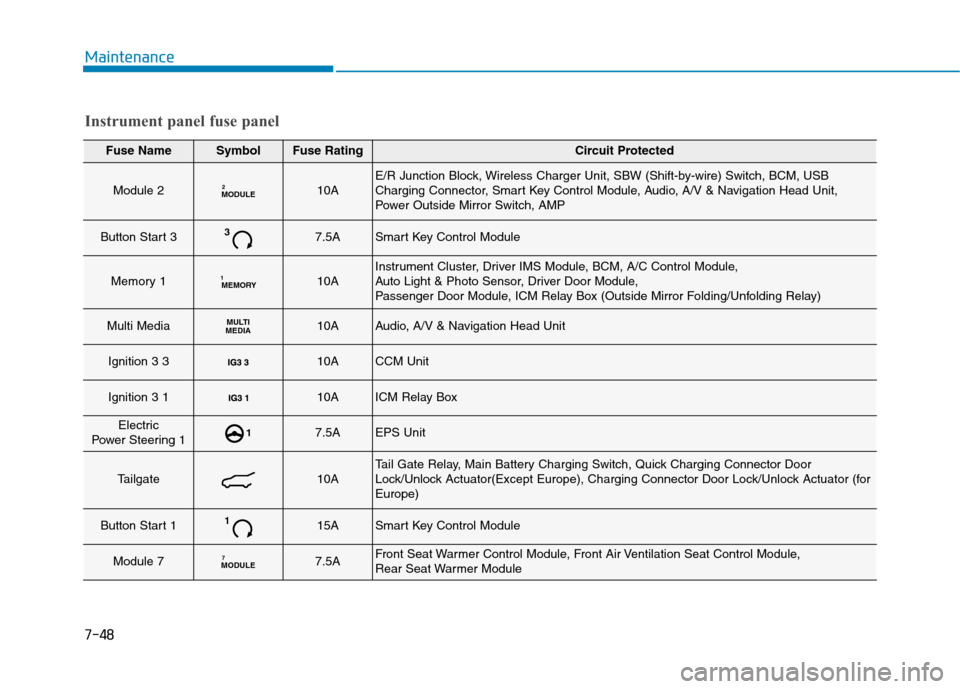
Maintenance
Fuse NameSymbolFuse RatingCircuit Protected
Module 2MODULE210AE/R Junction Block, Wireless Charger Unit, SBW (Shift-by-wire) Switch, BCM, USB
Charging Connector, Smart Key Control Module, Audio, A/V & Navigation Head Unit,
Power Outside Mirror Switch, AMP
Button Start 337.5ASmart Key Control Module
Memory 1MEMORY
110AInstrument Cluster, Driver IMS Module, BCM, A/C Control Module,
Auto Light & Photo Sensor, Driver Door Module,
Passenger Door Module, ICM Relay Box (Outside Mirror Folding/Unfolding Relay)
Multi MediaMULTI
MEDIA10AAudio, A/V & Navigation Head Unit
Ignition 3 3 10ACCM Unit
Ignition 3 1 10AICM Relay Box
Electric
Power Steering 117.5AEPS Unit
Tailgate10ATail Gate Relay, Main Battery Charging Switch, Quick Charging Connector Door
Lock/Unlock Actuator(Except Europe), Charging Connector Door Lock/Unlock Actuator (forEurope)
Button Start 1115ASmart Key Control Module
Module 7MODULE 77.5AFront Seat Warmer Control Module, Front Air Ventilation Seat Control Module,
Rear Seat Warmer Module
Instrument panel fuse panel
7-48