Hyundai Terracan 2003 Owner's Manual
Manufacturer: HYUNDAI, Model Year: 2003, Model line: Terracan, Model: Hyundai Terracan 2003Pages: 349, PDF Size: 4.56 MB
Page 331 of 349
OWNER MAINTENANCE 6-19
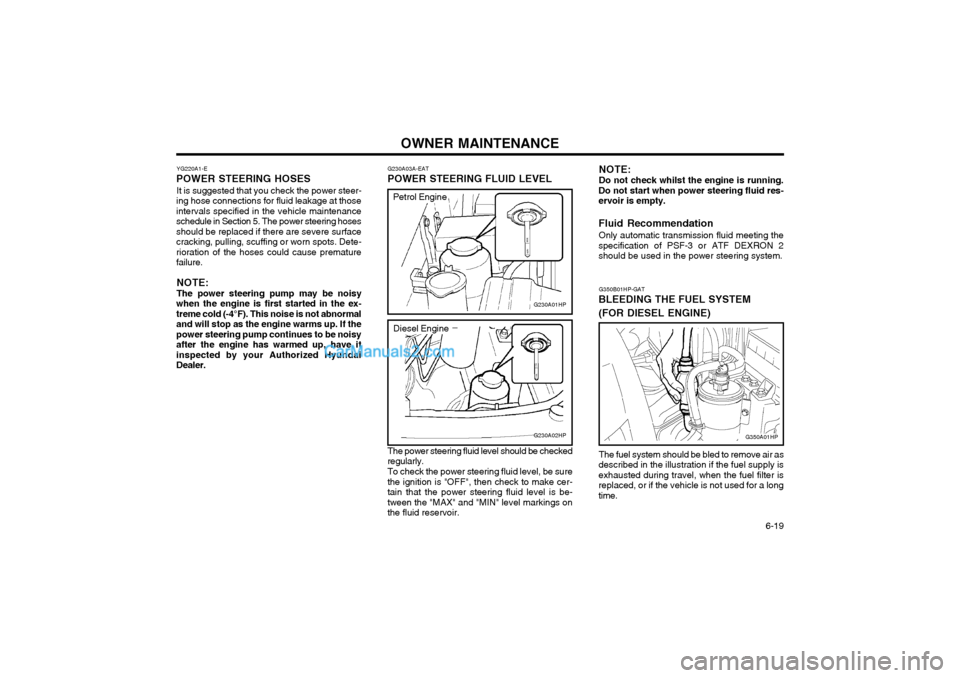
The power steering fluid level should be checked
regularly.
To check the power steering fluid level, be sure
the ignition is "OFF", then check to make cer- tain that the power steering fluid level is be-tween the "MAX" and "MIN" level markings onthe fluid reservoir.
YG220A1-E
POWER STEERING HOSES
It is suggested that you check the power steer-
ing hose connections for fluid leakage at thoseintervals specified in the vehicle maintenanceschedule in Section 5. The power steering hosesshould be replaced if there are severe surfacecracking, pulling, scuffing or worn spots. Dete-rioration of the hoses could cause prematurefailure.
NOTE: The power steering pump may be noisy
when the engine is first started in the ex- treme cold (-4°F). This noise is not abnormaland will stop as the engine warms up. If thepower steering pump continues to be noisyafter the engine has warmed up, have itinspected by your Authorized HyundaiDealer. G230A03A-EAT POWER STEERING FLUID LEVEL
G230A01HP
G230A02HP
Petrol Engine
Diesel Engine
G350B01HP-GAT
BLEEDING THE FUEL SYSTEM (FOR DIESEL ENGINE)
The fuel system should be bled to remove air as
described in the illustration if the fuel supply is exhausted during travel, when the fuel filter isreplaced, or if the vehicle is not used for a longtime.
G350A01HP
NOTE: Do not check whilst the engine is running.
Do not start when power steering fluid res- ervoir is empty. Fluid Recommendation
Only automatic transmission fluid meeting the
specification of PSF-3 or ATF DEXRON 2 should be used in the power steering system.
Page 332 of 349
OWNER MAINTENANCE
6-20
G260A01HP-DAT
REPLACING HEADLIGHT BULBS
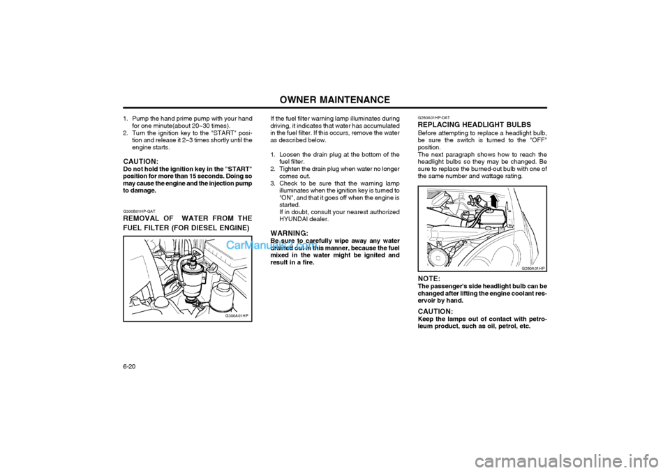
Before attempting to replace a headlight bulb, be sure the switch is turned to the "OFF"position. The next paragraph shows how to reach the headlight bulbs so they may be changed. Besure to replace the burned-out bulb with one ofthe same number and wattage rating. NOTE: The passenger's side headlight bulb can be changed after lifting the engine coolant res-ervoir by hand. CAUTION: Keep the lamps out of contact with petro- leum product, such as oil, petrol, etc.
G260A01HP
G300B01HP-GAT
REMOVAL OF WATER FROM THE FUEL FILTER (FOR DIESEL ENGINE)
G300A01HP If the fuel filter warning lamp illuminates during
driving, it indicates that water has accumulated in the fuel filter. If this occurs, remove the wateras described below.
1. Loosen the drain plug at the bottom of the fuel filter.
2. Tighten the drain plug when water no longer comes out.
3. Check to be sure that the warning lamp illuminates when the ignition key is turned to "ON", and that it goes off when the engine isstarted.If in doubt, consult your nearest authorizedHYUNDAI dealer.
WARNING: Be sure to carefully wipe away any water
drained out in this manner, because the fuel mixed in the water might be ignited andresult in a fire.
1. Pump the hand prime pump with your hand
for one minute(about 20~30 times).
2. Turn the ignition key to the "START" posi- tion and release it 2~3 times shortly until theengine starts.
CAUTION: Do not hold the ignition key in the "START"
position for more than 15 seconds. Doing so may cause the engine and the injection pumpto damage.
Page 333 of 349
OWNER MAINTENANCE 6-21
G270A02HP
WARNING: The halogen bulb contains gas under pres- sure and if impacted could shatter, resultingin flying fragments. Always wear eye pro-tection when servicing the bulb. Protect thebulb against abrasions or scratches andagainst liquids when lighted. Turn the bulbon only when installing in a headlight. Re-place the headlight if damaged or cracked.Keep the bulb out of the reach of childrenand dispose of the used bulb with care.
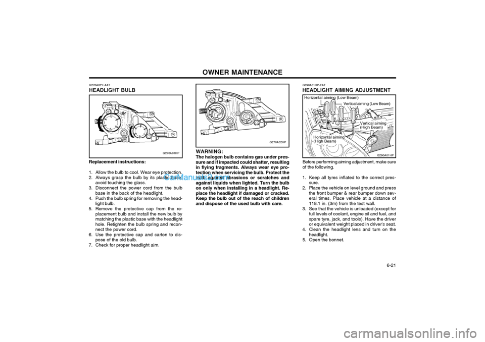
Replacement instructions:
1. Allow the bulb to cool. Wear eye protection.
2. Always grasp the bulb by its plastic base, avoid touching the glass.
3. Disconnect the power cord from the bulb base in the back of the headlight.
4. Push the bulb spring for removing the head- light bulb.
5. Remove the protective cap from the re- placement bulb and install the new bulb by matching the plastic base with the headlighthole. Retighten the bulb spring and recon-nect the power cord.
6. Use the protective cap and carton to dis- pose of the old bulb.
7. Check for proper headlight aim. G270A02Y-AAT
HEADLIGHT BULB
G270A01HP
G290A01HP-EAT
HEADLIGHT AIMING ADJUSTMENT
G290A01HP
Horizontal aiming (Low Beam)
Vertical aiming (Low Beam)
Before performing aiming adjustment, make sure of the following.
1. Keep all tyres inflated to the correct pres- sure.
2. Place the vehicle on level ground and press the front bumper & rear bumper down sev-eral times. Place vehicle at a distance of118.1 in. (3m) from the test wall.
3. See that the vehicle is unloaded (except for full levels of coolant, engine oil and fuel, andspare tyre, jack, and tools). Have the driveror equivalent weight placed in driver's seat.
4. Clean the headlight lens and turn on the headlight.
5. Open the bonnet. Vertical aiming (High Beam)
Horizontal aiming(High Beam)
Page 334 of 349
OWNER MAINTENANCE
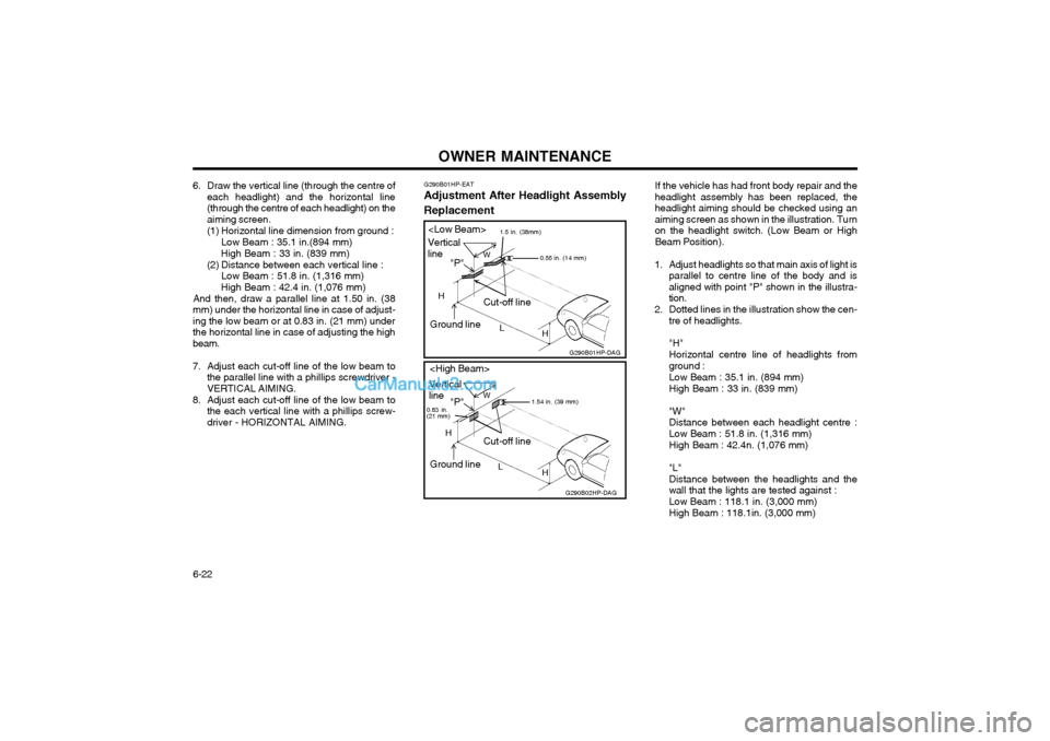
6-22 If the vehicle has had front body repair and the headlight assembly has been replaced, theheadlight aiming should be checked using anaiming screen as shown in the illustration. Turnon the headlight switch. (Low Beam or HighBeam Position).
1. Adjust headlights so that main axis of light is parallel to centre line of the body and isaligned with point "P" shown in the illustra-tion.
2. Dotted lines in the illustration show the cen- tre of headlights. "H" Horizontal centre line of headlights from ground : Low Beam : 35.1 in. (894 mm)High Beam : 33 in. (839 mm) "W" Distance between each headlight centre :Low Beam : 51.8 in. (1,316 mm) High Beam : 42.4n. (1,076 mm) "L" Distance between the headlights and the wall that the lights are tested against : Low Beam : 118.1 in. (3,000 mm) High Beam : 118.1in. (3,000 mm)
G290B01HP-EAT
Adjustment After Headlight Assembly Replacement
6. Draw the vertical line (through the centre of
each headlight) and the horizontal line (through the centre of each headlight) on theaiming screen.
(1) Horizontal line dimension from ground :
Low Beam : 35.1 in.(894 mm)
High Beam : 33 in. (839 mm)
(2) Distance between each vertical line : Low Beam : 51.8 in. (1,316 mm)
High Beam : 42.4 in. (1,076 mm)
And then, draw a parallel line at 1.50 in. (38
mm) under the horizontal line in case of adjust- ing the low beam or at 0.83 in. (21 mm) underthe horizontal line in case of adjusting the highbeam.
7. Adjust each cut-off line of the low beam to the parallel line with a phillips screwdriver - VERTICAL AIMING.
8. Adjust each cut-off line of the low beam to the each vertical line with a phillips screw-driver - HORIZONTAL AIMING.
G290B02HP-DAGG290B01HP-DAG
Cut-off line
L
W
H H
"P"
1.5 in. (38mm)Vertical line
0.55 in. (14 mm)
Cut-off line
L
W
H
H
"P"
Vertical line
1.54 in. (39 mm)
0.83 in. (21 mm)
Ground line
Ground line
Page 335 of 349
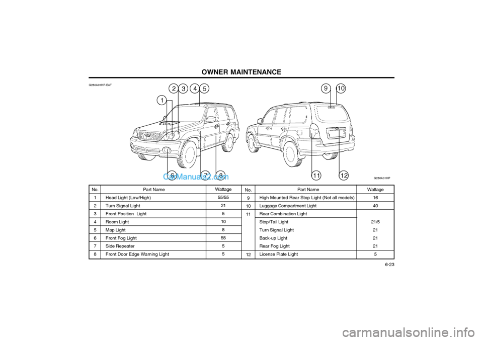
OWNER MAINTENANCE 6-23
No.
9
10 11 12 Wattage
16 40
21/5 2121 21
5
G280A01HP-EAT
No.
1 2 3 4 5 6 7 8 Part Name
Head Light (Low/High)Turn Signal Light
Front Position Light Room Light Map Light Front Fog Light Side Repeater Front Door Edge Warning Light Part Name
High Mounted Rear Stop Light (Not all models)Luggage Compartment Light Rear Combination Light Stop/Tail Light Turn Signal Light Back-up Light Rear Fog Light License Plate LightWattage
55/55 21
5
10
8
55
5 5
G280A01HP
532
87611
910
1
4
12
Page 336 of 349
EMISSION CONTROL SYSTEMS 7-1
vehicle may be damaged. You should inspect the exhaust system each time the car is raisedfor lubrication or oil change. To check condition
1. Holes and gas leaks due to corrosion, dam-
age, etc., should be rectified.
2. The joints should be checked for loose con- nections and gas leakage.
3. The hanger rubber and brackets should be checked for damage. DH010B1-E
1. CRANKCASE EMISSION CONTROL
SYSTEM ; For a Petrol Engine
The positive crankcase ventilation system is
employed to prevent air pollution caused by blow-by gases being emitted from the crank-case.
This system supplies fresh air to the crankcase
through the air cleaner. Inside the crankcase,the fresh air mixes with blow-by gases, thenpasses through the PCV valve into the intakesystem.
ZH010C1-E
2. EVAPORATIVE EMISSION CON-
TROL SYSTEM ; For a Petrol Engine
The Evaporative Emission Control System is designed to prevent fuel vapors from escapinginto the atmosphere.
Canister While the engine is inoperative, fuel vaporsgenerated inside the fuel tank are absorbed andstored in the canister. When the engine isrunning, the fuel vapors absorbed in the canis-ter are drawn into the induction system throughthe purge control solenoid valve.
YH000A1-A
7. EMISSION CON-
TROL SYSTEMS
YH020A1-E
EXHAUST GAS WARNING
Exhaust gases contain carbon monoxide, a
potentially toxic gas that is colorless and odor-less. Avoid breathing exhaust gases.
o Do not run the engine in confined areas, such as garages, any longer than neces- sary to move the car in or out.
o Do not drive with the trunk open. An open trunk may draw exhaust gases into the pas-senger compartment. If you must drive withthe trunk open, drive only with all the win-dows wide open and the blower motor onhigh speed.
o If it is necessary to sit in a parked car with the engine running for more than a shortperiod, adjust your heating system to forceoutside air into the car by placing the airselector button of the heater in the FRESHAIR position and mode control in the VENTposition. Set the fan at high speed and thecontrols in any position desired.
Inspect the exhaust system Whenever a change is noticed in the sound of
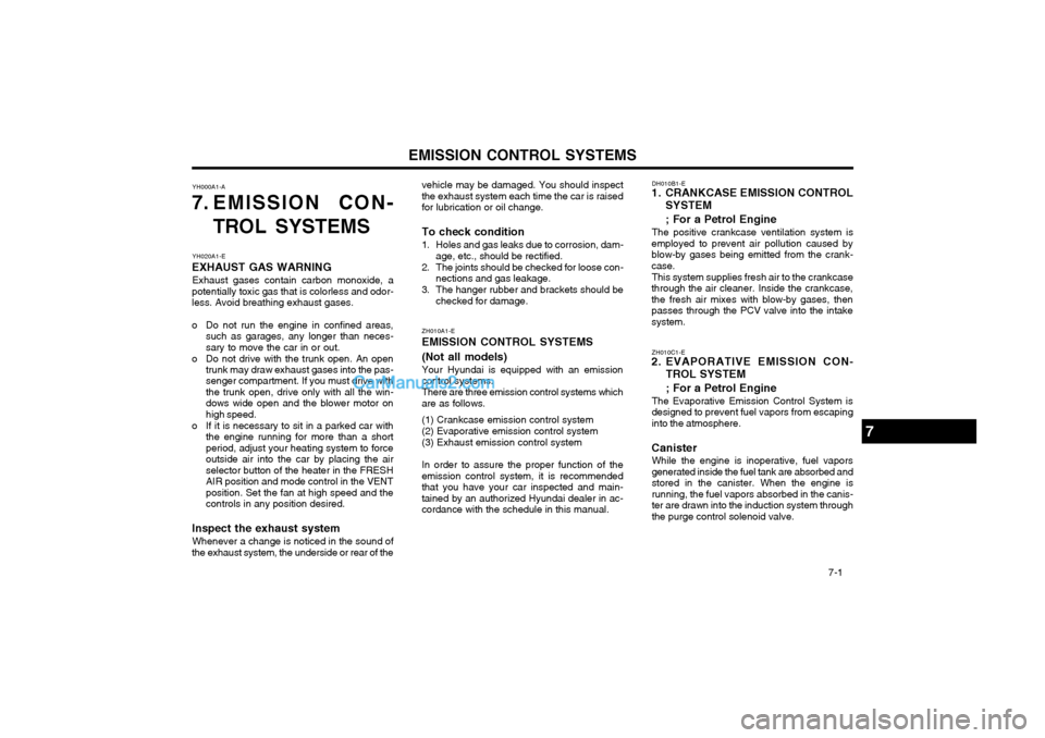
the exhaust system, the underside or rear of the ZH010A1-E EMISSION CONTROL SYSTEMS (Not all models) Your Hyundai is equipped with an emission control systems. There are three emission control systems which are as follows. (1) Crankcase emission control system (2) Evaporative emission control system(3) Exhaust emission control system In order to assure the proper function of the emission control system, it is recommendedthat you have your car inspected and main-tained by an authorized Hyundai dealer in ac-cordance with the schedule in this manual.
7
Page 337 of 349
EMISSION CONTROL SYSTEMS
7-2
Purge Control Solenoid Valve
The purge control solenoid valve is controlled
by the ECU; when the engine coolant tempera- ture is low, and during idling, it closes, so thatevaporated fuel is not taken into the surge tank.After engine warm-up, during ordinary driving, itopens to introduce evaporated fuel to the surgetank. misfire and result in excessive loading of thecatalytic converter.
o Avoid idling the engine for periods longer than 10 minutes.
o Your Hyundai should not be either pushed or pulled to get it started. This can cause thecatalytic converter to overload.
o Take care not to stop your Hyundai over any combustible material such as grass, paper,leaves or rags.
o Do not touch the catalytic converter or any other part of the exhaust system while theengine is running.
o Remember that your Hyundai dealer is your best source of assistance.
JH010D1-E
3. EXHAUST EMISSION CONTROL
SYSTEM
EGR system ; For a Petrol Engine This system helps control oxides of nitrogen byrecirculating a portion of the exhaust gases intothe intake manifold, thereby reducing cylindercombustion temperatures. YH040A2-E
CATALYTIC CONVERTER
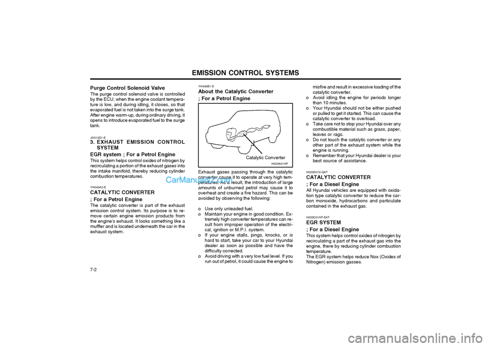
; For a Petrol Engine The catalytic converter is part of the exhaust emission control system. Its purpose is to re-move certain engine emission products fromthe engine's exhaust. It looks something like amuffler and is located underneath the car in theexhaust system. YH040B1-E
About the Catalytic Converter ; For a Petrol Engine
Exhaust gases passing through the catalytic converter cause it to operate at very high tem-peratures. As a result, the introduction of largeamounts of unburned petrol may cause it tooverheat and create a fire hazard. This can beavoided by observing the following:
o Use only unleaded fuel.
o Maintain your engine in good condition. Ex- tremely high converter temperatures can re- sult from improper operation of the electri-cal, ignition or M.P.I. system.
o If your engine stalls, pings, knocks, or is hard to start, take your car to your Hyundaidealer as soon as possible and have thedifficulty corrected.
o Avoid driving with a very low fuel level. If you run out of petrol, it could cause the engine to H020D01S-GAT CATALYTIC CONVERTER ; For a Diesel Engine All Hyundai vehicles are equipped with oxida- tion type catalytic converter to reduce the car-bon monoxide, hydrocarbons and particulatecontained in the exhaust gas. H020C01HP-EAT EGR SYSTEM ; For a Diesel Engine This system helps control oxides of nitrogen by recirculating a part of the exhaust gas into theengine, there by reducing cylinder combustiontemperature. The EGR system helps reduce Nox (Oxides of Nitrogen) emission gasses.
Catalytic ConverterH020A01HP
Page 338 of 349
CONSUMER INFORMATION 8-1
YI000A1-E
8. CONSUMERINFORMATION
8
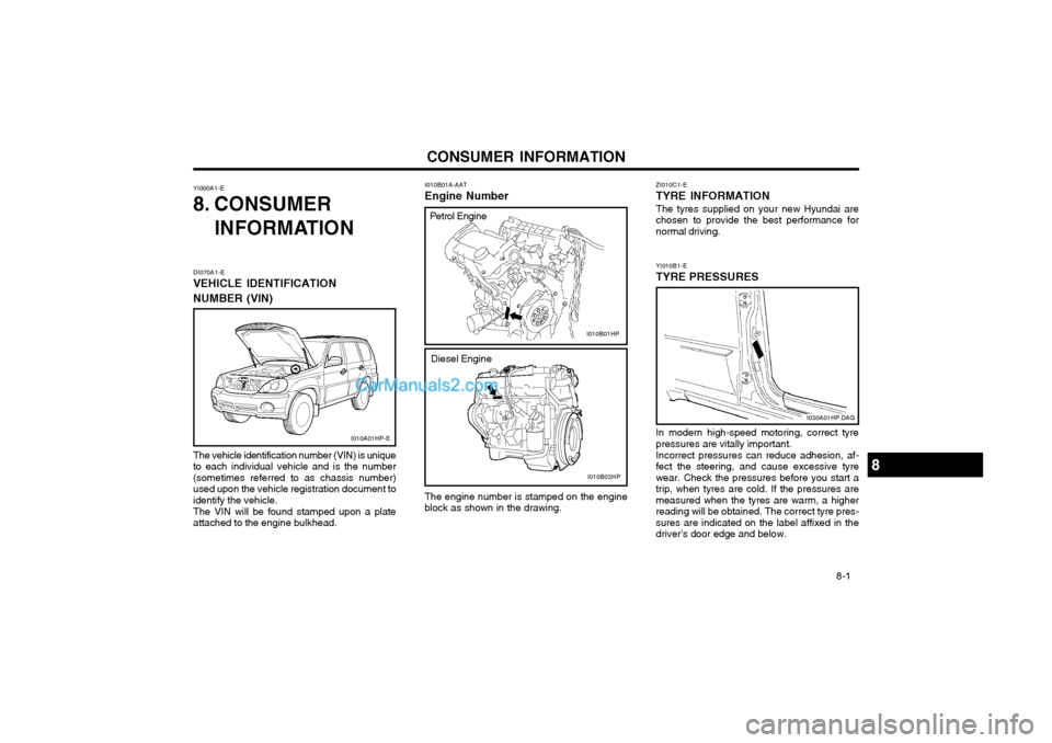
DI070A1-E VEHICLE IDENTIFICATION NUMBER (VIN)
I010A01HP-E
I030A01HP.DAG
I010B03HP
I010B01HP
Petrol Engine
The vehicle identification number (VIN) is unique to each individual vehicle and is the number(sometimes referred to as chassis number)used upon the vehicle registration document toidentify the vehicle. The VIN will be found stamped upon a plate attached to the engine bulkhead. I010B01A-AAT Engine Number The engine number is stamped on the engine block as shown in the drawing.
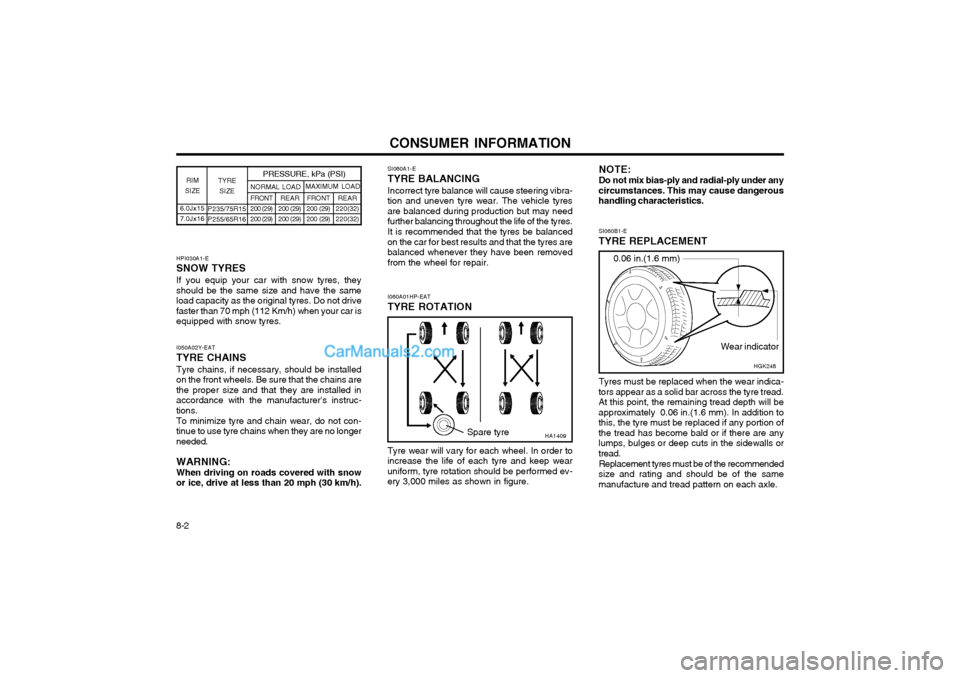
ZI010C1-E TYRE INFORMATION The tyres supplied on your new Hyundai are chosen to provide the best performance fornormal driving. YI010B1-E TYRE PRESSURES In modern high-speed motoring, correct tyre pressures are vitally important. Incorrect pressures can reduce adhesion, af- fect the steering, and cause excessive tyrewear. Check the pressures before you start atrip, when tyres are cold. If the pressures aremeasured when the tyres are warm, a higherreading will be obtained. The correct tyre pres-sures are indicated on the label affixed in thedriver's door edge and below.
Diesel Engine
Page 339 of 349
CONSUMER INFORMATION
8-2 6.0Jx15 7.0Jx16
TYRE
SIZE
RIM
SIZE PRESSURE, kPa (PSI)
P235/75R15P255/65R16 REAR
200 (29)200 (29) FRONT
200 (29)200 (29)
NORMAL LOAD
MAXIMUM LOAD
REAR
220(32)220(32)
FRONT200 (29)200 (29)
SI060A1-E
TYRE BALANCING
Incorrect tyre balance will cause steering vibra-
tion and uneven tyre wear. The vehicle tyres are balanced during production but may needfurther balancing throughout the life of the tyres.
It is recommended that the tyres be balanced
on the car for best results and that the tyres arebalanced whenever they have been removedfrom the wheel for repair.
HPI030A1-E SNOW TYRES If you equip your car with snow tyres, they should be the same size and have the sameload capacity as the original tyres. Do not drivefaster than 70 mph (112 Km/h) when your car isequipped with snow tyres. I050A02Y-EAT TYRE CHAINS Tyre chains, if necessary, should be installed on the front wheels. Be sure that the chains arethe proper size and that they are installed inaccordance with the manufacturer's instruc-tions. To minimize tyre and chain wear, do not con- tinue to use tyre chains when they are no longerneeded. WARNING: When driving on roads covered with snow or ice, drive at less than 20 mph (30 km/h).
HA1409Spare tyre SI060B1-E
TYRE REPLACEMENT
Wear indicator
0.06 in.(1.6 mm)
HGK248
Tyres must be replaced when the wear indica-
tors appear as a solid bar across the tyre tread. At this point, the remaining tread depth will beapproximately 0.06 in.(1.6 mm). In addition tothis, the tyre must be replaced if any portion ofthe tread has become bald or if there are anylumps, bulges or deep cuts in the sidewalls ortread.
Replacement tyres must be of the recommended
size and rating and should be of the samemanufacture and tread pattern on each axle.
I060A01HP-EAT
TYRE ROTATION
Tyre wear will vary for each wheel. In order to
increase the life of each tyre and keep wearuniform, tyre rotation should be performed ev-ery 3,000 miles as shown in figure. NOTE: Do not mix bias-ply and radial-ply under any
circumstances. This may cause dangerous handling characteristics.
Page 340 of 349
CONSUMER INFORMATION 8-3
SI060D2-E WHEEL REPLACEMENT The original wheels may only be replaced with Hyundai Approved wheels. WARNING: Driving on worn or defective tyres is dan- gerous. Worn tyres may cause loss of steer-ing control and a serious deterioration ofbraking efficiency. Defective tyres may causevibration and loss of control through blowouts. Tyres of different size, construction or tread pattern should not be intermixed on the sameaxle. Radial and cross ply tyres should not beused on the same vehicle. The use of tyres and wheels of non approved sizes can be dangerous.
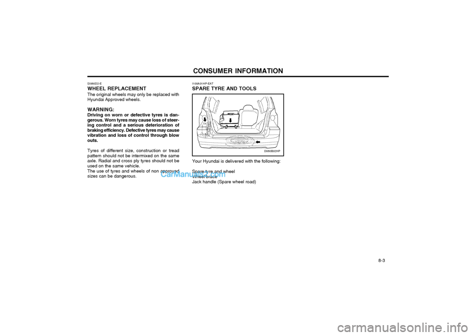
I100A01HP-EAT SPARE TYRE AND TOOLS
D060B02HP
Your Hyundai is delivered with the following: Spare tyre and wheel Wheel braceJack handle (Spare wheel road)