seal INFINITI FX35 2008 Service Manual
[x] Cancel search | Manufacturer: INFINITI, Model Year: 2008, Model line: FX35, Model: INFINITI FX35 2008Pages: 3924, PDF Size: 81.37 MB
Page 3106 of 3924

LT-4
< SERVICE INFORMATION >
PRECAUTIONS
SERVICE INFORMATION
PRECAUTIONS
Precaution for Supplemental Restraint System (SRS) "AIR BAG" and "SEAT BELT
PRE-TENSIONER"
INFOID:0000000001612924
The Supplemental Restraint System such as “A IR BAG” and “SEAT BELT PRE-TENSIONER”, used along
with a front seat belt, helps to reduce the risk or severi ty of injury to the driver and front passenger for certain
types of collision. This system includes seat belt switch inputs and dual stage front air bag modules. The SRS
system uses the seat belt switches to determine the front air bag deployment, and may only deploy one front
air bag, depending on the severity of a collision and w hether the front occupants are belted or unbelted.
Information necessary to service the system safely is included in the “SUPPLEMENTAL RESTRAINT SYS-
TEM” and “SEAT BELTS” of this Service Manual.
WARNING:
• To avoid rendering the SRS inopera tive, which could increase the risk of personal injury or death in
the event of a collision which would result in air bag inflation, all maintenance must be performed by
an authorized NISS AN/INFINITI dealer.
Improper maintenance, including in correct removal and installation of the SRS, can lead to personal
injury caused by unintent ional activation of the system. For re moval of Spiral Cable and Air Bag
Module, see the “SUPPLEMEN TAL RESTRAINT SYSTEM”.
Do not use electrical test equipmen t on any circuit related to the SRS unless instructed to in this
Service Manual. SRS wiring harnesses can be identi fied by yellow and/or orange harnesses or har-
ness connectors.
General Precaution for Service OperationINFOID:0000000001328264
Never work with wet hands.
Xenon headlamp includes high voltage generating part. Be sure to disconnect battery negative cable (negative terminal) or power
fuse before removing, installing, or touching the xenon headlamp
(including lamp bulb).
Turn the lighting switch OFF before disconnecting and connecting the connector.
When turning the xenon headlamp on and while it is illuminated, never touch the harness, bulb, and socket of the headlamp.
When checking the headlamp on/off operation, check it on vehicle
and with the power connected to the vehicle-side connector.
Do not touch the headlamp bulb glass surface with bare hands or allow oil or grease to get on it. Do not touch the headl amp bulb just after the headlamp is turned off, because
it is very hot.
Install the xenon headlamp bulb socket co rrectly. If it is installed improperly, high-voltage leak or corona dis-
charge may occur that can melt the bulb, connecto r, and housing. Do not illuminate the xenon headlamp
bulb out of the headlamp housing. Doing so can cause fire and harm your eyes.
When the bulb has burned out, wrap it in a thick vinyl bag and discard. Do not break the bulb.
Leaving the bulb removed from the headlamp housing for a long period of time can deteriorate the perfor- mance of the lens and reflector (dirt, clouding). Al ways prepare a new bulb and have it on hand when replac-
ing the bulb.
When adjusting the headlamp aiming, turn the aiming adjus tment screw only in the tightening direction. (If it
is necessary to loosen the screw, first fully loosen the screw, and then turn it in the tightening direction.)
Do not use organic solvent (paint thinner or gasoline) to clean lamps and to remove old sealant.
PKID0793E
3AA93ABC3ACD3AC03ACA3AC03AC63AC53A913A773A893A873A873A8E3A773A983AC73AC93AC03AC3
3A893A873A873A8F3A773A9D3AAF3A8A3A8C3A863A9D3AAF3A8B3A8C
Page 3132 of 3924

LT-30
< SERVICE INFORMATION >
HEADLAMP - XENON TYPE -
After installing bulb, be sure to install plastic cap and bulb socket securely to insure watertight-
ness.
Removal and InstallationINFOID:0000000001328289
REMOVAL
1. Disconnect the battery cable from the negative terminal or remove power fuse.
2. Remove front bumper fascia assembly. Refer to EI-14, "
Compo-
nent Parts Location".
3. Remove headlamp mounting bolts and nut.
4. Remove plastics bumper bracket, then pull headlamp toward vehicle front, disconnect connector, and remove headlamp.
INSTALLATION
Installation is the reverse order of removal.
NOTE:
After installation, perform aiming adjustment. Refer to LT-27, "
Aiming Adjustment".
Disassembly and AssemblyINFOID:0000000001328290
DISASSEMBLY
1. Turn plastic cap counterclockwise and unlock it.
SKIA5553E
Headlamp mounting bolt : 6.1 N·m (0.62 kg-m, 54 in-lb)
1. Side marker lamp bulb 2. Side marker lamp bulb socket 3. Front turn signal lamp bulb socket
4. Front turn signal lamp bulb 5. Seal packing 6. Plastic cap
7. Xenon bulb (high/low) 8. Xenon bulb socket (high/low) 9. HID control unit cover mounting screw
10. HID control unit cover 11. HID control unit mounting screw 12. HID control unit
13. Seal packing 14. Daytime/Parking lamp bulb socket 15. Daytime/Parking lamp bulb
16. Headlamp housing assembly 17. Retaining spring
:Alway replace after every disassembly
:N·m (kg-m, in-lb)
PKIC9685E
3AA93ABC3ACD3AC03ACA3AC03AC63AC53A913A773A893A873A873A8E3A773A983AC73AC93AC03AC3
3A893A873A873A8F3A773A9D3AAF3A8A3A8C3A863A9D3AAF3A8B3A8C
Page 3177 of 3924

FRONT FOG LAMPLT-75
< SERVICE INFORMATION >
C
DE
F
G H
I
J
L
M A
B
LT
N
O P
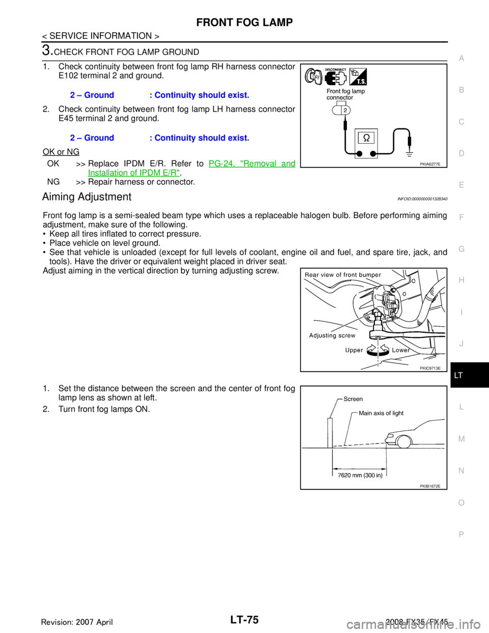
3.CHECK FRONT FOG LAMP GROUND
1. Check continuity between front fog lamp RH harness connector E102 terminal 2 and ground.
2. Check continuity between front fog lamp LH harness connector E45 terminal 2 and ground.
OK or NG
OK >> Replace IPDM E/R. Refer to PG-24, "Removal and
Installation of IPDM E/R".
NG >> Repair harness or connector.
Aiming AdjustmentINFOID:0000000001328340
Front fog lamp is a semi-sealed beam type which uses a replaceable halogen bulb. Before performing aiming
adjustment, make sure of the following.
Keep all tires inflated to correct pressure.
Place vehicle on level ground.
See that vehicle is unloaded (except for full levels of coolant, engine oil and fuel, and spare tire, jack, and tools). Have the driver or equivalent weight placed in driver seat.
Adjust aiming in the vertical direction by turning adjusting screw.
1. Set the distance between the scr een and the center of front fog
lamp lens as shown at left.
2. Turn front fog lamps ON. 2 – Ground : Continuity should exist.
2 – Ground : Continuity should exist.
PKIA6277E
PKIC9713E
PKIB1672E
3AA93ABC3ACD3AC03ACA3AC03AC63AC53A913A773A893A873A873A8E3A773A983AC73AC93AC03AC3
3A893A873A873A8F3A773A9D3AAF3A8A3A8C3A863A9D3AAF3A8B3A8C
Page 3217 of 3924

STOP LAMPLT-115
< SERVICE INFORMATION >
C
DE
F
G H
I
J
L
M A
B
LT
N
O P
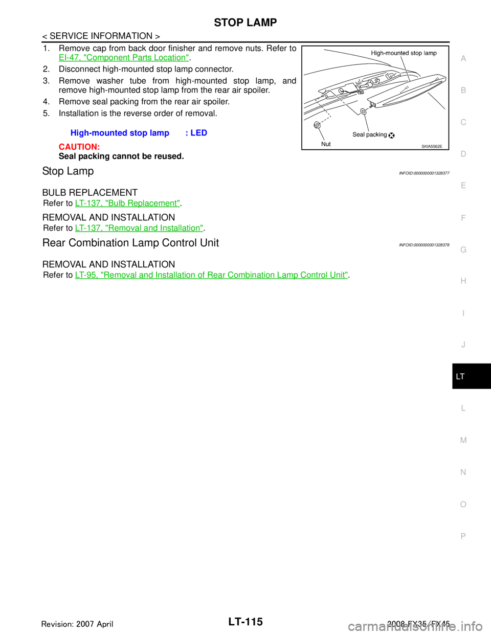
1. Remove cap from back door finisher and remove nuts. Refer to EI-47, "
Component Parts Location".
2. Disconnect high-mounted stop lamp connector.
3. Remove washer tube from high-mounted stop lamp, and remove high-mounted stop lamp from the rear air spoiler.
4. Remove seal packing from the rear air spoiler.
5. Installation is the reverse order of removal.
CAUTION:
Seal packing cannot be reused.
Stop LampINFOID:0000000001328377
BULB REPLACEMENT
Refer to LT-137, "Bulb Replacement".
REMOVAL AND INSTALLATION
Refer to LT-137, "Removal and Installation".
Rear Combination Lamp Control UnitINFOID:0000000001328378
REMOVAL AND INSTALLATION
Refer to LT-95, "Removal and Installation of Rear Combination Lamp Control Unit".
High-mounted stop lamp : LED
SKIA5562E
3AA93ABC3ACD3AC03ACA3AC03AC63AC53A913A773A893A873A873A8E3A773A983AC73AC93AC03AC3
3A893A873A873A8F3A773A9D3AAF3A8A3A8C3A863A9D3AAF3A8B3A8C
Page 3219 of 3924

BACK-UP LAMPLT-117
< SERVICE INFORMATION >
C
DE
F
G H
I
J
L
M A
B
LT
N
O P
Bulb ReplacementINFOID:0000000001328380
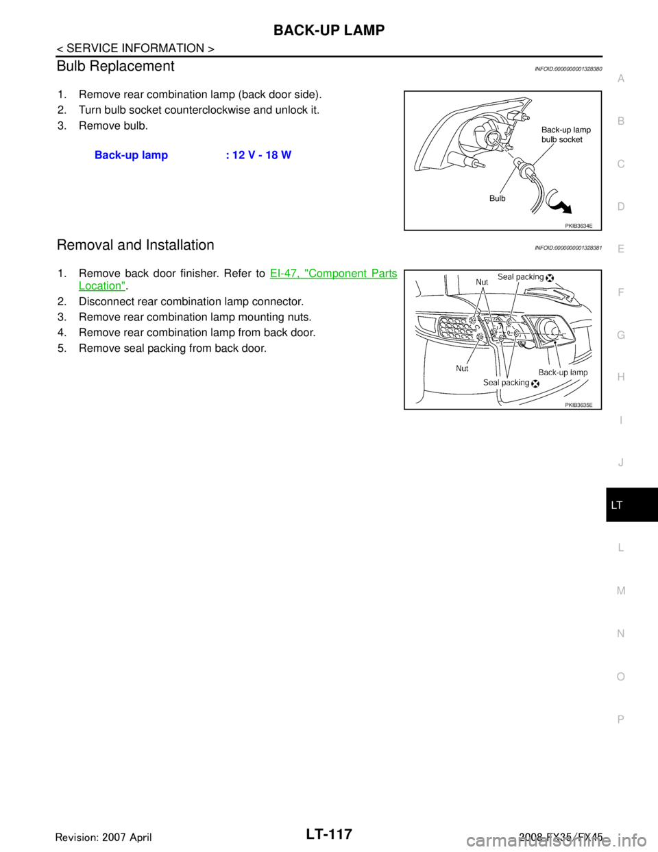
1. Remove rear combination lamp (back door side).
2. Turn bulb socket counterclockwise and unlock it.
3. Remove bulb.
Removal and InstallationINFOID:0000000001328381
1. Remove back door finisher. Refer to EI-47, "Component Parts
Location".
2. Disconnect rear combination lamp connector.
3. Remove rear combination lamp mounting nuts.
4. Remove rear combination lamp from back door.
5. Remove seal packing from back door. Back-up lamp : 12 V - 18 W
PKIB3634E
PKIB3635E
3AA93ABC3ACD3AC03ACA3AC03AC63AC53A913A773A893A873A873A8E3A773A983AC73AC93AC03AC3
3A893A873A873A8F3A773A9D3AAF3A8A3A8C3A863A9D3AAF3A8B3A8C
Page 3239 of 3924

REAR COMBINATION LAMPLT-137
< SERVICE INFORMATION >
C
DE
F
G H
I
J
L
M A
B
LT
N
O P
REAR COMBINATION LAMP
Bulb ReplacementINFOID:0000000001328404
REAR FENDER SIDE (REAR SIDE MARKER LAMP BULB)
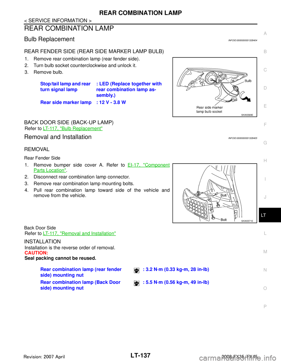
1. Remove rear combination lamp (rear fender side).
2. Turn bulb socket counterclockwise and unlock it.
3. Remove bulb.
BACK DOOR SIDE (BACK-UP LAMP)
Refer to LT-117, "Bulb Replacement"
Removal and InstallationINFOID:0000000001328405
REMOVAL
Rear Fender Side
1. Remove bumper side cover A. Refer to EI-17, "Component
Parts Location".
2. Disconnect rear combination lamp connector.
3. Remove rear combination lamp mounting bolts.
4. Pull rear combination lamp toward side of the vehicle and remove from the vehicle.
Back Door Side
Refer to LT-117, "Removal and Installation"
INSTALLATION
Installation is the reverse order of removal.
CAUTION:
Seal packing cannot be reused.Stop/tail lamp and rear
turn signal lamp
: LED (Replace together with
rear combination lamp as-
sembly.)
Rear side marker lamp : 12 V - 3.8 W
SKIA5569E
SKIA5571E
Rear combination lamp (rear fender
side) mounting nut : 3.2 N·m (0.33 kg-m, 28 in-lb)
Rear combination lamp (Back Door
side) mounting nut : 5.5 N·m (0.56 kg-m, 49 in-lb)
3AA93ABC3ACD3AC03ACA3AC03AC63AC53A913A773A893A873A873A8E3A773A983AC73AC93AC03AC3
3A893A873A873A8F3A773A9D3AAF3A8A3A8C3A863A9D3AAF3A8B3A8C
Page 3287 of 3924
![INFINITI FX35 2008 Service Manual
LU-2
< SERVICE INFORMATION >[VQ35DE]
PRECAUTIONS
SERVICE INFORMATION
PRECAUTIONS
Precaution for Liquid GasketINFOID:0000000001325808
LIQUID GASKET APPLICATION PROCEDURE
1. Remove old liquid gasket ad INFINITI FX35 2008 Service Manual
LU-2
< SERVICE INFORMATION >[VQ35DE]
PRECAUTIONS
SERVICE INFORMATION
PRECAUTIONS
Precaution for Liquid GasketINFOID:0000000001325808
LIQUID GASKET APPLICATION PROCEDURE
1. Remove old liquid gasket ad](/img/42/57017/w960_57017-3286.png)
LU-2
< SERVICE INFORMATION >[VQ35DE]
PRECAUTIONS
SERVICE INFORMATION
PRECAUTIONS
Precaution for Liquid GasketINFOID:0000000001325808
LIQUID GASKET APPLICATION PROCEDURE
1. Remove old liquid gasket adhering to the liquid gasket application surface and the mating surface.
• Remove liquid gasket completely from the liquid gasket application surface, mounting bolts, and boltholes.
2. Wipe the liquid gasket application surface and the ma ting surface with white gasoline (lighting and heating
use) to remove adhering moisture, grease and foreign materials.
3. Apply liquid gasket to the liquid gasket application surface. Use Genuine RTV Silicone Seal ant or equivalent. Refer to GI-44
.
Within five minutes of liquid gasket application, install the mating component.
If liquid gasket protrudes, wipe it off immediately.
Do not retighten after mounting bolts and nuts the installation.
After 30 minutes or more have passed from the installation, fill engine oil and engine coolant.
3AA93ABC3ACD3AC03ACA3AC03AC63AC53A913A773A893A873A873A8E3A773A983AC73AC93AC03AC3
3A893A873A873A8F3A773A9D3AAF3A8A3A8C3A863A9D3AAF3A8B3A8C
Page 3290 of 3924
![INFINITI FX35 2008 Service Manual
ENGINE OILLU-5
< SERVICE INFORMATION > [VQ35DE]
C
D
E
F
G H
I
J
K L
M A
LU
NP
O
ENGINE OIL
InspectionINFOID:0000000001325813
ENGINE OIL LEVEL
NOTE:
Before starting engine, put vehicle horizontally an INFINITI FX35 2008 Service Manual
ENGINE OILLU-5
< SERVICE INFORMATION > [VQ35DE]
C
D
E
F
G H
I
J
K L
M A
LU
NP
O
ENGINE OIL
InspectionINFOID:0000000001325813
ENGINE OIL LEVEL
NOTE:
Before starting engine, put vehicle horizontally an](/img/42/57017/w960_57017-3289.png)
ENGINE OILLU-5
< SERVICE INFORMATION > [VQ35DE]
C
D
E
F
G H
I
J
K L
M A
LU
NP
O
ENGINE OIL
InspectionINFOID:0000000001325813
ENGINE OIL LEVEL
NOTE:
Before starting engine, put vehicle horizontally and check
the engine oil level. If engine is already started, stop
it and allow 10 minutes before checking.
1. Pull out oil level gauge and wipe it clean.
2. Insert oil level gauge and make sure the engine oil level is within the range shown in the figure.
3. If it is out of range, adjust it.
NOTE:
When checking the engine oil level, insert oil level gauge with its
tip aligned with oil level gauge guide on cylinder head. (In figure,
air cleaner case and air duct are removed.)
ENGINE OIL APPEARANCE
Check engine oil for white turbidity or heavy contamination.
If engine oil becomes turbid and white, it is highl y probable that it is contaminated with engine coolant.
Repair or replace damaged parts.
ENGINE OIL LEAKAGE
Check for engine oil leakage around the following areas:
Oil pans (lower and upper)
Oil pan drain plug
Oil pressure switch
Oil filter
Oil filter bracket (AWD models)
Oil cooler
Water pump cover
Chain tensioner cover
Intake valve timing control cover and intake valve timing control solenoid valve
Mating surface between cylinder head and rocker cover
Mating surface between front timing chain case and rear timing chain case
Mating surface between rear timing chain case and cylinder head
Mating surface between rear timing chain case and cylinder block
Mating surface between rear timing chain case and oil pan (upper)
Mating surface between cylinder block and cylinder head
Crankshaft oil seals (front and rear)
Camshaft position sensor (PHASE)
OIL PRESSURE CHECK
PBIC3101E
KBIA1343E
3AA93ABC3ACD3AC03ACA3AC03AC63AC53A913A773A893A873A873A8E3A773A983AC73AC93AC03AC3
3A893A873A873A8F3A773A9D3AAF3A8A3A8C3A863A9D3AAF3A8B3A8C
Page 3291 of 3924
![INFINITI FX35 2008 Service Manual
LU-6
< SERVICE INFORMATION >[VQ35DE]
ENGINE OIL
WARNING:
• Be careful not to get burn your
self, as engine oil may be hot.
Oil pressure check should be done in “Parking position”.
1. Check t INFINITI FX35 2008 Service Manual
LU-6
< SERVICE INFORMATION >[VQ35DE]
ENGINE OIL
WARNING:
• Be careful not to get burn your
self, as engine oil may be hot.
Oil pressure check should be done in “Parking position”.
1. Check t](/img/42/57017/w960_57017-3290.png)
LU-6
< SERVICE INFORMATION >[VQ35DE]
ENGINE OIL
WARNING:
• Be careful not to get burn your
self, as engine oil may be hot.
Oil pressure check should be done in “Parking position”.
1. Check the engine oil level. Refer to "ENGINE OIL LEVEL".
2. Remove front engine undercover with power tool.
3. Disconnect harness connector at oil pressure sensor, and remove oil pressure sensor using deep socket (commercial ser-
vice tool).
CAUTION:
Do not drop or shock oil pressure switch.
4. Install the oil pressure gauge (SST) and hose (SST).
5. Start the engine and warm it up to normal operating temperature.
6. Check the engine oil pressure with engine running under no-load. NOTE:
When the engine oil temperature is low, the engine oil pressure becomes high.
Engine oil pressure [Engi ne oil temperature at 80 °C (176 °F)]
Unit: kPa (kg/cm2, psi)
If difference is extreme, check engine oil passage and oil pump for engine oil leaks.
7. After the inspections, install oil pressure switch as follows:
a. Remove old liquid gasket adhering to oil pressure switch and the mating surface.
b. Apply liquid gasket and tighten oil pressure switch to the specification. Use Genuine RTV Silicone Seal ant or equivalent. Refer to GI-44, "
Recommended Chemical Prod-
uct and Sealant".
SBIA0452E
SBIA0453E
SLC926
Engine speed Approximate discharge pressure
Idle speed More than 98 (1.0, 14)2,000 rpm More than 294 (3.0, 43)
3AA93ABC3ACD3AC03ACA3AC03AC63AC53A913A773A893A873A873A8E3A773A983AC73AC93AC03AC3
3A893A873A873A8F3A773A9D3AAF3A8A3A8C3A863A9D3AAF3A8B3A8C
Page 3293 of 3924
![INFINITI FX35 2008 Service Manual
LU-8
< SERVICE INFORMATION >[VQ35DE]
OIL FILTER
OIL FILTER
Removal and InstallationINFOID:0000000001325815
REMOVAL
1. Remove front engine undercover with power tool.
2. Using oil filter wrench (SST), INFINITI FX35 2008 Service Manual
LU-8
< SERVICE INFORMATION >[VQ35DE]
OIL FILTER
OIL FILTER
Removal and InstallationINFOID:0000000001325815
REMOVAL
1. Remove front engine undercover with power tool.
2. Using oil filter wrench (SST),](/img/42/57017/w960_57017-3292.png)
LU-8
< SERVICE INFORMATION >[VQ35DE]
OIL FILTER
OIL FILTER
Removal and InstallationINFOID:0000000001325815
REMOVAL
1. Remove front engine undercover with power tool.
2. Using oil filter wrench (SST), remove oil filter.
CAUTION:
Oil filter is provided with relief valve. Use Genuine NissanOil Filter or equivalent.
Be careful not to get burned when engine and engine oil may be hot.
When removing, prepare a sh op cloth to absorb any
engine oil leakage or spillage.
Do not allow engine oil to adhere to drive belts.
Completely wipe off any engine oil that adheres to engine
and vehicle.
INSTALLATION
1. Remove foreign materials adhering to oil filter installation surface.
2. Apply engine oil to the oil seal contact surface of new oil filter.
3. Screw oil filter manually until it touches the installation surface,
then tighten it by 2/3 turn. Or tighten to the specification.
INSPECTION AFTER INSTALLATION
1. Check the engine oil level. Refer to LU-5, "Inspection".
SBIA0454E
SBIA0455E
SMA010
Oil filter:
: 17.7 N·m (1.8 kg-m, 13 ft-lb)
SMA229B
3AA93ABC3ACD3AC03ACA3AC03AC63AC53A913A773A893A873A873A8E3A773A983AC73AC93AC03AC3
3A893A873A873A8F3A773A9D3AAF3A8A3A8C3A863A9D3AAF3A8B3A8C