seal INFINITI FX35 2008 Service Manual
[x] Cancel search | Manufacturer: INFINITI, Model Year: 2008, Model line: FX35, Model: INFINITI FX35 2008Pages: 3924, PDF Size: 81.37 MB
Page 2815 of 3924
FFD-24
< SERVICE INFORMATION >
FRONT FINAL DRIVE ASSEMBLY
b. If the runout value is still outside of the limit after the phase has been changed, possible cause will be an
assembly malfunction of drive pinion and pinion bearing and malfunction of pinion bearing. Check for
these items and repair if necessary.
c. If the runout value is still outside of the limit after the check and repair, replace companion flange.
DISASSEMBLY
Side Shaft Assembly
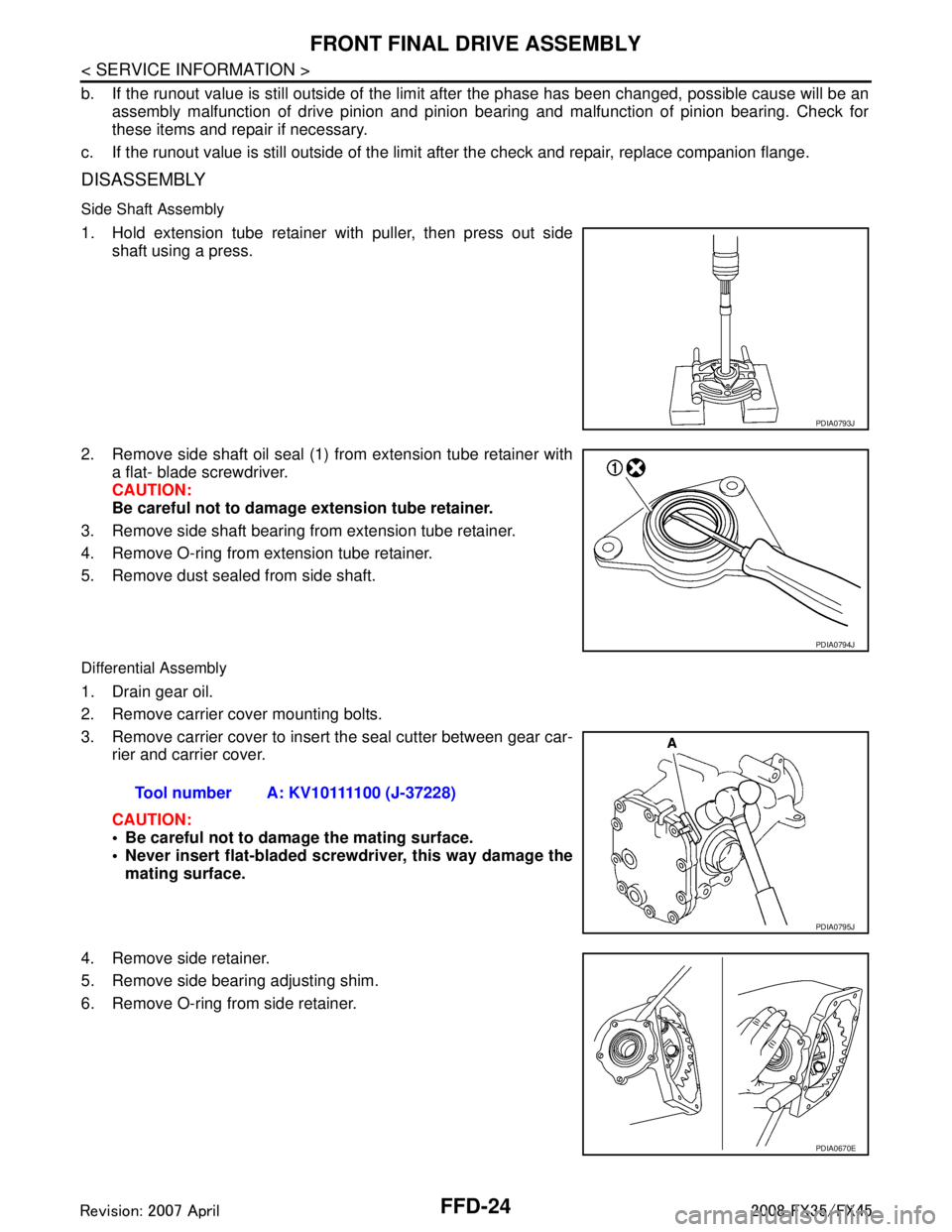
1. Hold extension tube retainer with puller, then press out side shaft using a press.
2. Remove side shaft oil seal (1) from extension tube retainer with a flat- blade screwdriver.
CAUTION:
Be careful not to damage extension tube retainer.
3. Remove side shaft bearing from extension tube retainer.
4. Remove O-ring from extension tube retainer.
5. Remove dust sealed from side shaft.
Differential Assembly
1. Drain gear oil.
2. Remove carrier cover mounting bolts.
3. Remove carrier cover to insert the seal cutter between gear car- rier and carrier cover.
CAUTION:
Be careful not to damage the mating surface.
Never insert flat-bladed screwdriver, this way damage the
mating surface.
4. Remove side retainer.
5. Remove side bearing adjusting shim.
6. Remove O-ring from side retainer.
PDIA0793J
PDIA0794J
Tool number A: KV10111100 (J-37228)
PDIA0795J
PDIA0670E
3AA93ABC3ACD3AC03ACA3AC03AC63AC53A913A773A893A873A873A8E3A773A983AC73AC93AC03AC3
3A893A873A873A8F3A773A9D3AAF3A8A3A8C3A863A9D3AAF3A8B3A8C
Page 2816 of 3924
FRONT FINAL DRIVE ASSEMBLYFFD-25
< SERVICE INFORMATION >
CEF
G H
I
J
K L
M A
B
FFD
N
O P
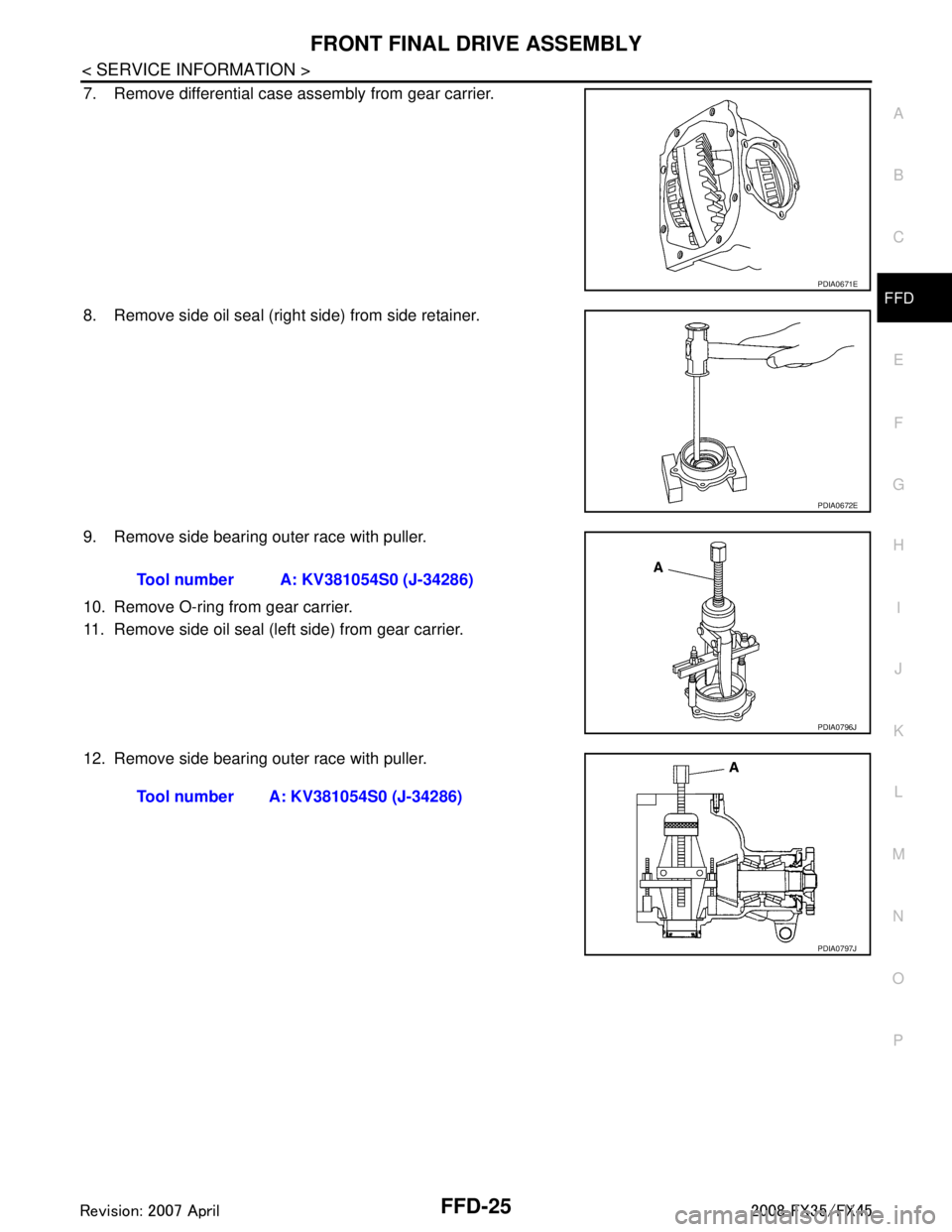
7. Remove differential case assembly from gear carrier.
8. Remove side oil seal (right side) from side retainer.
9. Remove side bearing outer race with puller.
10. Remove O-ring from gear carrier.
11. Remove side oil seal (left side) from gear carrier.
12. Remove side bearing outer race with puller.
PDIA0671E
PDIA0672E
Tool number A: KV381054S0 (J-34286)
PDIA0796J
Tool number A: KV381054S0 (J-34286)
PDIA0797J
3AA93ABC3ACD3AC03ACA3AC03AC63AC53A913A773A893A873A873A8E3A773A983AC73AC93AC03AC3
3A893A873A873A8F3A773A9D3AAF3A8A3A8C3A863A9D3AAF3A8B3A8C
Page 2819 of 3924
FFD-28
< SERVICE INFORMATION >
FRONT FINAL DRIVE ASSEMBLY
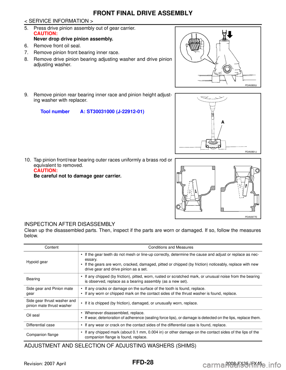
5. Press drive pinion assembly out of gear carrier.CAUTION:
Never drop drive pinion assembly.
6. Remove front oil seal.
7. Remove pinion front bearing inner race.
8. Remove drive pinion bearing adjusting washer and drive pinion adjusting washer.
9. Remove pinion rear bearing inner race and pinion height adjust- ing washer with replacer.
10. Tap pinion front/rear bearing outer races uniformly a brass rod or equivalent to removed.
CAUTION:
Be careful not to damage gear carrier.
INSPECTION AFTER DISASSEMBLY
Clean up the disassembled parts. Then, inspect if the parts are worn or damaged. If so, follow the measures
below.
ADJUSTMENT AND SELECTION OF ADJUSTING WASHERS (SHIMS)
PDIA0800J
Tool number A: ST30031000 (J-22912-01)
PDIA0801J
PDIA0677E
Content Conditions and Measures
Hypoid gear If the gear teeth do not mesh or line-up correctly, determine the cause and adjust or replace as nec-
essary.
If the gears are worn, cracked, damaged, pitted or chipped (by friction) noticeably, replace with new drive gear and drive pinion as a set.
Bearing If any chipped (by friction), pitted, worn, rusted or scratched mark, or unusual noise from the bearing
is observed, replace as a bearing assembly (as a new set).
Side gear and Pinion mate
gear If any cracks or damage on the surface of the tooth is found, replace.
If any worn or chipped mark on the contact sides of the thrust washer is found, replace.
Side gear thrust washer and
pinion mate thrust washer If it is chipped (by friction), damaged, or unusually worn, replace.
Oil seal Whenever disassembled, replace.
If wear, deterioration of adherence (sealing force lips), or damage is detected on the lips, replace them.
Differential case If any wear or crack on the contact sides of the differential case is found, replace.
Companion flange If any chipped mark (about 0.1 mm, 0.004 in) or other damage on the contact sides of the lips of the
companion flange is found, replace.
3AA93ABC3ACD3AC03ACA3AC03AC63AC53A913A773A893A873A873A8E3A773A983AC73AC93AC03AC3
3A893A873A873A8F3A773A9D3AAF3A8A3A8C3A863A9D3AAF3A8B3A8C
Page 2824 of 3924
FRONT FINAL DRIVE ASSEMBLYFFD-33
< SERVICE INFORMATION >
CEF
G H
I
J
K L
M A
B
FFD
N
O P
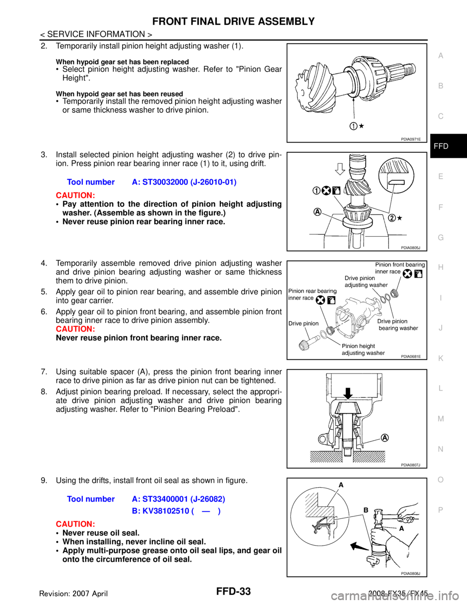
2. Temporarily install pinion height adjusting washer (1).
When hypoid gear se t has been replaced Select pinion height adjusting washer. Refer to "Pinion Gear
Height".
When hypoid gear set has been reused Temporarily install the removed pinion height adjusting washer
or same thickness washer to drive pinion.
3. Install selected pinion height adjusting washer (2) to drive pin- ion. Press pinion rear bearing inner race (1) to it, using drift.
CAUTION:
Pay attention to the direction of pinion height adjusting
washer. (Assemble as shown in the figure.)
Never reuse pinion rear bearing inner race.
4. Temporarily assemble removed drive pinion adjusting washer and drive pinion bearing adjusting washer or same thickness
them to drive pinion.
5. Apply gear oil to pinion rear bearing, and assemble drive pinion into gear carrier.
6. Apply gear oil to pinion front bearing, and assemble pinion front bearing inner race to drive pinion assembly.
CAUTION:
Never reuse pinion front bearing inner race.
7. Using suitable spacer (A), press the pinion front bearing inner race to drive pinion as far as drive pinion nut can be tightened.
8. Adjust pinion bearing preload. If necessary, select the appropri- ate drive pinion adjusting washer and drive pinion bearing
adjusting washer. Refer to "Pinion Bearing Preload".
9. Using the drifts, install front oil seal as shown in figure. CAUTION:
Never reuse oil seal.
When installing, never incline oil seal.
Apply multi-purpose grease onto oil seal lips, and gear oilonto the circumference of oil seal.
PDIA0971E
Tool number A: ST30032000 (J-26010-01)
PDIA0805J
PDIA0681E
PDIA0807J
Tool number A: ST33400001 (J-26082)
B: KV38102510 ( — )
PDIA0808J
3AA93ABC3ACD3AC03ACA3AC03AC63AC53A913A773A893A873A873A8E3A773A983AC73AC93AC03AC3
3A893A873A873A8F3A773A9D3AAF3A8A3A8C3A863A9D3AAF3A8B3A8C
Page 2826 of 3924
FRONT FINAL DRIVE ASSEMBLYFFD-35
< SERVICE INFORMATION >
CEF
G H
I
J
K L
M A
B
FFD
N
O P
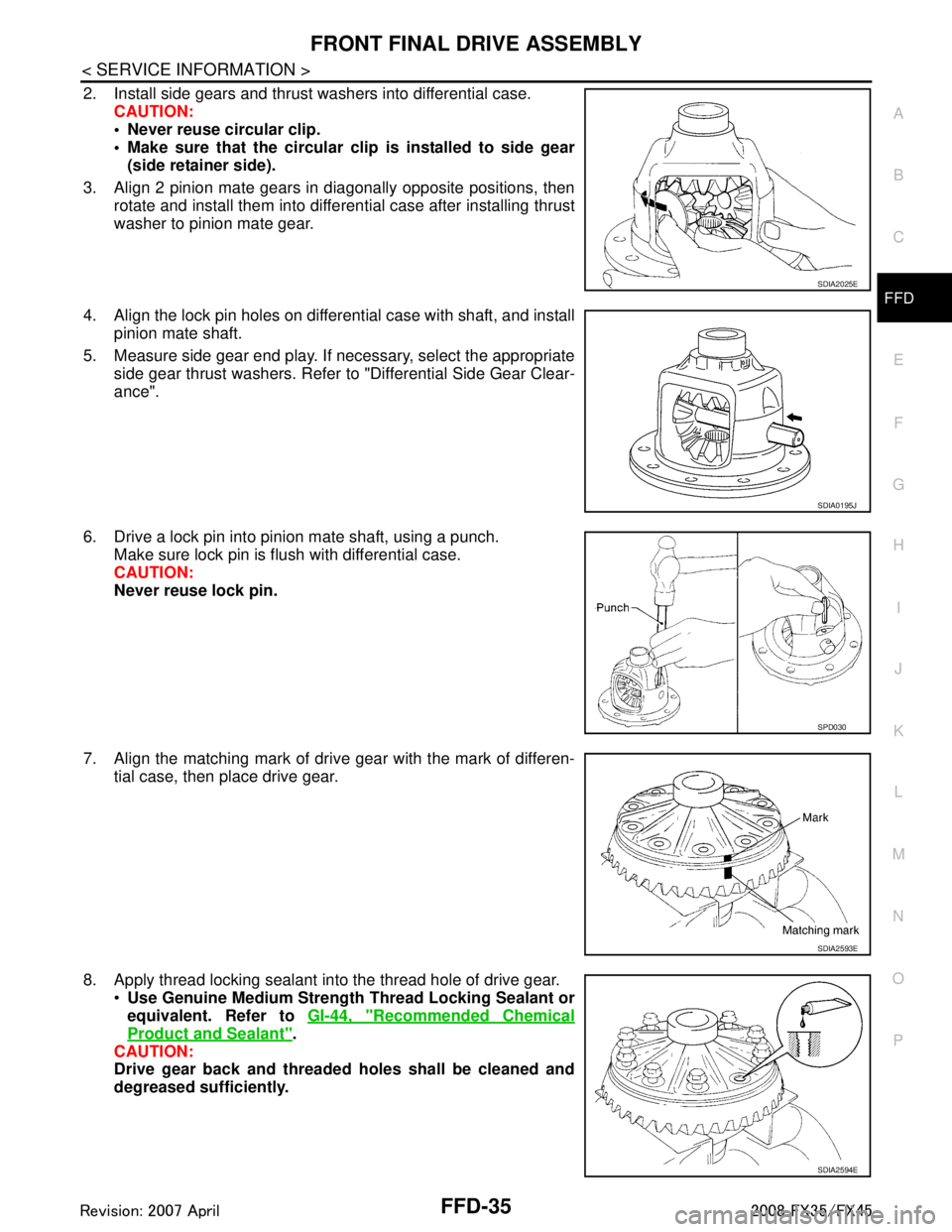
2. Install side gears and thrust washers into differential case. CAUTION:
Never reuse circular clip.
Make sure that the circular cl ip is installed to side gear
(side retainer side).
3. Align 2 pinion mate gears in diagonally opposite positions, then rotate and install them into differential case after installing thrust
washer to pinion mate gear.
4. Align the lock pin holes on differential case with shaft, and install pinion mate shaft.
5. Measure side gear end play. If necessary, select the appropriate side gear thrust washers. Refer to "Differential Side Gear Clear-
ance".
6. Drive a lock pin into pinion mate shaft, using a punch. Make sure lock pin is flush with differential case.
CAUTION:
Never reuse lock pin.
7. Align the matching mark of drive gear with the mark of differen- tial case, then place drive gear.
8. Apply thread locking sealant into the thread hole of drive gear. Use Genuine Medium Strength Thread Locking Sealant or
equivalent. Refer to GI-44, "
Recommended Chemical
Product and Sealant".
CAUTION:
Drive gear back and threaded holes shall be cleaned and
degreased sufficiently.
SDIA2025E
SDIA0195J
SPD030
SDIA2593E
SDIA2594E
3AA93ABC3ACD3AC03ACA3AC03AC63AC53A913A773A893A873A873A8E3A773A983AC73AC93AC03AC3
3A893A873A873A8F3A773A9D3AAF3A8A3A8C3A863A9D3AAF3A8B3A8C
Page 2828 of 3924
FRONT FINAL DRIVE ASSEMBLYFFD-37
< SERVICE INFORMATION >
CEF
G H
I
J
K L
M A
B
FFD
N
O P
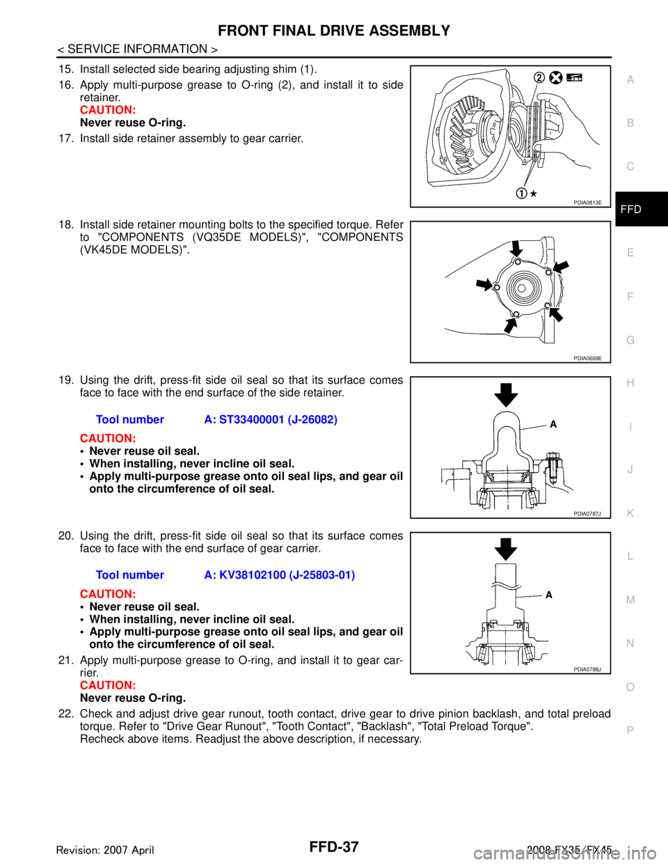
15. Install selected side bearing adjusting shim (1).
16. Apply multi-purpose grease to O-ring (2), and install it to side retainer.
CAUTION:
Never reuse O-ring.
17. Install side retainer assembly to gear carrier.
18. Install side retainer mounting bolts to the specified torque. Refer to "COMPONENTS (VQ35DE MODELS)", "COMPONENTS
(VK45DE MODELS)".
19. Using the drift, press-fit side oil seal so that its surface comes face to face with the end surface of the side retainer.
CAUTION:
Never reuse oil seal.
When installing, never incline oil seal.
Apply multi-purpose grease onto oil seal lips, and gear oilonto the circumference of oil seal.
20. Using the drift, press-fit side oil seal so that its surface comes face to face with the end surface of gear carrier.
CAUTION:
Never reuse oil seal.
When installing, never incline oil seal.
Apply multi-purpose grease onto oil seal lips, and gear oilonto the circumference of oil seal.
21. Apply multi-purpose grease to O-ring, and install it to gear car- rier.
CAUTION:
Never reuse O-ring.
22. Check and adjust drive gear runout, tooth contact, dr ive gear to drive pinion backlash, and total preload
torque. Refer to "Drive Gear Runout", "Tooth Contact", "Backlash", "Total Preload Torque".
Recheck above items. Readjust the above description, if necessary.
PDIA0813E
PDIA0669E
Tool number A: ST33400001 (J-26082)
PDIA0787J
Tool number A: KV38102100 (J-25803-01)
PDIA0788J
3AA93ABC3ACD3AC03ACA3AC03AC63AC53A913A773A893A873A873A8E3A773A983AC73AC93AC03AC3
3A893A873A873A8F3A773A9D3AAF3A8A3A8C3A863A9D3AAF3A8B3A8C
Page 2829 of 3924
FFD-38
< SERVICE INFORMATION >
FRONT FINAL DRIVE ASSEMBLY
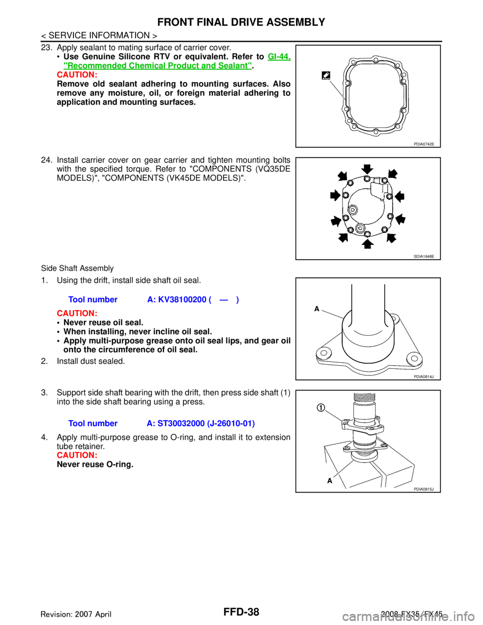
23. Apply sealant to mating surface of carrier cover.Use Genuine Silicone RTV or equivalent. Refer to GI-44,
"Recommended Chemical Product and Sealant".
CAUTION:
Remove old sealant adhering to mounting surfaces. Also
remove any moisture, oil, or foreign material adhering to
application and mounting surfaces.
24. Install carrier cover on gear carrier and tighten mounting bolts with the specified torque. Refer to "COMPONENTS (VQ35DE
MODELS)", "COMPONENT S (VK45DE MODELS)".
Side Shaft Assembly
1. Using the drift, install side shaft oil seal.
CAUTION:
Never reuse oil seal.
When installing, n ever incline oil seal.
Apply multi-purpose grease onto oil seal lips, and gear oil
onto the circumference of oil seal.
2. Install dust sealed.
3. Support side shaft bearing with the drift, then press side shaft (1) into the side shaft bearing using a press.
4. Apply multi-purpose grease to O-ring, and install it to extension tube retainer.
CAUTION:
Never reuse O-ring.
PDIA0742E
SDIA1648E
Tool number A: KV38100200 ( — )
PDIA0814J
Tool number A: ST30032000 (J-26010-01)
PDIA0815J
3AA93ABC3ACD3AC03ACA3AC03AC63AC53A913A773A893A873A873A8E3A773A983AC73AC93AC03AC3
3A893A873A873A8F3A773A9D3AAF3A8A3A8C3A863A9D3AAF3A8B3A8C
Page 2855 of 3924
COIL SPRING AND STRUTFSU-11
< SERVICE INFORMATION >
C
DF
G H
I
J
K L
M A
B
FSU
N
O P
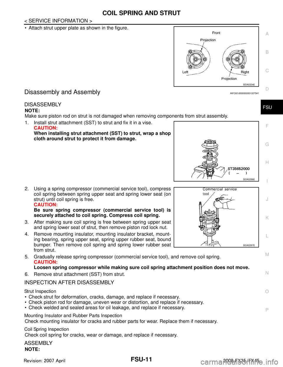
Attach strut upper plate as shown in the figure.
Disassembly and AssemblyINFOID:0000000001327541
DISASSEMBLY
NOTE:
Make sure piston rod on strut is not damaged when removing components from strut assembly.
1. Install strut attachment (SST) to strut and fix it in a vise. CAUTION:
When installing strut attachment (SST) to strut, wrap a shop
cloth around strut to protect it from damage.
2. Using a spring compressor (commercial service tool), compress coil spring between spring upper seat and spring lower seat (on
strut) until coil spring is free.
CAUTION:
Be sure spring compressor (commercial service tool) is
securely attached to coil sp ring. Compress coil spring.
3. After making sure coil spring is free between spring upper seat and spring lower seat of strut, then remove piston rod lock nut.
4. Remove mounting insulator, mounting insulator bracket, mount- ing bearing, spring upper seat, spring upper rubber seat, bound
bumper. Then remove coil spring and spring lower rubber seat
from strut.
5. Gradually release spring compressor (commercial service tool), and remove coil spring. CAUTION:
Loosen spring compressor whil e making sure coil spring attachment position does not move.
6. Remove strut attachment (SST) from strut.
INSPECTION AFTER DISASSEMBLY
Strut Inspection
Check strut for deformation, cracks, damage, and replace if necessary.
Check piston rod for damage, uneven wear or distortion, and replace if necessary.
Check welded and sealed areas for oil leakage, and replace if necessary.
Mounting Insulator and Rubber Parts Inspection
Check mounting insulator for cracks and rubber parts for wear. Replace them if necessary.
Coil Spring Inspection
Check coil spring for cracks, wear or damage, and replace if necessary.
ASSEMBLY
NOTE:
SEIA0334E
SEIA0296E
SEIA0297E
3AA93ABC3ACD3AC03ACA3AC03AC63AC53A913A773A893A873A873A8E3A773A983AC73AC93AC03AC3
3A893A873A873A8F3A773A9D3AAF3A8A3A8C3A863A9D3AAF3A8B3A8C
Page 2863 of 3924

GI-1
GENERAL INFORMATION
C
DE
F
G H
I
J
K L
M B
GI
SECTION GI
N
O P
CONTENTS
GENERAL INFORMATION
SERVICE INFORMATION .. ..........................2
PRECAUTIONS .............................................. .....2
Description .......................................................... ......2
Precaution for Supplemental Restraint System
(SRS) "AIR BAG" and "SEAT BELT PRE-TEN-
SIONER" ...................................................................
2
Precaution Necessary for Steering Wheel Rota-
tion After Battery Disconnect .....................................
2
Precaution for Procedure without Cowl Top Cover ......3
General Precaution ...................................................3
Precaution for Three Way Catalyst ...........................4
Precaution for Fuel (Unleaded Premium Gasoline
Recommended) .........................................................
5
Precaution for Fuel (Unleaded Premium Gasoline
Required) ..................................................................
5
Precaution for Multiport Fuel Injection System or
Engine Control System .............................................
5
Precaution for Hoses .................................................5
Precaution for Engine Oils ........................................6
Precaution for the Environment .................................7
Precaution for Air Conditioning .................................7
HOW TO USE THIS MANUAL ............................8
Description .......................................................... ......8
Terms ........................................................................8
Units ..........................................................................8
Contents ....................................................................8
Component ................................................................8
How to Follow Trouble Diagnosis ..............................9
How to Read Wiring Diagram ..................................13
Abbreviations ..........................................................20
SERVICE INFORMATION FOR ELECTRICAL
INCIDENT ...........................................................
22
How to Check Terminal ....................................... ....22
How to Perform Efficient Diagnosis for an Electri-
cal Incident .......................................................... ....
25
Control Units and Electrical Parts ............................32
CONSULT-III/GST CHECKING SYSTEM .........34
Description ...............................................................34
CONSULT-III Function and System Application*1 ....34
CONSULT-III/GST Data Link Connector (DLC)
Circuit ......................................................................
35
Wiring Diagram - CONSULT-III/GST CHECKING
SYSTEM - ................................................................
36
LIFTING POINT .................................................37
Commercial Service Tool ........................................37
Garage Jack and Safety Stand ................................37
2-Pole Lift ................................................................38
Board-On Lift ...........................................................38
TOW TRUCK TOWING .....................................40
Tow Truck Towing ...................................................40
Vehicle Recovery (Freeing a Stuck Vehicle) ...........41
TIGHTENING TORQUE OF STANDARD
BOLTS ...............................................................
43
Tightening Torque Table .........................................43
RECOMMENDED CHEMICAL PRODUCTS
AND SEALANTS ...............................................
44
Recommended Chemical Product and Sealant .......44
IDENTIFICATION INFORMATION ....................45
Model Variation ........................................................45
Dimensions ..............................................................47
Wheels & Tires ........................................................47
TERMINOLOGY ................................................48
SAE J1930 Terminology List ...................................48
3AA93ABC3ACD3AC03ACA3AC03AC63AC53A913A773A893A873A873A8E3A773A983AC73AC93AC03AC3
3A893A873A873A8F3A773A9D3AAF3A8A3A8C3A863A9D3AAF3A8B3A8C
Page 2866 of 3924

GI-4
< SERVICE INFORMATION >
PRECAUTIONS
To prevent serious burns:Avoid contact with hot metal parts.
Do not remove the radiator cap when the engine is hot.
Dispose of or recycle drained oil or the solvent used for cleaning parts in an appropriate manner.
Do not attempt to top off the fuel tank after the fuel pump nozzle
shuts off automatically.
Continued refueling may cause fuel overflow, resulting in fuel spray
and possibly a fire.
Clean all disassembled parts in the designated liquid or solvent prior to inspection or assembly.
Replace oil seals, gaskets, packings, O-rings, locking washers, cotter pins, self-locking nuts, etc. with new ones.
Replace inner and outer races of tapered roller bearings and needle bearings as a set.
Arrange the disassembled parts in accordance with their assembled locations and sequence.
Do not touch the terminals of electrical com ponents which use microcomputers (such as ECM).
Static electricity may damage internal electronic components.
After disconnecting vacuum or air hoses, atta ch a tag to indicate the proper connection.
Use only the fluids and lubricants specified in this manual.
Use approved bonding agent, sealants or their equivalents when required.
Use hand tools, power tools (disassembly only) and recommended special tools where specified for safe and efficient service repairs.
When repairing the fuel, oil, water, vacuum or exhaust systems,
check all affected lines for leaks.
Before servicing the vehicle: Protect fenders, upholstery and carpeting with appropriate covers.
Take caution that keys, buckles or buttons do not scratch paint.
WARNING:
To prevent ECM from storing the diagnostic tro uble codes, do not carelessly disconnect the harness
connectors which are related to the engine cont rol system and TCM (transmission control module)
system. The connectors should be disconnected on ly when working according to the WORK FLOW of
TROUBLE DIAGNOSES in EC and AT sections.
Precaution for Three Way CatalystINFOID:0000000001325655
If a large amount of unburned fuel flows into the catalyst , the catalyst temperature will be excessively high. To
prevent this, follow the instructions.
Use unleaded gasoline only. Leaded gasoline will seriously damage the three way catalyst.
When checking for ignition spark or measuring engine compression, make tests quickly and only when nec- essary.
Do not run engine when the fuel tank level is low, otherwise the engine may misfire, causing damage to the
catalyst.
SGI233
PBIC0190E
SGI234
3AA93ABC3ACD3AC03ACA3AC03AC63AC53A913A773A893A873A873A8E3A773A983AC73AC93AC03AC3
3A893A873A873A8F3A773A9D3AAF3A8A3A8C3A863A9D3AAF3A8B3A8C