ECO mode INFINITI FX35 2008 Service Manual
[x] Cancel search | Manufacturer: INFINITI, Model Year: 2008, Model line: FX35, Model: INFINITI FX35 2008Pages: 3924, PDF Size: 81.37 MB
Page 3482 of 3924
POWER STEERING OIL PUMPPS-27
< SERVICE INFORMATION >
C
DE
F
H I
J
K L
M A
B
PS
N
O P
POWER STEERING OIL PUMP
On-Vehicle Inspection and ServiceINFOID:0000000001327718
CHECKING RELIEF OIL PRESSURE (VQ35DE MODELS)
CAUTION:
Before starting work, confirm belt tension is proper.
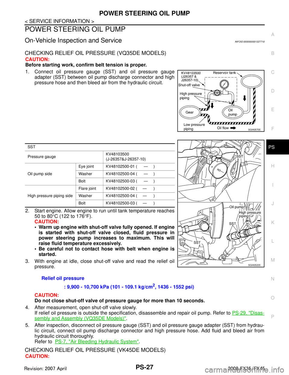
1. Connect oil pressure gauge (SST) and oil pressure gauge adapter (SST) between oil pump discharge connector and high
pressure hose and then bleed air from the hydraulic circuit.
2. Start engine. Allow engine to run until tank temperature reaches 50 to 80 °C (122 to 176 °F).
CAUTION:
Warm up engine with shut-o ff valve fully opened. If engine
is started with shut-off val ve closed, fluid pressure in
power steering pump increases to maximum. This will
raise fluid temperature excessively.
Be careful not to contact hose with belt when engine is
started.
3. With engine at idle, close shut-off valve and read the relief oil pressure.
CAUTION:
Do not close shut-off valve of pressu re gauge for more than 10 seconds.
4. After measurement, open shut-off valve slowly. If relief oil pressure is outside the specificat ion, disassemble and repair oil pump. Refer to PS-29, "
Disas-
sembly and Assembly (VQ35DE Models)".
5. After inspection, disconnect oil pressure gauge ( SST) and oil pressure gauge adapter (SST) from hydrau-
lic circuit, connect oil pump discharge connector and high pressure hose. Add fluid and bleed air from
hydraulic circuit thoroughly.
Refer to PS-7, "
Air Bleeding Hydraulic System".
CHECKING RELIEF OIL PRES SURE (VK45DE MODELS)
CAUTION:
SGIA0570E
SST
Pressure gauge KV48103500
(J-26357&J-26357-10)
Oil pump side Eye joint KV48102500-01 ( — )
Washer KV48102500-04 ( — )
Bolt KV48102500-03 ( — )
High pressure piping side Flare joint KV48102500-02 ( — )
Washer KV48102500-04 ( — )
Bolt KV48102500-03 ( — )
Relief oil pressure
: 9,900 - 10,700 kPa (101 - 109.1 kg/cm
2, 1436 - 1552 psi)
SGIA0522E
3AA93ABC3ACD3AC03ACA3AC03AC63AC53A913A773A893A873A873A8E3A773A983AC73AC93AC03AC3
3A893A873A873A8F3A773A9D3AAF3A8A3A8C3A863A9D3AAF3A8B3A8C
Page 3483 of 3924
PS-28
< SERVICE INFORMATION >
POWER STEERING OIL PUMP
Before starting work, confirm belt tension is proper.
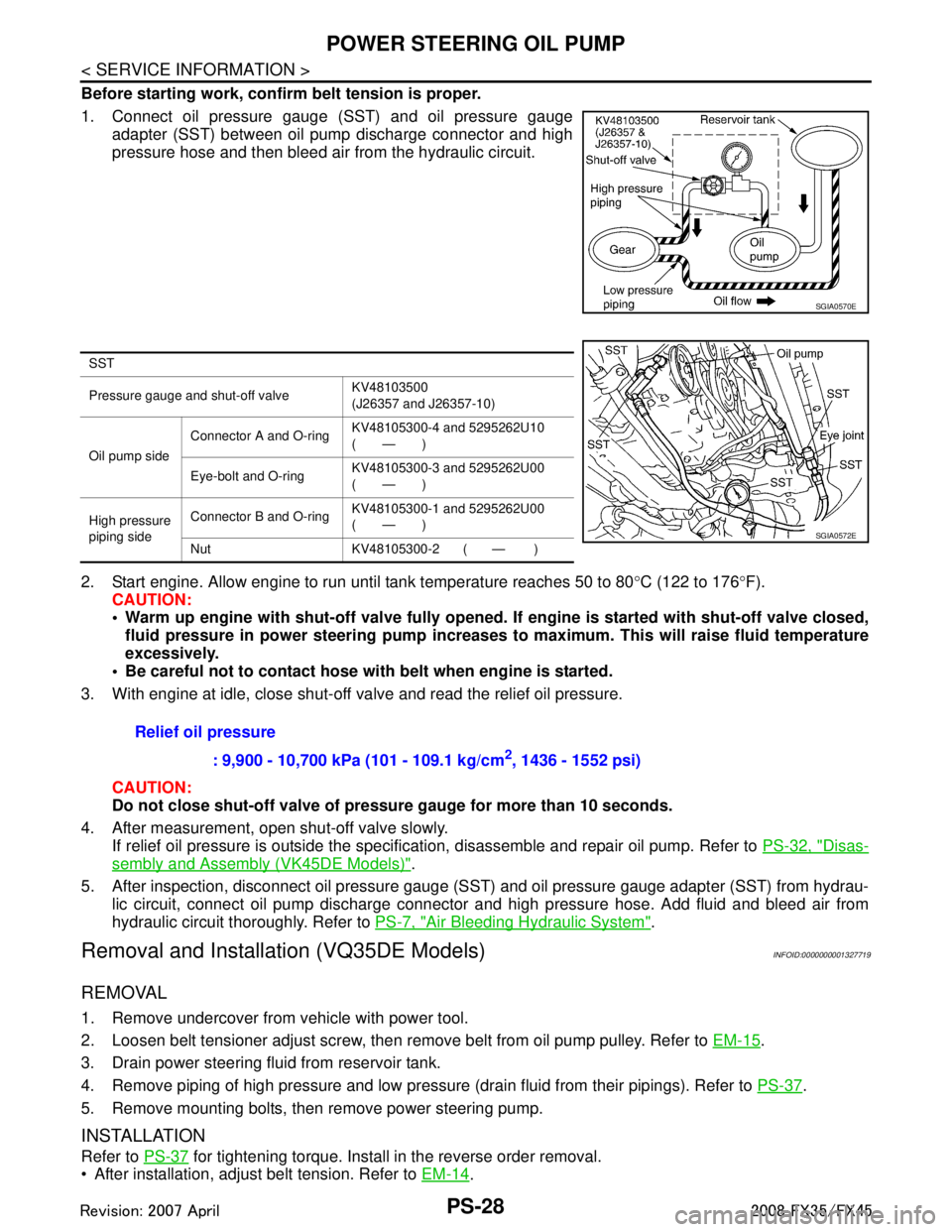
1. Connect oil pressure gauge (SST) and oil pressure gaugeadapter (SST) between oil pump discharge connector and high
pressure hose and then bleed air from the hydraulic circuit.
2. Start engine. Allow engine to run until tank temperature reaches 50 to 80 °C (122 to 176 °F).
CAUTION:
Warm up engine with shut-off val ve fully opened. If engine is started with shut-off valve closed,
fluid pressure in power steering pump increases to maximum. This will raise fluid temperature
excessively.
Be careful not to contact hose with belt when engine is started.
3. With engine at idle, close shut-off valve and read the relief oil pressure.
CAUTION:
Do not close shut-off valve of pressu re gauge for more than 10 seconds.
4. After measurement, open shut-off valve slowly. If relief oil pressure is outside the specification, disassemble and repair oil pump. Refer to PS-32, "
Disas-
sembly and Assembly (VK45DE Models)".
5. After inspection, disconnect oil pressure gauge (S ST) and oil pressure gauge adapter (SST) from hydrau-
lic circuit, connect oil pump discharge connector and high pressure hose. Add fluid and bleed air from
hydraulic circuit thoroughly. Refer to PS-7, "
Air Bleeding Hydraulic System".
Removal and Installation (VQ35DE Models)INFOID:0000000001327719
REMOVAL
1. Remove undercover from vehicle with power tool.
2. Loosen belt tensioner adjust screw, then remove belt from oil pump pulley. Refer to EM-15
.
3. Drain power steering fluid from reservoir tank.
4. Remove piping of high pressure and low pressure (drain fluid from their pipings). Refer to PS-37
.
5. Remove mounting bolts, then remove power steering pump.
INSTALLATION
Refer to PS-37 for tightening torque. Install in the reverse order removal.
After installation, adjust belt tension. Refer to EM-14
.
SGIA0570E
SST
Pressure gauge and shut-off valveKV48103500
(J26357 and J26357-10)
Oil pump side Connector A and O-ring
KV48105300-4 and 5295262U10
(—)
Eye-bolt and O-ring KV48105300-3 and 5295262U00
(—)
High pressure
piping side Connector B and O-ring
KV48105300-1 and 5295262U00
(—)
Nut KV48105300-2 ( — )
SGIA0572E
Relief oil pressure : 9,900 - 10,700 kPa (101 - 109.1 kg/cm
2, 1436 - 1552 psi)
3AA93ABC3ACD3AC03ACA3AC03AC63AC53A913A773A893A873A873A8E3A773A983AC73AC93AC03AC3
3A893A873A873A8F3A773A9D3AAF3A8A3A8C3A863A9D3AAF3A8B3A8C
Page 3487 of 3924
PS-32
< SERVICE INFORMATION >
POWER STEERING OIL PUMP
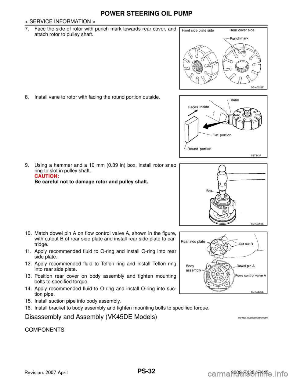
7. Face the side of rotor with punch mark towards rear cover, andattach rotor to pulley shaft.
8. Install vane to rotor with facing the round portion outside.
9. Using a hammer and a 10 mm (0.39 in) box, install rotor snap ring to slot in pulley shaft.
CAUTION:
Be careful not to damage rotor and pulley shaft.
10. Match dowel pin A on flow control valve A, shown in the figure, with cutout B of rear side plate and install rear side plate to car-
tridge.
11. Apply recommended fluid to O-ring and install O-ring into rear side plate.
12. Apply recommended fluid to Teflon ring and Install Teflon ring into rear side plate.
13. Position rear cover on body assembly and tighten mounting bolts to specified torque.
14. Apply recommended fluid to O-ring and install O-ring into suc- tion pipe.
15. Install suction pipe into body assembly.
16. Install bracket to body assembly and tighten mounting bolts to specified torque.
Disassembly and Assemb ly (VK45DE Models)INFOID:0000000001327722
COMPONENTS
SGIA0529E
SST843A
SGIA0063E
SGIA0530E
3AA93ABC3ACD3AC03ACA3AC03AC63AC53A913A773A893A873A873A8E3A773A983AC73AC93AC03AC3
3A893A873A873A8F3A773A9D3AAF3A8A3A8C3A863A9D3AAF3A8B3A8C
Page 3553 of 3924
FRONT OIL SEALRFD-11
< SERVICE INFORMATION >
CEF
G H
I
J
K L
M A
B
RFD
N
O P
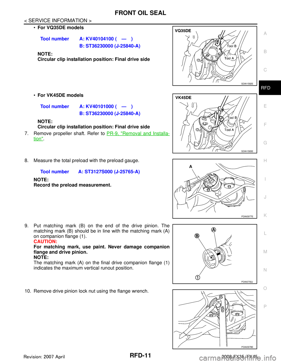
For VQ35DE models
NOTE:
Circular clip installation position: Final drive side
For VK45DE models
NOTE:
Circular clip installation position: Final drive side
7. Remove propeller shaft. Refer to PR-9, "
Removal and Installa-
tion".
8. Measure the total preload with the preload gauge. NOTE:
Record the preload measurement.
9. Put matching mark (B) on the end of the drive pinion. The matching mark (B) should be in line with the matching mark (A)
on companion flange (1).
CAUTION:
For matching mark, use pain t. Never damage companion
flange and drive pinion.
NOTE:
The matching mark (A) on the final drive companion flange (1)
indicates the maximum vertical runout position.
10. Remove drive pinion lock nut using the flange wrench. Tool number A: KV40104100 ( — )
B: ST36230000 (J-25840-A)
SDIA1582E
Tool number A: KV40101000 ( — )B: ST36230000 (J-25840-A)
SDIA1583E
Tool number A: ST3127S000 (J-25765-A)
PDIA0977E
PDIA0750J
PDIA0978E
3AA93ABC3ACD3AC03ACA3AC03AC63AC53A913A773A893A873A873A8E3A773A983AC73AC93AC03AC3
3A893A873A873A8F3A773A9D3AAF3A8A3A8C3A863A9D3AAF3A8B3A8C
Page 3679 of 3924

SE-40
< SERVICE INFORMATION >
AUTOMATIC DRIVE POSITIONER
Check continuity between the automatic drive positioner control unit
connector M50 terminal 40, 48 and ground.
OK or NG
OK >> Driver seat control unit circuit is OK.
NG >> Repair or replace harness between automatic drive
positioner control unit and ground.
CONSULT-III Function (AUTO DRIVE POS.)INFOID:0000000001328108
*1: For setting automatic drive positioner functions only.
*2: During vehicle driving, do not perform active test.
SELF-DIAGNOSIS RESULTS
Display Item List
40 (B) – Ground : Continuity should exist.
48 (B) – Ground : Continuity should exist.
PIIA5088E
CONSULT-III
diagnosis items Inspection item, self-diagnosis mode Content
Refer to
page
AUTO DRIVE
POSITIONER WORK SUPPORT*
1Changes the setting for each function.
SE-37
SELF–DIG RESULTS Check the self-diagnosis results. "SELF-DI-
AGNOSIS
RESULTS"
DATA MONITOR Selection from menu Displays the input data to driver seat control unit and
automatic driving positioned control unit on real-time
basis. "DATA
MONITOR"
CAN DIAGNOSTIC SUPPORT MONITOR The results of transmit / receive diagnosis of CAN
communication can be read LAN-39
ACTIVE TEST*2Gives a drive signal to a load to check the operation.
"ACTIVE
TEST"
DRIVER SEAT CONTROL UNIT PART NUM-
BER Displays driver seat control unit part No. —
BCM DATA MONITOR Selection from menu Displays the input data to BCM on real-time basisBL-36
DTCSelf-diagnosis item
(CONSULT-III indica- tion) DTC detection condition
Reference
page
U1000 CAN COMM CIRCUIT When driver seat control unit is not transmitting or receiving CAN communication
signal for 2 seconds or more.
SE-42
B2112 SEAT SLIDEWhen any manual and automatic operations are not performed, if any motor
operations of seat slide is detected for 0.1 second or more, status is judged
“Output error”. SE-44SE-53
B2113 SEAT RECLINING
When any manual and automatic operations are not performed, if any motor
operations of seat reclining is detected for 0.1 second or more, status is judged
“Output error”. SE-45SE-54
B2114 SEAT LIFTER FR
When any manual and automatic operations are not performed, if any motor
operations of seat lifting FR is detected for 0.1 second or more, status is judged
“Output error”. SE-46SE-55
B2115 SEAT LIFTER RR
When any manual and automatic operations are not performed, if any motor
operations of seat lifting RR is detected for 0.1 second or more, status is judged
“Output error”. SE-47SE-56
3AA93ABC3ACD3AC03ACA3AC03AC63AC53A913A773A893A873A873A8E3A773A983AC73AC93AC03AC3
3A893A873A873A8F3A773A9D3AAF3A8A3A8C3A863A9D3AAF3A8B3A8C
Page 3759 of 3924

SRS-22
< SERVICE INFORMATION >
TROUBLE DIAGNOSIS
Diagnosis results previously stored in the memory are displayed on the CONSULT-III screen. The stored
results are not erased until memory erasing is executed.
“TROUBLE DIAG RECORD”
With TROUBLE DIAG RECORD, diagnosis results previ ously erased by a reset operation can be displayed
on the CONSULT-III screen.
“ECU DISCRIMINATED NO.”
The diagnosis sensor unit for each vehicle model is assigned with its own, individual classification number.
This number will be displayed on the CONSULT-III scr een, as shown. When replacing the diagnosis sensor
unit, refer to the part number for the compatibility. Af ter installation, replacement with a correct unit can be
checked by confirming this classification number on the CONSULT-III screen.
After repair, make sure the discriminated number of diagnosis sensor unit installed to vehicle are same.
Refer to SRS-44, "
Removal and Installation".
HOW TO CHANGE SELF-DIAGNOSIS MODE WITH CONSULT-III
From User Mode to Diagnosis Mode
After selecting “AIR BAG” on the “SELECT SYSTEM” screen, User mode automatically changes to Diagnosis
mode.
From Diagnosis Mode to User Mode
To return to User mode from Diagnosis mode, touch “BACK” key of CONSULT-III until “SELECT SYSTEM”
appears, then diagnosis mode automat ically changes to User mode.
HOW TO ERASE SELF-DIAGNOSTIC RESULTS
“SELF-DIAG [CURRENT]”
A current self-diagnostic result is displayed on the CONSULT-III screen in real time.
After the malfunction is repaired completely, no malfunction is detected on “SELF-DIAG [CURRENT]”.
“SELF-DIAG [PAST]” Return to the “SELF-DIAG [CURRENT]” CONSULT-III screen by touching “BACK” key of CONSULT-III and
select “SELF-DIAG [CURRENT]” in SELECT DIAG MODE. Touch “ERASE” in “SELF-DIAG [CURRENT]”
mode.
NOTE:
If the memory of the malfunction in “SELF-DIAG [P AST]” is not erased, the User mode shows the system
malfunction by the operation of the warning lamp even if the malfunction is repaired completely.
“TROUBLE DIAG RECORD”
The memory of “TROUBLE DI AG RECORD” cannot be erased.
Self-Diagnosis Function (Without CONSULT-III)INFOID:0000000001524166
The reading of these results is accomplished “User mode” and “Diagnosis mode”.
After a malfunction is repaired, turn ignition switch ON. Diagnosis mode returns to the User mode. At that
time, the self-diagnostic result is cleared.
HOW TO CHANGE SELF-DIAGNOSIS MODE WITHOUT CONSULT-III
PHIA0709E
3AA93ABC3ACD3AC03ACA3AC03AC63AC53A913A773A893A873A873A8E3A773A983AC73AC93AC03AC3
3A893A873A873A8F3A773A9D3AAF3A8A3A8C3A863A9D3AAF3A8B3A8C
Page 3760 of 3924
TROUBLE DIAGNOSISSRS-23
< SERVICE INFORMATION >
C
DE
F
G
I
J
K L
M A
B
SRS
N
O P
HOW TO ERASE SELF-DIAGNOSIS RESULTS
After a malfunction is repaired, turn ignition swit ch OFF for at least one second, then back ON. Diagnosis
mode returns to the User mode. At that time, the self-diagnostic result is cleared.
SRS Operation CheckINFOID:0000000001524167
DIAGNOSTIC PROCEDURE
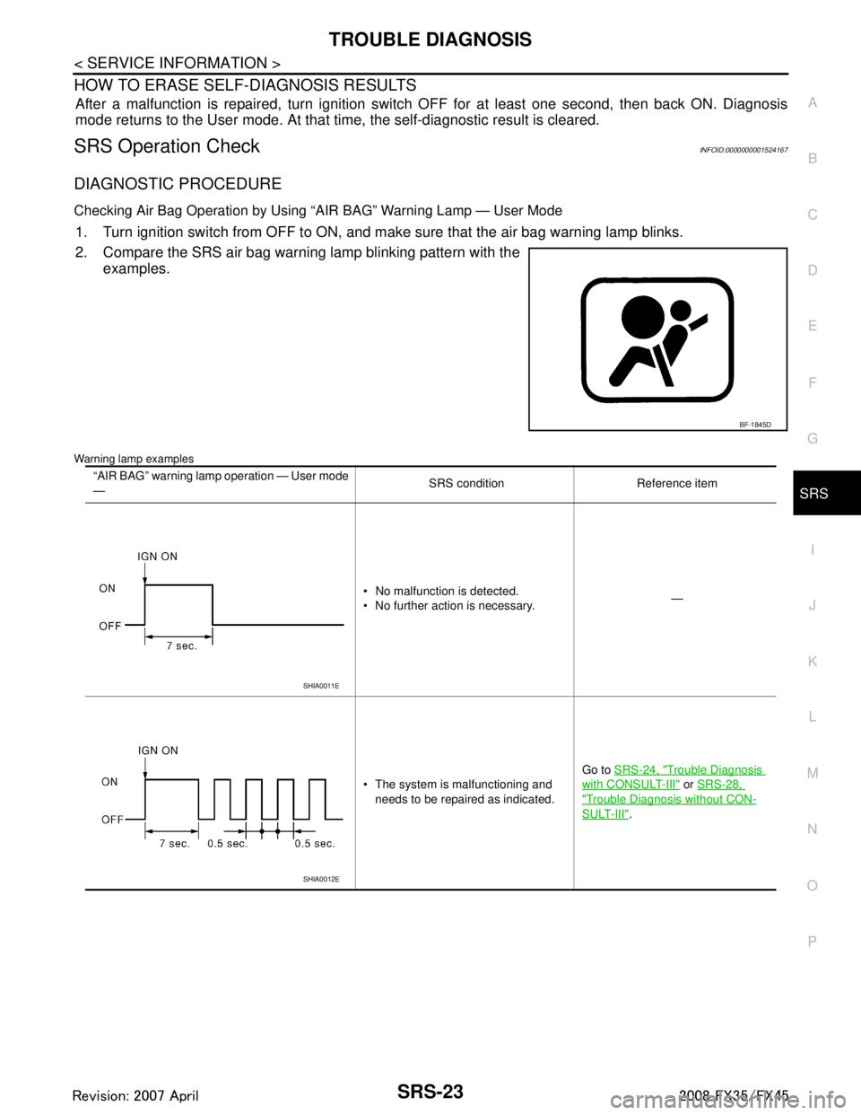
Checking Air Bag Operation by Using “AIR BAG” Warning Lamp — User Mode
1. Turn ignition switch from OFF to ON, and make sure that the air bag warning lamp blinks.
2. Compare the SRS air bag warning lamp blinking pattern with the
examples.
Warning lamp examples
BF-1845D
“AIR BAG” warning lamp operation — User mode
— SRS condition Reference item
No malfunction is detected.
No further action is necessary. —
The system is malfunctioning and needs to be repaired as indicated. Go to
SRS-24, "
Trouble Diagnosis
with CONSULT-III" or SRS-28,
"Trouble Diagnosis without CON-
SULT-III".
SHIA0011E
SHIA0012E
3AA93ABC3ACD3AC03ACA3AC03AC63AC53A913A773A893A873A873A8E3A773A983AC73AC93AC03AC3
3A893A873A873A8F3A773A9D3AAF3A8A3A8C3A863A9D3AAF3A8B3A8C
Page 3761 of 3924
![INFINITI FX35 2008 Service Manual
SRS-24
< SERVICE INFORMATION >
TROUBLE DIAGNOSIS
Trouble Diagnosis with CONSULT-III
INFOID:0000000001524168
DIAGNOSTIC PROCEDURE
DTC No. Index (“SELF-DIAG [ CURRENT]” “SELF-DIAG [PAST]” or INFINITI FX35 2008 Service Manual
SRS-24
< SERVICE INFORMATION >
TROUBLE DIAGNOSIS
Trouble Diagnosis with CONSULT-III
INFOID:0000000001524168
DIAGNOSTIC PROCEDURE
DTC No. Index (“SELF-DIAG [ CURRENT]” “SELF-DIAG [PAST]” or](/img/42/57017/w960_57017-3760.png)
SRS-24
< SERVICE INFORMATION >
TROUBLE DIAGNOSIS
Trouble Diagnosis with CONSULT-III
INFOID:0000000001524168
DIAGNOSTIC PROCEDURE
DTC No. Index (“SELF-DIAG [ CURRENT]” “SELF-DIAG [PAST]” or TROUBLE DIAG RECORD)
Air bag is deployed.
Seat belt pre-tensioner is deployed. Go to
SRS-47, "For Frontal Colli-
sion" or SRS-48, "For Side Collision"
Diagnosis sensor unit is malfunction-
ing.
Air bag power supply circuit is mal-
functioning.
SRS air bag warning lamp circuit is malfunctioning. Go to
SRS-32, "
Trouble Diagnosis:
"AIR BAG" Warning Lamp Does Not
Turn OFF".
Diagnosis sensor unit is malfunction- ing.
Air bag warning lamp circuit is mal-
functioning. Go to
SRS-32, "
Trouble Diagnosis:
"AIR BAG" Warning Lamp Does Not
Turn ON".
“AIR BAG” warning lamp operation — User mode
—
SRS condition Reference item
SHIA0013E
SHIA0014E
Diagnostic mode Description
SELF-DIAG RESULT The self-d iagnosis result is Displayed. (SELF-DIAG [ CURRENT], [PAST], [RECORD])
ECU DISCRIMINATED No. The parts number of diagnosis sensor units displayed.
Diagnostic item Explanation Repair order
“Recheck SRS at each replacement”
NO DTC IS DETECT-
ED. When malfunction is in-
dicated by the “AIR
BAG” warning lamp in
User mode. Low battery voltage (Less than 9V)
Self-diagnostic result “SELF-DIAG
[PAST]” (previously stored in the
memory) might not be erased after re-
pair.
Intermittent malfunction has been de- tected in the past. Go to
SRS-21, "
CONSULT-III Func-
tion".
No malfunction is detected. —
DIAGNOSIS SENSOR
UNIT (CONTROL UNIT)
[B1001-B1015] Diagnosis sensor is out of order. Replace diagnosis sensor unit.
(ACU)
3AA93ABC3ACD3AC03ACA3AC03AC63AC53A913A773A893A873A873A8E3A773A983AC73AC93AC03AC3
3A893A873A873A8F3A773A9D3AAF3A8A3A8C3A863A9D3AAF3A8B3A8C
Page 3766 of 3924
TROUBLE DIAGNOSISSRS-29
< SERVICE INFORMATION >
C
DE
F
G
I
J
K L
M A
B
SRS
N
O P
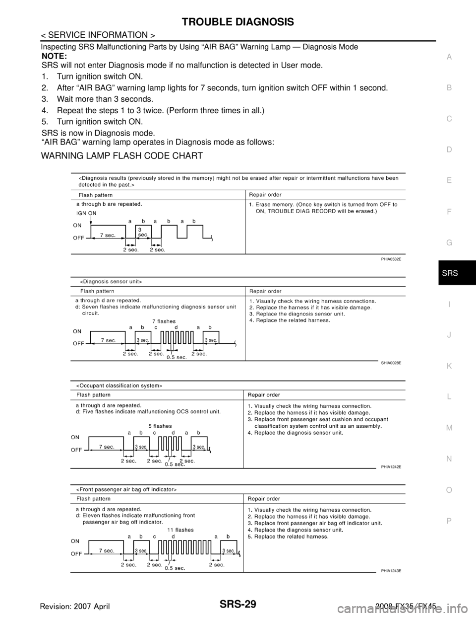
Inspecting SRS Malfunctioning Parts by Using “AIR BAG” Warning Lamp — Diagnosis Mode
NOTE:
SRS will not enter Diagnosis mode if no malfunction is detected in User mode.
1. Turn ignition switch ON.
2. After “AIR BAG” warning lamp lights for 7 seconds, turn ignition switch OFF within 1 second.
3. Wait more than 3 seconds.
4. Repeat the steps 1 to 3 twice. (Perform three times in all.)
5. Turn ignition switch ON.
SRS is now in Diagnosis mode.
“AIR BAG” warning lamp operates in Diagnosis mode as follows:
WARNING LAMP FLASH CODE CHART
PHIA0532E
SHIA0028E
PHIA1242E
PHIA1243E
3AA93ABC3ACD3AC03ACA3AC03AC63AC53A913A773A893A873A873A8E3A773A983AC73AC93AC03AC3
3A893A873A873A8F3A773A9D3AAF3A8A3A8C3A863A9D3AAF3A8B3A8C
Page 3787 of 3924

TF-1
DRIVELINE/AXLE
CEF
G H
I
J
K L
M
SECTION TF
A
B
TF
N
O P
CONTENTS
TRANSFER
SERVICE INFORMATION .. ..........................3
DTC INDEX ..................................................... .....3
C1201-C1210, U1000 ......................................... ......3
PRECAUTIONS ...................................................4
Precaution for Supplemental Restraint System
(SRS) "AIR BAG" and "SEAT BELT PRE-TEN-
SIONER" ............................................................. ......
4
Precaution .................................................................4
Service Notice or Precaution .....................................5
PREPARATION ...................................................6
Special Service Tool ........................................... ......6
Commercial Service Tool ..........................................7
NOISE, VIBRATION AND HARSHNESS
(NVH) TROUBLESHOOTING .............................
9
NVH Troubleshooting Chart ................................ ......9
TRANSFER FLUID .............................................10
Replacement ....................................................... ....10
Inspection ................................................................10
AWD SYSTEM ................................................ ....11
Power Transfer Diagram ..................................... ....11
System Description .................................................11
Schematic ...............................................................13
CAN Communication ...............................................13
TROUBLE DIAGNOSIS .....................................14
Fail-Safe Function ............................................... ....14
How to Perform Trouble Diagnosis .........................14
Location of Electrical Parts ......................................15
Circuit Diagram .......................................................16
Wiring Diagram - AWD - ..........................................17
Trouble Diagnosis Chart by Symptom ....................20
AWD Control Unit Input/Output Signal Reference
Value ................................................................... ....
20
CONSULT-III Function (ALL MODE AWD/4WD) ....21
TROUBLE DIAGNOSIS FOR SYSTEM .............24
DTC C1201 CONTROLLER FAILURE ................ ....24
DTC C1203 ABS SYSTEM ......................................24
DTC C1204 4WD SOLENOID ............................. ....25
DTC C1205 4WD ACTUATOR RLY ........................27
DTC C1210 ENGINE SIGNAL 1 ..............................28
DTC U1000 CAN COMM CIRCUIT .........................28
Power Supply Circuit for AWD Control Unit .............28
TROUBLE DIAGNOSIS FOR SYMPTOMS ......30
AWD Warning Lamp Does Not Turn ON When the
Ignition Switch Is Turned to ON ...............................
30
AWD Warning Lamp Does Not Turn OFF Several
Seconds after Engine Started ..................................
30
Heavy Tight-Corner Braking Symptom Occurs
When the Vehicle Is Driven and the Steering
Wheel Is Turned Fully to Either Side after the En-
gine Is Started .........................................................
32
Vehicle Does Not Enter AWD Mode Even Though
AWD Warning Lamp Turned to OFF .......................
33
While Driving, AWD Warning Lamp Flashes Rap-
idly (When Flashing in Approx. 1 Minute and Then
Turning OFF) ....................................................... ....
33
While Driving, AWD Warning Lamp Flashes Slow-
ly (When Continuing to Flash until Turning Ignition
Switch OFF) .............................................................
33
AWD CONTROL UNIT ......................................35
Removal and Installation .........................................35
FRONT OIL SEAL .............................................36
Removal and Installation .........................................36
REAR OIL SEAL ...............................................37
Removal and Installation .........................................37
AIR BREATHER HOSE ....................................39
Removal and Installation .........................................39
TRANSFER ASSEMBLY ..................................40
Removal and Installation .........................................40
Disassembly and Assembly .....................................40
3AA93ABC3ACD3AC03ACA3AC03AC63AC53A913A773A893A873A873A8E3A773A983AC73AC93AC03AC3
3A893A873A873A8F3A773A9D3AAF3A8A3A8C3A863A9D3AAF3A8B3A8C