Shift INFINITI M35 2006 Factory Owners Manual
[x] Cancel search | Manufacturer: INFINITI, Model Year: 2006, Model line: M35, Model: INFINITI M35 2006Pages: 5621, PDF Size: 65.56 MB
Page 308 of 5621

A/T SHIFT LOCK SYSTEM
AT-229
D
E
F
G
H
I
J
K
L
MA
B
AT
Revision: 2006 January2006 M35/M45
A/T SHIFT LOCK SYSTEMPFP:34950
DescriptionNCS001QP
The mechanical key interlock mechanism also operates as a shift lock:
With the ignition switch turned to ON, the selector lever cannot be shifted from “P” position to any other posi-
tions unless the brake pedal is depressed.
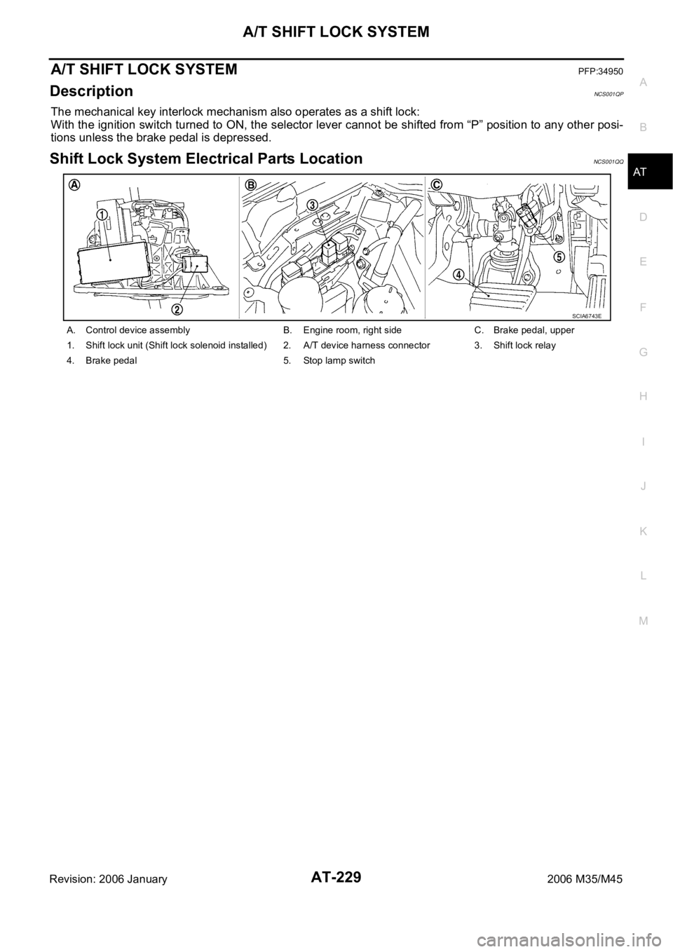
Shift Lock System Electrical Parts LocationNCS001QQ
A. Control device assembly B. Engine room, right side C. Brake pedal, upper
1. Shift lock unit (Shift lock solenoid installed) 2. A/T device harness connector 3. Shift lock relay
4. Brake pedal 5. Stop lamp switch
SCIA6743E
Page 309 of 5621

AT-230
A/T SHIFT LOCK SYSTEM
Revision: 2006 January2006 M35/M45
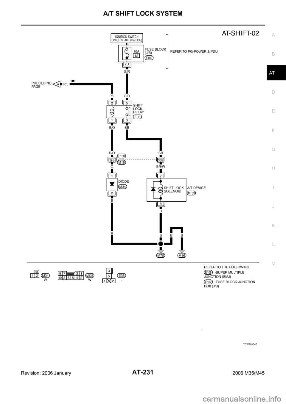
Wiring Diagram — AT — SHIFTNCS001QR
TCWT0353E
Page 310 of 5621

A/T SHIFT LOCK SYSTEM
AT-231
D
E
F
G
H
I
J
K
L
MA
B
AT
Revision: 2006 January2006 M35/M45
TCWT0354E
Page 311 of 5621

AT-232
A/T SHIFT LOCK SYSTEM
Revision: 2006 January2006 M35/M45
Diagnostic ProcedureNCS001QS
SYMPTOM:
Selector lever cannot be moved from “P” position with key in ON position and brake pedal
applied.
Selector lever can be moved from “P” position with key in ON position and brake pedal released.
1. CHECK SELECTOR LEVER POSITION
Check the selector lever position for damage. Refer to AT- 2 2 8 , "
Checking of A/T Position" .
OK or NG
OK >> GO TO 2.
NG >> Adjust control linkage. Refer to AT-227, "
Adjustment of A/T Position" .
2. CHECK POWER SOURCE
1. Turn ignition switch OFF.
2. Disconnect shift lock relay.
3. Check voltage between shift lock relay E35 terminal 2 and
ground.
OK or NG
OK >> GO TO 4.
NG >> GO TO 3.Vo l ta g e
Brake pedal depressed: Battery voltage
Brake pedal released: 0V
SCIA6866E
Page 312 of 5621

A/T SHIFT LOCK SYSTEM
AT-233
D
E
F
G
H
I
J
K
L
MA
B
AT
Revision: 2006 January2006 M35/M45
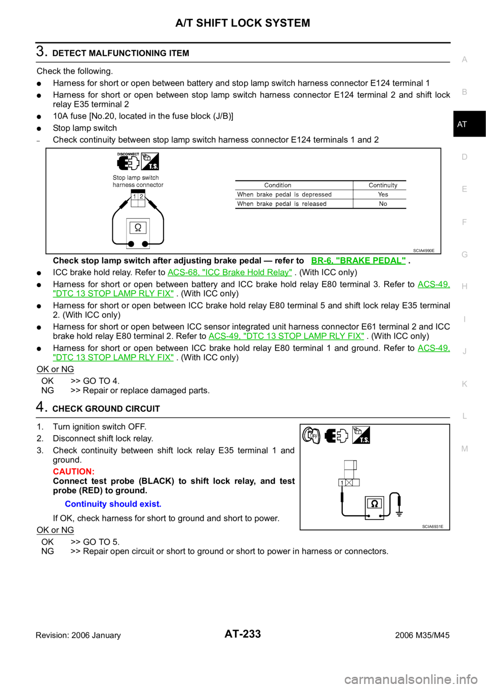
3. DETECT MALFUNCTIONING ITEM
Check the following.
Harness for short or open between battery and stop lamp switch harness connector E124 terminal 1
Harness for short or open between stop lamp switch harness connector E124 terminal 2 and shift lock
relay E35 terminal 2
10A fuse [No.20, located in the fuse block (J/B)]
Stop lamp switch
–Check continuity between stop lamp switch harness connector E124 terminals 1 and 2
Check stop lamp switch after adjusting brake pedal — refer to BR-6, "
BRAKE PEDAL" .
ICC brake hold relay. Refer to ACS-68, "ICC Brake Hold Relay" . (With ICC only)
Harness for short or open between battery and ICC brake hold relay E80 terminal 3. Refer to ACS-49,
"DTC 13 STOP LAMP RLY FIX" . (With ICC only)
Harness for short or open between ICC brake hold relay E80 terminal 5 and shift lock relay E35 terminal
2. (With ICC only)
Harness for short or open between ICC sensor integrated unit harness connector E61 terminal 2 and ICC
brake hold relay E80 terminal 2. Refer to ACS-49, "
DTC 13 STOP LAMP RLY FIX" . (With ICC only)
Harness for short or open between ICC brake hold relay E80 terminal 1 and ground. Refer to ACS-49,
"DTC 13 STOP LAMP RLY FIX" . (With ICC only)
OK or NG
OK >> GO TO 4.
NG >> Repair or replace damaged parts.
4. CHECK GROUND CIRCUIT
1. Turn ignition switch OFF.
2. Disconnect shift lock relay.
3. Check continuity between shift lock relay E35 terminal 1 and
ground.
CAUTION:
Connect test probe (BLACK) to shift lock relay, and test
probe (RED) to ground.
If OK, check harness for short to ground and short to power.
OK or NG
OK >> GO TO 5.
NG >> Repair open circuit or short to ground or short to power in harness or connectors.
SCIA4990E
Continuity should exist.
SCIA6931E
Page 313 of 5621

AT-234
A/T SHIFT LOCK SYSTEM
Revision: 2006 January2006 M35/M45
5. CHECK INPUT SIGNAL A/T DEVICE
1. Turn ignition switch OFF.
2. Disconnect A/T device harness connector.
3. Turn ignition switch ON. (Do not start engine.)
4. Check voltage between A/T device harness connector M133 ter-
minal 7 and ground.
OK or NG
OK >> GO TO 7.
NG >> GO TO 6.
6. DETECT MALFUNCTIONING ITEM
Check the following.
Harness for short or open between push-button ignition switch and shift lock relay E35 terminal 5
Harness for short or open between shift lock relay E35 terminal 3 and A/T device harness connector
M133 terminal 7
10A fuse [No.12, located in the fuse block (J/B)]
Push-button ignition switch (Refer to PG-3, "POWER SUPPLY ROUTING CIRCUIT" .)
Shift lock relay
–Check continuity between shift lock relay E35 terminal 3 and 5
OK or NG
OK >> GO TO 7.
NG >> Repair or replace damaged parts.
7. CHECK GROUND CIRCUIT
1. Turn ignition switch OFF.
2. Disconnect A/T device harness connector.
3. Check continuity between A/T device harness connector M133
terminal 8 and ground.
If OK, check harness for short to ground and short to power.
OK or NG
OK >> GO TO 8.
NG >> Repair open circuit or short to ground or short to power
in harness or connectors. Vo l ta g e
Brake pedal depressed: Battery voltage
Brake pedal released: 0V
SCIA6867E
Condition Continuity
12V direct current supply between terminal 1 and 2 Yes
OFF No
SCIA1245E
Continuity should exist.
SCIA6868E
Page 314 of 5621

A/T SHIFT LOCK SYSTEM
AT-235
D
E
F
G
H
I
J
K
L
MA
B
AT
Revision: 2006 January2006 M35/M45
8. CHECK SHIFT LOCK SOLENOID
1. Connect A/T device harness connector.
2. Turn ignition switch ON. (Do not start engine.)
3. Check shift lock solenoid operation.
OK or NG
OK >>INSPECTION END
NG >> Repair or replace damage parts.
Condition Brake pedal Operation
When ignition switch is turned to ON position and
selector lever is set in “P” position.Depressed Yes
Released No
Page 444 of 5621

SERVICE DATA AND SPECIFICATIONS (SDS)
AT-365
D
E
F
G
H
I
J
K
L
MA
B
AT
Revision: 2006 January2006 M35/M45
SERVICE DATA AND SPECIFICATIONS (SDS)PFP:00030
General SpecificationsNCS001RD
*1: Refer to MA-12, "Fluids and Lubricants" .
Vehicle Speed at Which Gear Shifting OccursNCS001RE
2WD MODELS
At half throttle, the accelerator opening is 4/8 of the full opening.
At half throttle, the accelerator opening is 4/8 of the full opening.
AWD MODELS
At half throttle, the accelerator opening is 4/8 of the full opening. Applied modelVQ35DE engine VK45DE engine
2WD AWD 2WD
Automatic transmission model RE5R05A
Transmission model code number 97X06, 98X1A 97X07, 98X0E 95X12, 95X7A
Stall torque ratio 1.72: 1 1.85: 1
Transmission gear ratio1st 3.842 3.827
2nd 2.353 2.368
3rd 1.529 1.520
4th 1.000 1.000
5th 0.839 0.834
Reverse 2.765 2.613
Recommended fluid Genuine NISSAN Matic J ATF*1
Fluid capacity 10.3 liter (10-7/8 US qt, 9-1/8 Imp qt)
CAUTION:
Use only Genuine NISSAN Matic J ATF. Do not mix with other fluid.
Using ATF other than Genuine NISSAN Matic J ATF will deteriorate in driveability and A/T durability, and may damage the
A/T, which is not covered by the warranty.
Engine model VQ35DE
Throttle positionVehicle speed km/h (MPH)
D
1 D2D2 D3D3 D4D4 D5D5 D4D4 D3D3 D2D2 D1
Full throttle 50 - 58
(31 - 36)85 - 93
(53 - 58)127 - 135
(79 - 84)196 - 204
(122 - 127)192 - 200
(119 - 124)114- 122
(71 - 76)70 - 78
(43 - 48)26 - 34
(16 - 21)
Half throttle 40 - 48
(25 - 30)69 - 77
(43 - 48)107 - 115
(66 - 71)139 - 147
(86 - 91)111 - 11 9
(69 - 74)67 - 75
(42 - 47)34 - 42
(21 - 26)19 - 27
(12 - 17)
Engine model VK45DE
Throttle positionVehicle speed km/h (MPH)
D
1 D2D2 D3D3 D4D4 D5D5 D4D4 D3D3 D2D2 D1
Full throttle 54 - 62
(34 - 39)89 - 97
(55 - 60)139 - 147
(86 - 91)207 - 215
(129 - 134)203 - 211
(126 - 131)122 - 130
(76 - 81)73 - 81
(45 - 50)28 - 36
(17 - 22)
Half throttle 46 - 54
(29 - 34)81 - 89
(50 - 55)126 - 134
(78 - 83)155 - 163
(96 - 101)128 - 136
(80 - 85)70 - 78
(43 - 48)28 - 36
(17 - 22)7 - 15
(4 - 9)
Engine model VQ35DE
Throttle positionVehicle speed km/h (MPH)
D
1 D2D2 D3D3 D4D4 D5D5 D4D4 D3D3 D2D2 D1
Full throttle 48 - 56
(30 - 35)81 - 89
(50 - 55)121 - 129
(75 - 80)188 - 196
(117 - 122)184 - 192
(114 - 119)109 - 117
(68 - 73)66 - 74
(41 - 46)25 - 33
(16 - 21)
Half throttle 38 - 46
(24 - 29)66 - 74
(41 - 46)102 - 110
(63 - 68)133 - 141
(83 - 88)106 - 114
(66 - 71)64 - 72
(40 - 45)32 - 40
(20 - 25)18 - 26
(11 - 16)
Page 482 of 5621

AIR CONDITIONER CONTROL
ATC-35
C
D
E
F
G
H
I
K
L
MA
B
AT C
Revision: 2006 January2006 M35/M45
A/C SWITCH
Compressor is ON or OFF with this switch.
(Pressing the A/C switch when the A/C switch is ON will turn OFF the A/C switch and compressor.)
FAN SWITCHES
The blower speed is manually controlled with this switch. Seven speeds are available for manual control (as
shown on the display screen).
OFF SWITCH
Compressor and blower are OFF, intake doors are set to the outside air position, and the mode doors are set
to the foot (19% vent, 58% foot and 23% defrost) position.
REAR WINDOW DEFOGGER SWITCH
When illumination is ON, rear window is defogged.
INTAKE SWITCH
When intake switch is ON, FRE LED turns ON, and air inlet is fixed to FRE.
When press intake switch again, REC LED turns ON, and air inlet is fixed to REC.
When intake switch is pressed for approximately 1.5 seconds or longer, FRE and REC LEDs blink twice.
Then, automatic control mode is entered. Inlet status is displayed by LED during automatic controlled.
When FRE LED is turned ON, shifting mode position to D/F or DEF, or when compressor is turned from
ON to OFF, intake switch is automatically turned OFF (fixed to FRE mode). REC mode can be re-entered
by pressing intake switch again, and then compressor is turned ON. (Except D/F or DEF position)
DUAL SWITCH
When the DUAL switch indicator is illuminated, the driver-side and passenger-side temperature can each
be set independently.
When the DUAL switch indicator is not illuminated, the driver-side outlet and setting temperature is
applied to both sides.
Control Operation (Rear Control Switch)NJS000G8
AUTO SWITCH
When pressing AUTO switch, display for turned on AUTO and fan speed is automatically controlled.
When pressing AUTO switch, air inlet, air outlet, fan speed, and discharge air temperature are automati-
cally controlled.
FA N S W I T C H
The blower speed is manually controlled with this switch. Five speeds are available for manual control (as
shown on the display screen).
REAR TEMPERATURE CONTROL SWITCH
Increases or decreases the set temperature.
RJIA4216E
Page 502 of 5621

TROUBLE DIAGNOSIS
ATC-55
C
D
E
F
G
H
I
K
L
MA
B
AT C
Revision: 2006 January2006 M35/M45
Self-diagnosis FunctionNJS000GJ
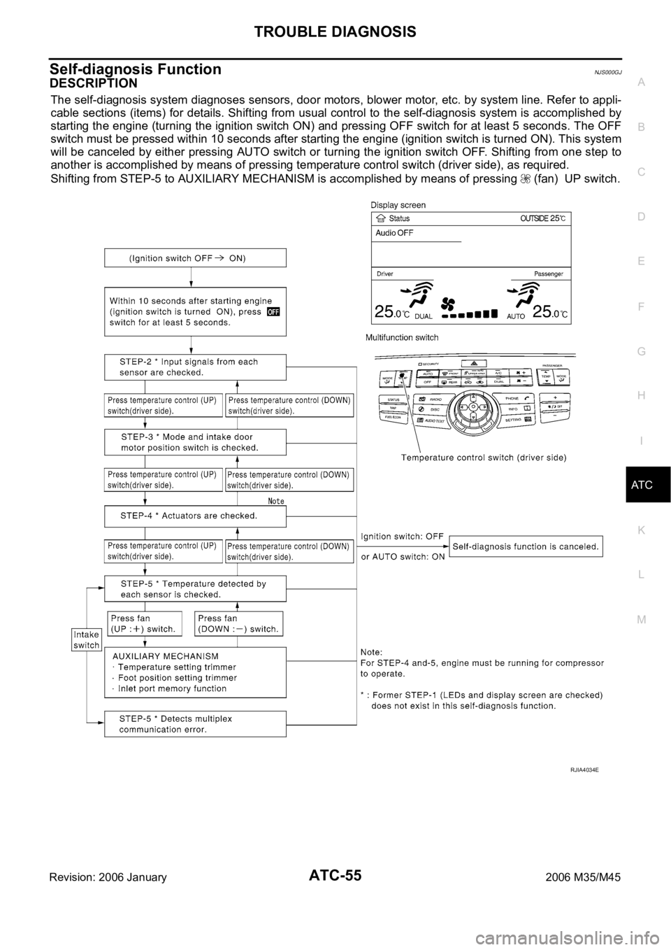
DESCRIPTION
The self-diagnosis system diagnoses sensors, door motors, blower motor, etc. by system line. Refer to appli-
cable sections (items) for details. Shifting from usual control to the self-diagnosis system is accomplished by
starting the engine (turning the ignition switch ON) and pressing OFF switch for at least 5 seconds. The OFF
switch must be pressed within 10 seconds after starting the engine (ignition switch is turned ON). This system
will be canceled by either pressing AUTO switch or turning the ignition switch OFF. Shifting from one step to
another is accomplished by means of pressing temperature control switch (driver side), as required.
Shifting from STEP-5 to AUXILIARY MECHANISM is accomplished by means of pressing (fan) UP switch.
RJIA4034E