Shift INFINITI M35 2006 Factory Manual Online
[x] Cancel search | Manufacturer: INFINITI, Model Year: 2006, Model line: M35, Model: INFINITI M35 2006Pages: 5621, PDF Size: 65.56 MB
Page 296 of 5621

TROUBLE DIAGNOSIS FOR SYMPTOMS
AT-217
D
E
F
G
H
I
J
K
L
MA
B
AT
Revision: 2006 January2006 M35/M45
A/T Does Not Shift: 3rd Gear 2nd GearNCS001QI
SYMPTOM:
When shifted from M3 to M2 position in manual mode, does not downshift from 3rd to 2nd gear.
DIAGNOSTIC PROCEDURE
1. CHECK SELF-DIAGNOSTIC RESULTS
Perform self-diagnosis. Refer to AT- 9 2 , "
SELF-DIAGNOSTIC RESULT MODE" , AT- 1 0 3 , "TCM SELF-DIAG-
NOSTIC PROCEDURE (NO TOOLS)" .
Is any malfunction detected by self-diagnostic results?
YES >> Check malfunctioning system. Refer to AT- 9 2 , "SELF-DIAGNOSTIC RESULT MODE" , AT- 1 0 4 ,
"Judgement Self-diagnosis Code" .
NO >> GO TO 2.
2. CHECK A/T FLUID LEVEL
Check A/T fluid level. Refer to AT- 1 3 , "
Checking A/T Fluid" .
OK or NG
OK >> GO TO 3.
NG >> Refill ATF.
3. CHECK CONTROL LINKAGE
Check control linkage.
Refer to AT-228, "Checking of A/T Position" .
OK or NG
OK >> GO TO 4.
NG >> Adjust control linkage. Refer to AT-227, "
Adjustment of A/T Position" .
4. CHECK MANUAL MODE SWITCH
Check manual mode switch. Refer to AT-167, "
DTC P1815 MANUAL MODE SWITCH" .
OK or NG
OK >> GO TO 5.
NG >> Repair or replace damaged parts.
5. CHECK A/T FLUID CONDITION
1. Remove oil pan. Refer to AT- 2 3 6 , "
Control Valve With TCM and A/T Fluid Temperature Sensor 2" .
2. Check A/T fluid condition. Refer to AT-53, "
A/T Fluid Condition Check" .
OK or NG
OK >> GO TO 6.
NG >> GO TO 9.
6. DETECT MALFUNCTIONING ITEM
Check malfunction items. If any items are damaged, repair or replace damaged parts. Refer to AT- 6 4 ,
"Symptom Chart" (Symptom No.49).
OK or NG
OK >> GO TO 7.
NG >> Repair or replace damaged parts.
Page 297 of 5621

AT-218
TROUBLE DIAGNOSIS FOR SYMPTOMS
Revision: 2006 January2006 M35/M45
7. CHECK SYMPTOM
Check again. Refer to AT- 6 2 , "
Cruise Test - Part 3" .
OK or NG
OK >>INSPECTION END
NG >> GO TO 8.
8. CHECK TCM
1. Check TCM input/output signals. Refer to AT- 8 9 , "
TCM Input/Output Signal Reference Values" .
2. If NG, recheck A/T assembly harness connector terminals for damage or loose connection with harness
connector.
OK or NG
OK >>INSPECTION END
NG >> Repair or replace damaged parts.
9. DETECT MALFUNCTIONING ITEM
Check malfunction items. If any items are damaged, repair or replace damaged parts. Refer to AT- 6 4 ,
"Symptom Chart" (Symptom No.49).
OK or NG
OK >> GO TO 7.
NG >> Repair or replace damaged parts.
A/T Does Not Shift: 2nd Gear 1st GearNCS001QJ
SYMPTOM:
When shifted from M2 to M1 position in manual mode, does not downshift from 2nd to 1st gear.
DIAGNOSTIC PROCEDURE
1. CHECK SELF-DIAGNOSTIC RESULTS
Perform self-diagnosis. Refer to AT- 9 2 , "
SELF-DIAGNOSTIC RESULT MODE" , AT- 1 0 3 , "TCM SELF-DIAG-
NOSTIC PROCEDURE (NO TOOLS)" .
Is any malfunction detected by self-diagnostic results?
YES >> Check malfunctioning system. Refer to AT- 9 2 , "SELF-DIAGNOSTIC RESULT MODE" , AT- 1 0 4 ,
"Judgement Self-diagnosis Code" .
NO >> GO TO 2.
2. CHECK A/T FLUID LEVEL
Check A/T fluid level. Refer to AT-13, "
Checking A/T Fluid" .
OK or NG
OK >> GO TO 3.
NG >> Refill ATF.
3. CHECK CONTROL LINKAGE
Check control linkage.
Refer to AT-228, "Checking of A/T Position" .
OK or NG
OK >> GO TO 4.
NG >> Adjust control linkage. Refer to AT-227, "
Adjustment of A/T Position" .
Page 299 of 5621
AT-220
TROUBLE DIAGNOSIS FOR SYMPTOMS
Revision: 2006 January2006 M35/M45
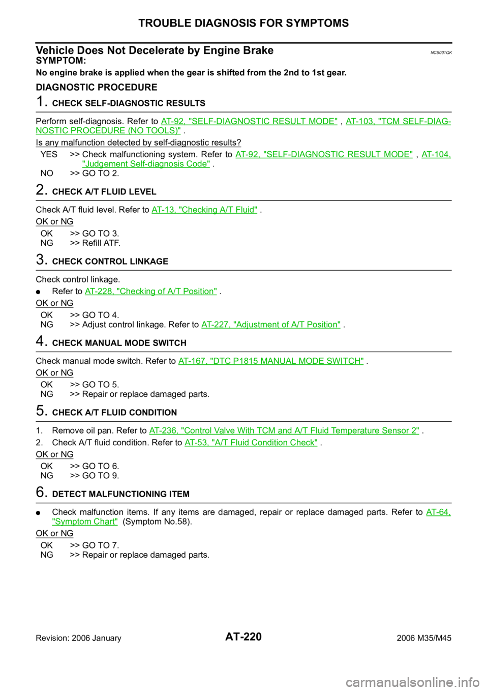
Vehicle Does Not Decelerate by Engine BrakeNCS001QK
SYMPTOM:
No engine brake is applied when the gear is shifted from the 2nd to 1st gear.
DIAGNOSTIC PROCEDURE
1. CHECK SELF-DIAGNOSTIC RESULTS
Perform self-diagnosis. Refer to AT- 9 2 , "
SELF-DIAGNOSTIC RESULT MODE" , AT- 1 0 3 , "TCM SELF-DIAG-
NOSTIC PROCEDURE (NO TOOLS)" .
Is any malfunction detected by self-diagnostic results?
YES >> Check malfunctioning system. Refer to AT- 9 2 , "SELF-DIAGNOSTIC RESULT MODE" , AT- 1 0 4 ,
"Judgement Self-diagnosis Code" .
NO >> GO TO 2.
2. CHECK A/T FLUID LEVEL
Check A/T fluid level. Refer to AT-13, "
Checking A/T Fluid" .
OK or NG
OK >> GO TO 3.
NG >> Refill ATF.
3. CHECK CONTROL LINKAGE
Check control linkage.
Refer to AT-228, "Checking of A/T Position" .
OK or NG
OK >> GO TO 4.
NG >> Adjust control linkage. Refer to AT-227, "
Adjustment of A/T Position" .
4. CHECK MANUAL MODE SWITCH
Check manual mode switch. Refer to AT-167, "
DTC P1815 MANUAL MODE SWITCH" .
OK or NG
OK >> GO TO 5.
NG >> Repair or replace damaged parts.
5. CHECK A/T FLUID CONDITION
1. Remove oil pan. Refer to AT-236, "
Control Valve With TCM and A/T Fluid Temperature Sensor 2" .
2. Check A/T fluid condition. Refer to AT- 5 3 , "
A/T Fluid Condition Check" .
OK or NG
OK >> GO TO 6.
NG >> GO TO 9.
6. DETECT MALFUNCTIONING ITEM
Check malfunction items. If any items are damaged, repair or replace damaged parts. Refer to AT- 6 4 ,
"Symptom Chart" (Symptom No.58).
OK or NG
OK >> GO TO 7.
NG >> Repair or replace damaged parts.
Page 301 of 5621

AT-222
SHIFT CONTROL SYSTEM
Revision: 2006 January2006 M35/M45
SHIFT CONTROL SYSTEMPFP:34901
Control Device Removal and InstallationNCS001QL
CONTROL DEVICE COMPONENTS (2WD MODELS)
1. Selector lever knob 2. Lock pin 3. Control device assembly
4. Snap pin 5. Plain washer 6. Color
7. Plain washer 8. Pivot pin 9. Control rod
10. Insulator 11. Dust cover plate 12. Dust cover
Refer to GI section to make sure icons (symbol marks) in the figure. Refer to GI-11, "
Components" .
SCIA6755E
Page 302 of 5621
SHIFT CONTROL SYSTEM
AT-223
D
E
F
G
H
I
J
K
L
MA
B
AT
Revision: 2006 January2006 M35/M45
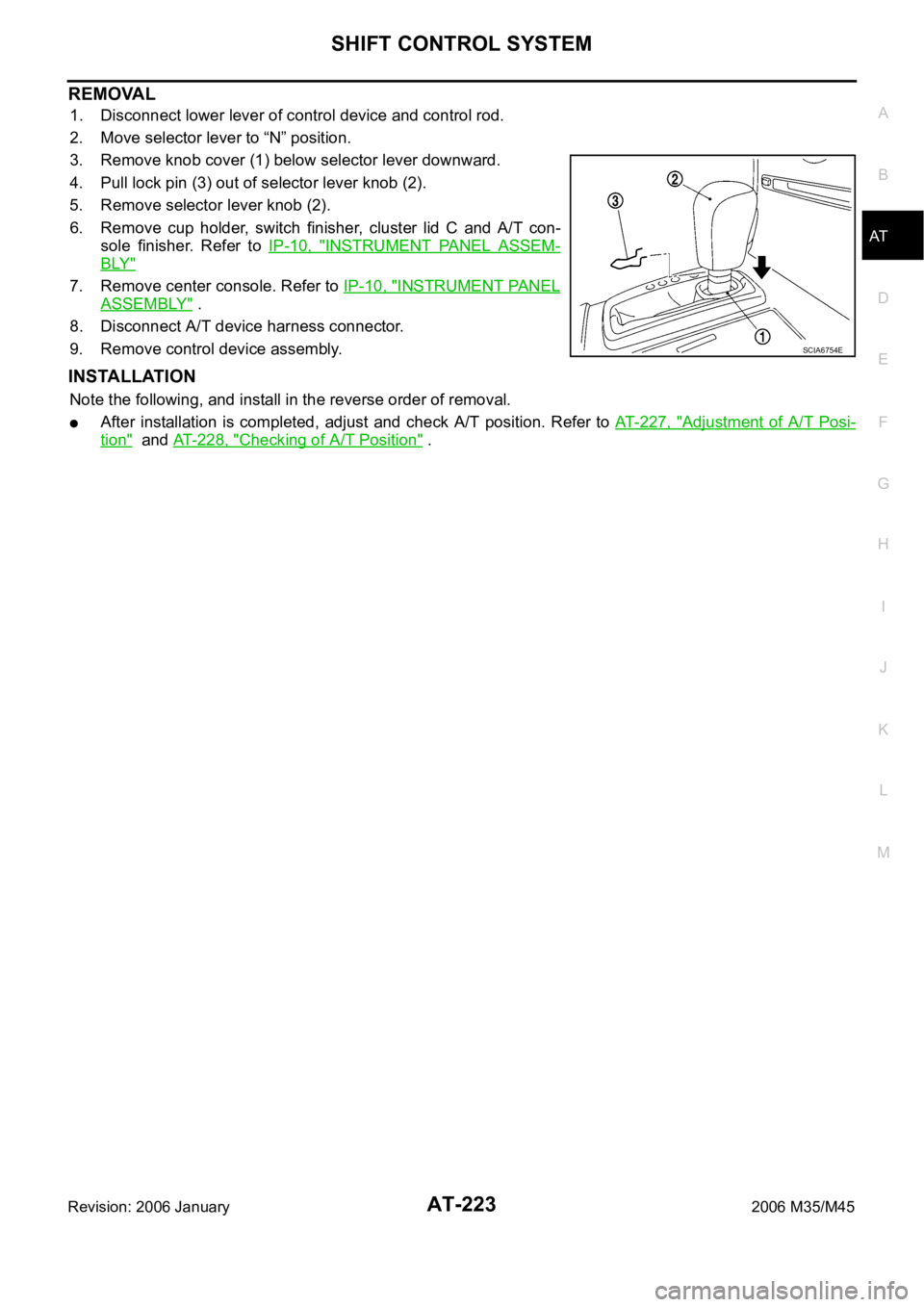
REMOVAL
1. Disconnect lower lever of control device and control rod.
2. Move selector lever to “N” position.
3. Remove knob cover (1) below selector lever downward.
4. Pull lock pin (3) out of selector lever knob (2).
5. Remove selector lever knob (2).
6. Remove cup holder, switch finisher, cluster lid C and A/T con-
sole finisher. Refer to IP-10, "
INSTRUMENT PANEL ASSEM-
BLY"
7. Remove center console. Refer to IP-10, "INSTRUMENT PANEL
ASSEMBLY" .
8. Disconnect A/T device harness connector.
9. Remove control device assembly.
INSTALLATION
Note the following, and install in the reverse order of removal.
After installation is completed, adjust and check A/T position. Refer to AT- 2 2 7 , "Adjustment of A/T Posi-
tion" and AT-228, "Checking of A/T Position" .
SCIA6754E
Page 303 of 5621
AT-224
SHIFT CONTROL SYSTEM
Revision: 2006 January2006 M35/M45
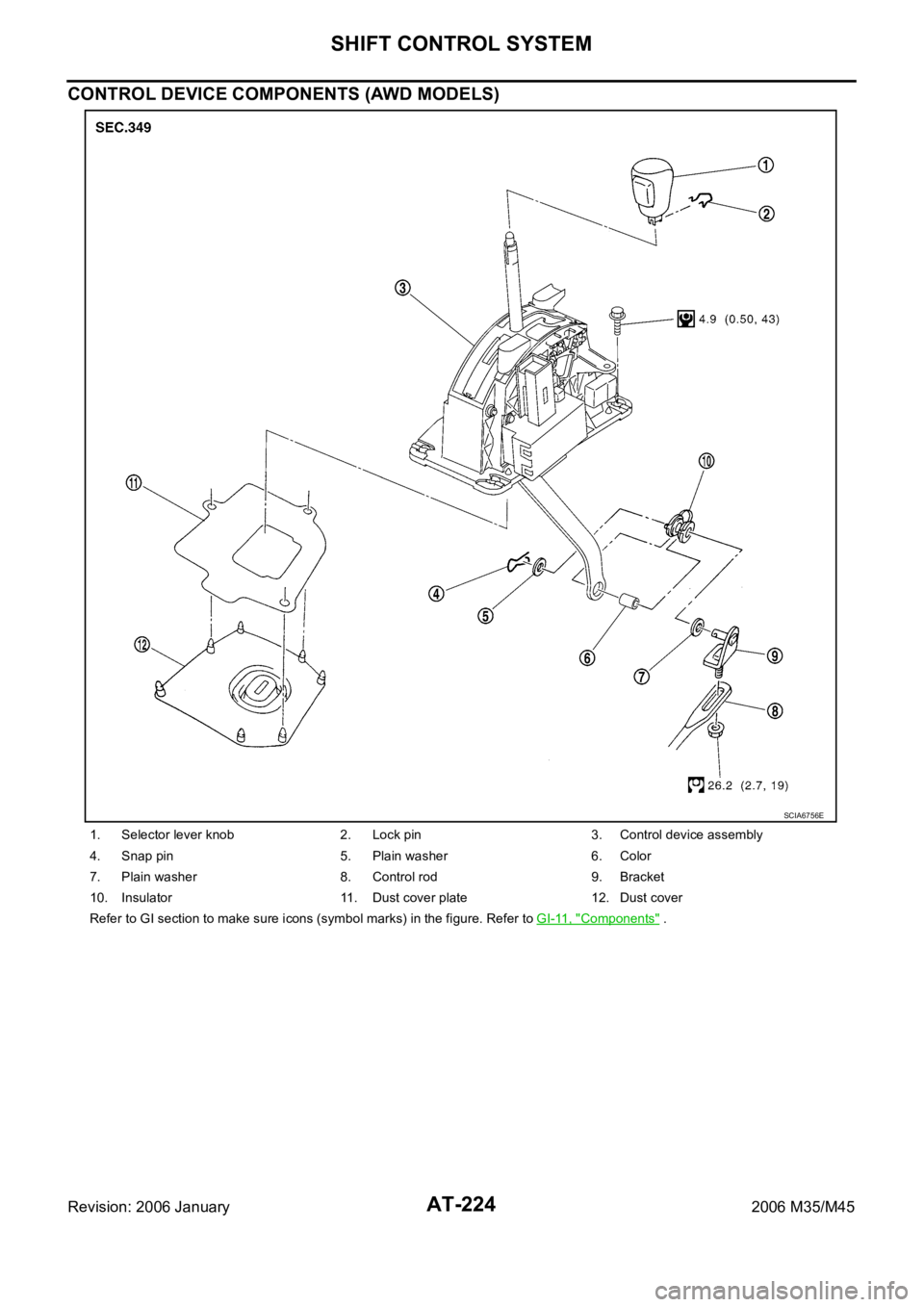
CONTROL DEVICE COMPONENTS (AWD MODELS)
1. Selector lever knob 2. Lock pin 3. Control device assembly
4. Snap pin 5. Plain washer 6. Color
7. Plain washer 8. Control rod 9. Bracket
10. Insulator 11. Dust cover plate 12. Dust cover
Refer to GI section to make sure icons (symbol marks) in the figure. Refer to GI-11, "
Components" .
SCIA6756E
Page 304 of 5621
SHIFT CONTROL SYSTEM
AT-225
D
E
F
G
H
I
J
K
L
MA
B
AT
Revision: 2006 January2006 M35/M45
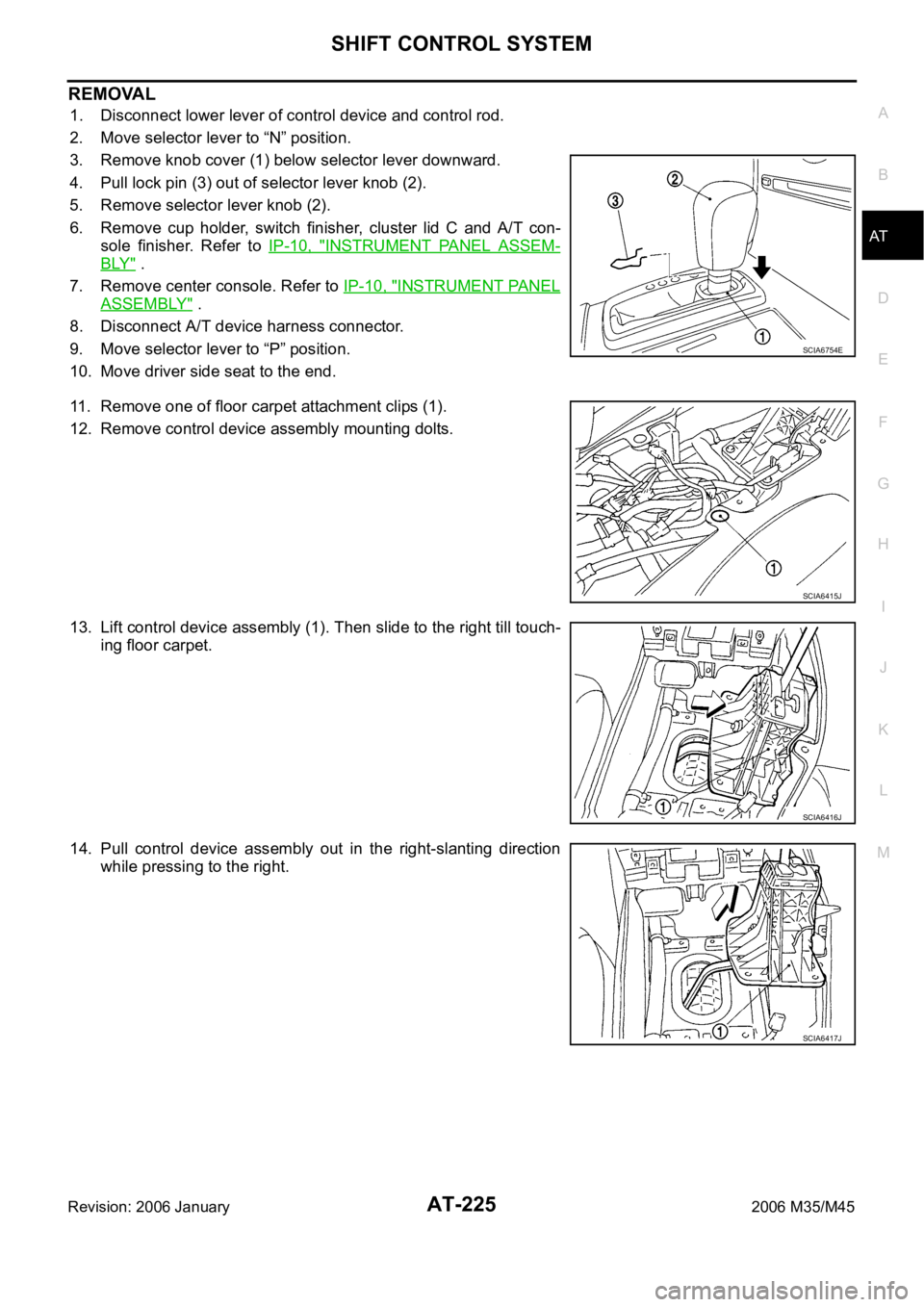
REMOVAL
1. Disconnect lower lever of control device and control rod.
2. Move selector lever to “N” position.
3. Remove knob cover (1) below selector lever downward.
4. Pull lock pin (3) out of selector lever knob (2).
5. Remove selector lever knob (2).
6. Remove cup holder, switch finisher, cluster lid C and A/T con-
sole finisher. Refer to IP-10, "
INSTRUMENT PANEL ASSEM-
BLY" .
7. Remove center console. Refer to IP-10, "
INSTRUMENT PANEL
ASSEMBLY" .
8. Disconnect A/T device harness connector.
9. Move selector lever to “P” position.
10. Move driver side seat to the end.
11. Remove one of floor carpet attachment clips (1).
12. Remove control device assembly mounting dolts.
13. Lift control device assembly (1). Then slide to the right till touch-
ing floor carpet.
14. Pull control device assembly out in the right-slanting direction
while pressing to the right.
SCIA6754E
SCIA6415J
SCIA6416J
SCIA6417J
Page 305 of 5621

AT-226
SHIFT CONTROL SYSTEM
Revision: 2006 January2006 M35/M45
INSTALLATION
Note the following, and install in the reverse order of removal.
NOTE:
Bend control device assembly (1) to vehicle, then insert lower lever
(2) to the rear of vehicle.
After installation is completed, adjust and check A/T position.
Refer to AT- 2 2 7 , "
Adjustment of A/T Position" and AT- 2 2 8 ,
"Checking of A/T Position" .
Control Rod Removal and InstallationNCS001QM
CONTROL ROD COMPONENTS (2WD MODELS)
Refer to the figure below for control rod removal and installation procedure.
SCIA6418J
1. Control device assembly 2. A/T assembly 3. Manual lever
4. Control rod 5. Lower lever
Refer to GI section to make sure icons (symbol marks) in the figure. Refer to GI-11, "
Components" .
SCIA6504J
Page 306 of 5621
SHIFT CONTROL SYSTEM
AT-227
D
E
F
G
H
I
J
K
L
MA
B
AT
Revision: 2006 January2006 M35/M45
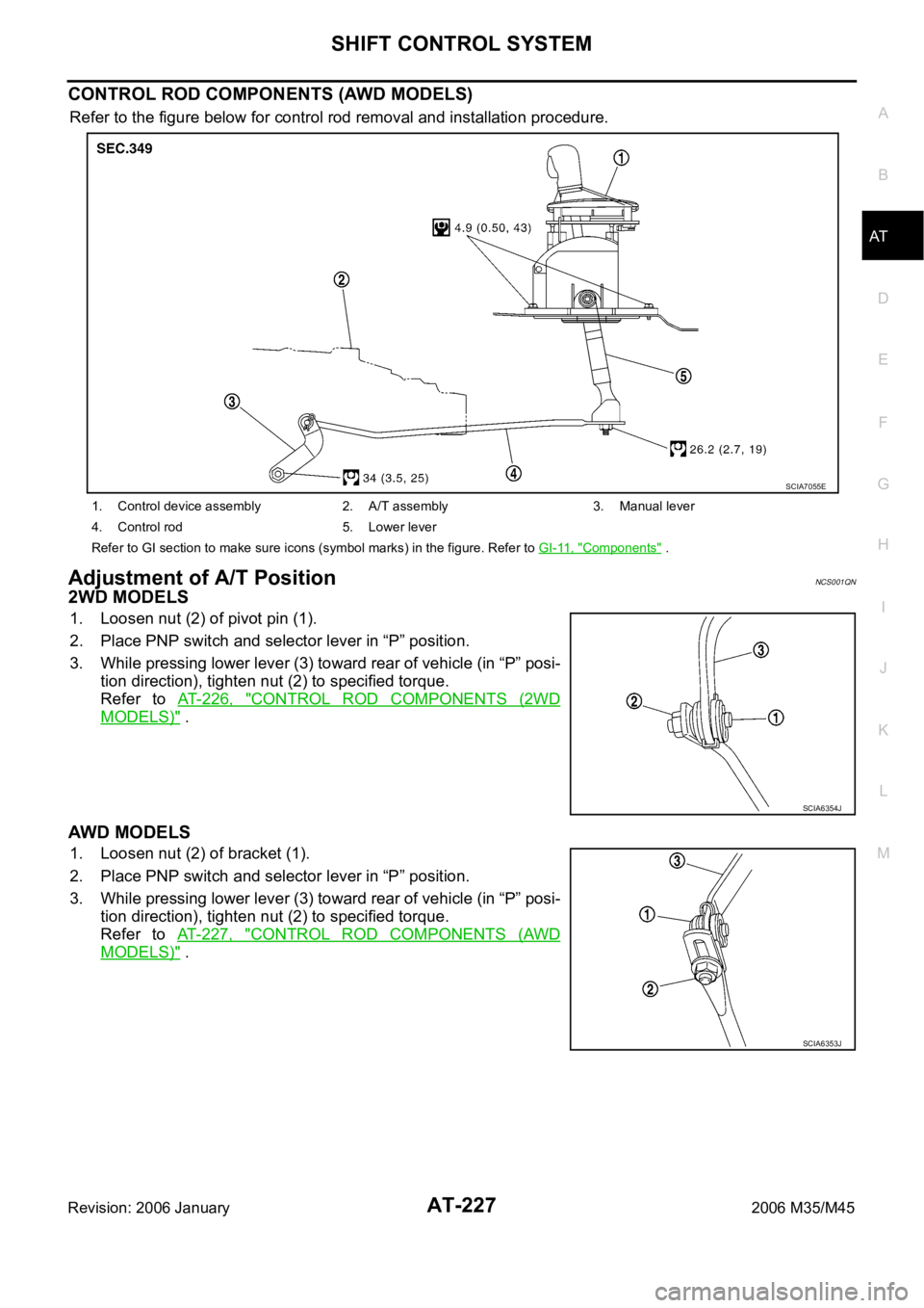
CONTROL ROD COMPONENTS (AWD MODELS)
Refer to the figure below for control rod removal and installation procedure.
Adjustment of A/T PositionNCS001QN
2WD MODELS
1. Loosen nut (2) of pivot pin (1).
2. Place PNP switch and selector lever in “P” position.
3. While pressing lower lever (3) toward rear of vehicle (in “P” posi-
tion direction), tighten nut (2) to specified torque.
Refer to AT- 2 2 6 , "
CONTROL ROD COMPONENTS (2WD
MODELS)" .
AWD MODELS
1. Loosen nut (2) of bracket (1).
2. Place PNP switch and selector lever in “P” position.
3. While pressing lower lever (3) toward rear of vehicle (in “P” posi-
tion direction), tighten nut (2) to specified torque.
Refer to AT-227, "
CONTROL ROD COMPONENTS (AWD
MODELS)" .
1. Control device assembly 2. A/T assembly 3. Manual lever
4. Control rod 5. Lower lever
Refer to GI section to make sure icons (symbol marks) in the figure. Refer to GI-11, "
Components" .
SCIA7055E
SCIA6354J
SCIA6353J
Page 307 of 5621
AT-228
SHIFT CONTROL SYSTEM
Revision: 2006 January2006 M35/M45
Checking of A/T PositionNCS001QO
1. Place selector lever in “P” position, and turn ignition switch ON (engine stop).
2. Make sure that selector lever can be shifted to other than “P” position when brake pedal is depressed.
Also make sure that selector lever can be shifted from “P” position only when brake pedal is depressed.
3. Move the selector lever and check for excessive effort, sticking, noise or rattle.
4. Confirm the selector lever stops at each position with the feel of engagement when it is moved through all
the positions. Check whether or not the actual position the selector lever is in matches the position shown
by the shift position indicator and the A/T body.
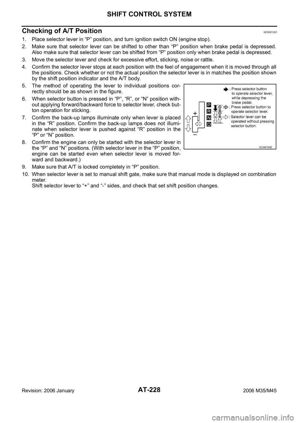
5. The method of operating the lever to individual positions cor-
rectly should be as shown in the figure.
6. When selector button is pressed in “P”, “R”, or “N” position with-
out applying forward/backward force to selector lever, check but-
ton operation for sticking.
7. Confirm the back-up lamps illuminate only when lever is placed
in the “R” position. Confirm the back-up lamps does not illumi-
nate when selector lever is pushed against “R” position in the
“P” or “N” position.
8. Confirm the engine can only be started with the selector lever in
the “P” and “N” positions. (With selector lever in the “P” position,
engine can be started even when selector lever is moved for-
ward and backward.)
9. Make sure that A/T is locked completely in “P” position.
10. When selector lever is set to manual shift gate, make sure that manual mode is displayed on combination
meter.
Shift selector lever to “+” and “-” sides, and check that set shift position changes.
SCIA6760E