checking oil INFINITI M35 2006 Factory Owners Manual
[x] Cancel search | Manufacturer: INFINITI, Model Year: 2006, Model line: M35, Model: INFINITI M35 2006Pages: 5621, PDF Size: 65.56 MB
Page 4982 of 5621
POWER STEERING OIL PUMP
PS-29
C
D
E
F
H
I
J
K
L
MA
B
PS
Revision: 2006 January2006 M35/M45
POWER STEERING OIL PUMPPFP:49110
On-Vehicle Inspection and ServiceNGS000DE
CHECKING RELIEF OIL PRESSURE
CAUTION:
Make sure that belt tension is normal before starting the following procedure.
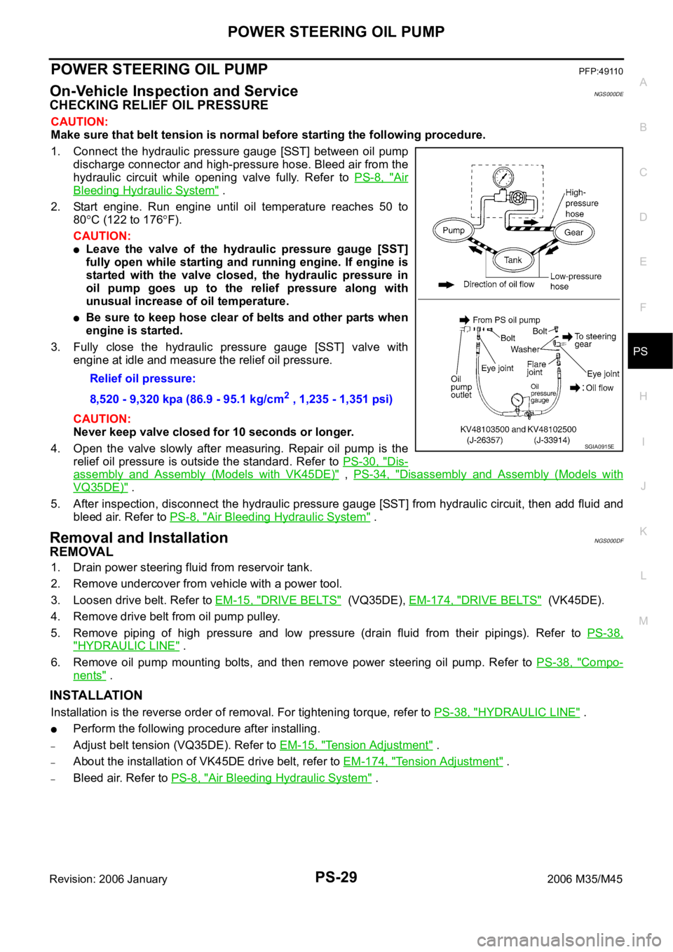
1. Connect the hydraulic pressure gauge [SST] between oil pump
discharge connector and high-pressure hose. Bleed air from the
hydraulic circuit while opening valve fully. Refer to PS-8, "
Air
Bleeding Hydraulic System" .
2. Start engine. Run engine until oil temperature reaches 50 to
80
C (122 to 176F).
CAUTION:
Leave the valve of the hydraulic pressure gauge [SST]
fully open while starting and running engine. If engine is
started with the valve closed, the hydraulic pressure in
oil pump goes up to the relief pressure along with
unusual increase of oil temperature.
Be sure to keep hose clear of belts and other parts when
engine is started.
3. Fully close the hydraulic pressure gauge [SST] valve with
engine at idle and measure the relief oil pressure.
CAUTION:
Never keep valve closed for 10 seconds or longer.
4. Open the valve slowly after measuring. Repair oil pump is the
relief oil pressure is outside the standard. Refer to PS-30, "
Dis-
assembly and Assembly (Models with VK45DE)" , PS-34, "Disassembly and Assembly (Models with
VQ35DE)" .
5. After inspection, disconnect the hydraulic pressure gauge [SST] from hydraulic circuit, then add fluid and
bleed air. Refer to PS-8, "
Air Bleeding Hydraulic System" .
Removal and InstallationNGS000DF
REMOVAL
1. Drain power steering fluid from reservoir tank.
2. Remove undercover from vehicle with a power tool.
3. Loosen drive belt. Refer to EM-15, "
DRIVE BELTS" (VQ35DE), EM-174, "DRIVE BELTS" (VK45DE).
4. Remove drive belt from oil pump pulley.
5. Remove piping of high pressure and low pressure (drain fluid from their pipings). Refer to PS-38,
"HYDRAULIC LINE" .
6. Remove oil pump mounting bolts, and then remove power steering oil pump. Refer to PS-38, "
Compo-
nents" .
INSTALLATION
Installation is the reverse order of removal. For tightening torque, refer to PS-38, "HYDRAULIC LINE" .
Perform the following procedure after installing.
–Adjust belt tension (VQ35DE). Refer to EM-15, "Tension Adjustment" .
–About the installation of VK45DE drive belt, refer to EM-174, "Tension Adjustment" .
–Bleed air. Refer to PS-8, "Air Bleeding Hydraulic System" . Relief oil pressure:
8,520 - 9,320 kpa (86.9 - 95.1 kg/cm
2 , 1,235 - 1,351 psi)
SGIA0915E
Page 5044 of 5621
RFD-1
REAR FINAL DRIVE
D DRIVELINE/AXLE
CONTENTS
C
E
F
G
H
I
J
K
L
M
SECTION RFD
A
B
RFD
Revision: 2006 January2006 M35/M45
REAR FINAL DRIVE
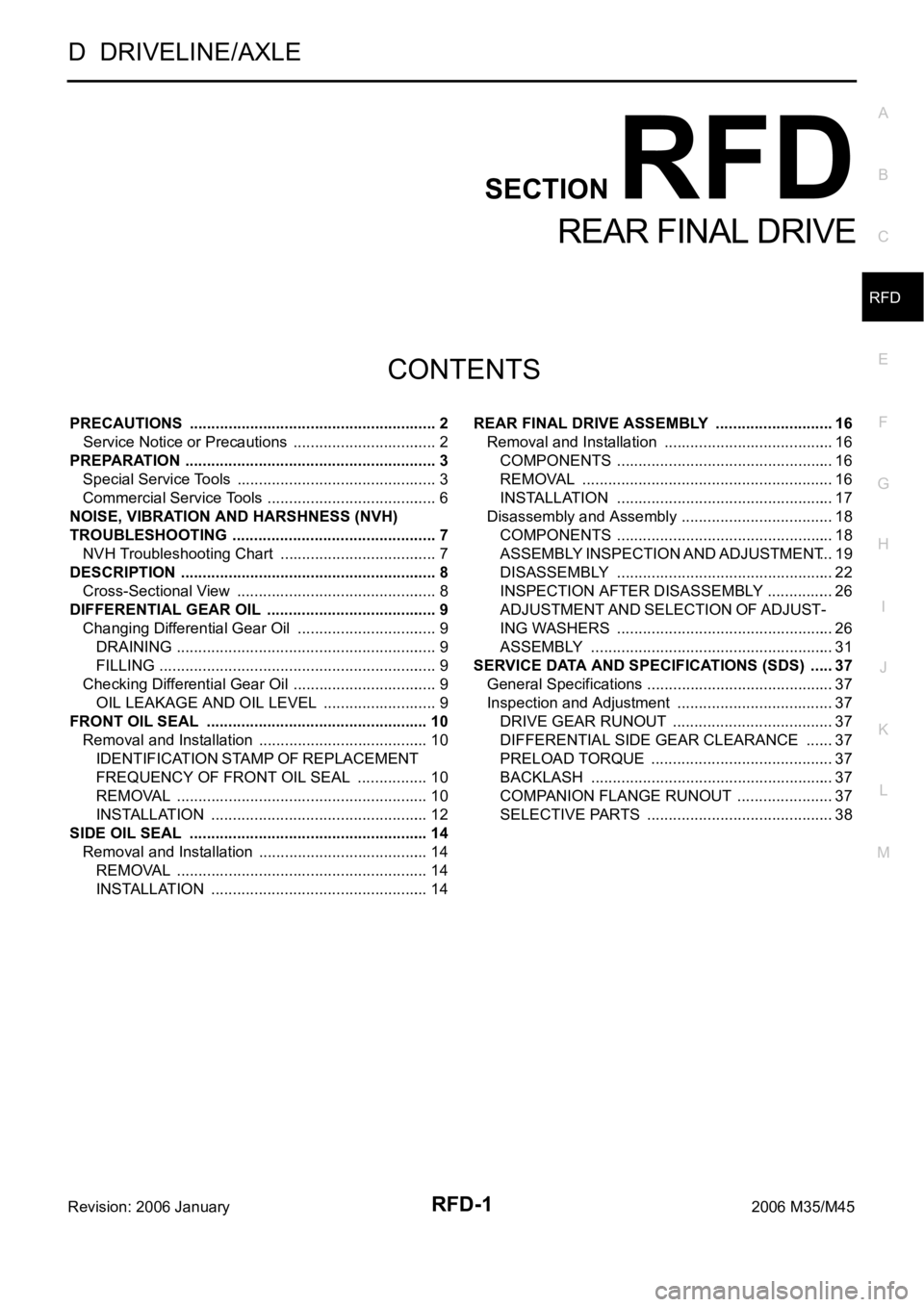
PRECAUTIONS .......................................................... 2
Service Notice or Precautions .................................. 2
PREPARATION ........................................................... 3
Special Service Tools ............................................... 3
Commercial Service Tools ........................................ 6
NOISE, VIBRATION AND HARSHNESS (NVH)
TROUBLESHOOTING ................................................ 7
NVH Troubleshooting Chart ..................................... 7
DESCRIPTION ............................................................ 8
Cross-Sectional View ............................................... 8
DIFFERENTIAL GEAR OIL ........................................ 9
Changing Differential Gear Oil ................................. 9
DRAINING ............................................................. 9
FILLING ................................................................. 9
Checking Differential Gear Oil .................................. 9
OIL LEAKAGE AND OIL LEVEL ........................... 9
FRONT OIL SEAL .................................................
... 10
Removal and Installation ........................................ 10
IDENTIFICATION STAMP OF REPLACEMENT
FREQUENCY OF FRONT OIL SEAL ................. 10
REMOVAL ........................................................
... 10
INSTALLATION ................................................... 12
SIDE OIL SEAL ........................................................ 14
Removal and Installation ........................................ 14
REMOVAL ........................................................
... 14
INSTALLATION ................................................... 14REAR FINAL DRIVE ASSEMBLY ............................ 16
Removal and Installation ........................................ 16
COMPONENTS ................................................... 16
REMOVAL ........................................................
... 16
INSTALLATION ................................................... 17
Disassembly and Assembly .................................... 18
COMPONENTS ................................................... 18
ASSEMBLY INSPECTION AND ADJUSTMENT ... 19
DISASSEMBLY ................................................... 22
INSPECTION AFTER DISASSEMBLY ................ 26
ADJUSTMENT AND SELECTION OF ADJUST-
ING WASHERS ................................................... 26
ASSEMBLY ......................................................... 31
SERVICE DATA AND SPECIFICATIONS (SDS) ...... 37
General Specifications ......................................... ... 37
Inspection and Adjustment ..................................... 37
DRIVE GEAR RUNOUT ...................................... 37
DIFFERENTIAL SIDE GEAR CLEARANCE ....... 37
PRELOAD TORQUE ........................................... 37
BACKLASH ......................................................... 37
COMPANION FLANGE RUNOUT ....................... 37
SELECTIVE PARTS ............................................ 38
Page 5050 of 5621
NOISE, VIBRATION AND HARSHNESS (NVH) TROUBLESHOOTING
RFD-7
C
E
F
G
H
I
J
K
L
MA
B
RFD
Revision: 2006 January2006 M35/M45
NOISE, VIBRATION AND HARSHNESS (NVH) TROUBLESHOOTINGPFP:00003
NVH Troubleshooting ChartNDS000F1
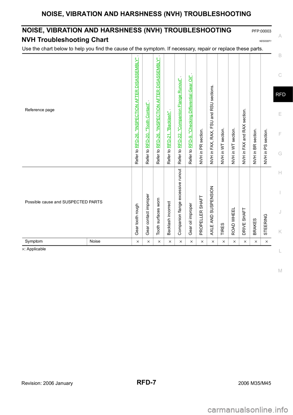
Use the chart below to help you find the cause of the symptom. If necessary, repair or replace these parts.
: ApplicableReference page
Refer to RFD-26, "
INSPECTION AFTER DISASSEMBLY
" .
Refer to RFD-20, "
Tooth Contact
" .
Refer to RFD-26, "
INSPECTION AFTER DISASSEMBLY
" .
Refer to RFD-21, "
Backlash
" .
Refer to RFD-22, "
Companion Flange Runout
" .
Refer to RFD-9, "
Checking Differential Gear Oil
" .
NVH in PR section.
NVH in FAX, RAX, FSU and RSU sections.
NVH in WT section.
NVH in WT section.
NVH in FAX and RAX section.
NVH in BR section.
NVH in PS section.
Possible cause and SUSPECTED PARTS
Gear tooth rough
Gear contact improper
Tooth surfaces worn
Backlash incorrect
Companion flange excessive runout
Gear oil improper
PROPELLER SHAFT
AXLE AND SUSPENSION
TIRES
ROAD WHEEL
DRIVE SHAFT
BRAKES
STEERING
Symptom Noise
Page 5052 of 5621
DIFFERENTIAL GEAR OIL
RFD-9
C
E
F
G
H
I
J
K
L
MA
B
RFD
Revision: 2006 January2006 M35/M45
DIFFERENTIAL GEAR OILPFP:KLD30
Changing Differential Gear OilNDS000F3
DRAINING
1. Stop engine.
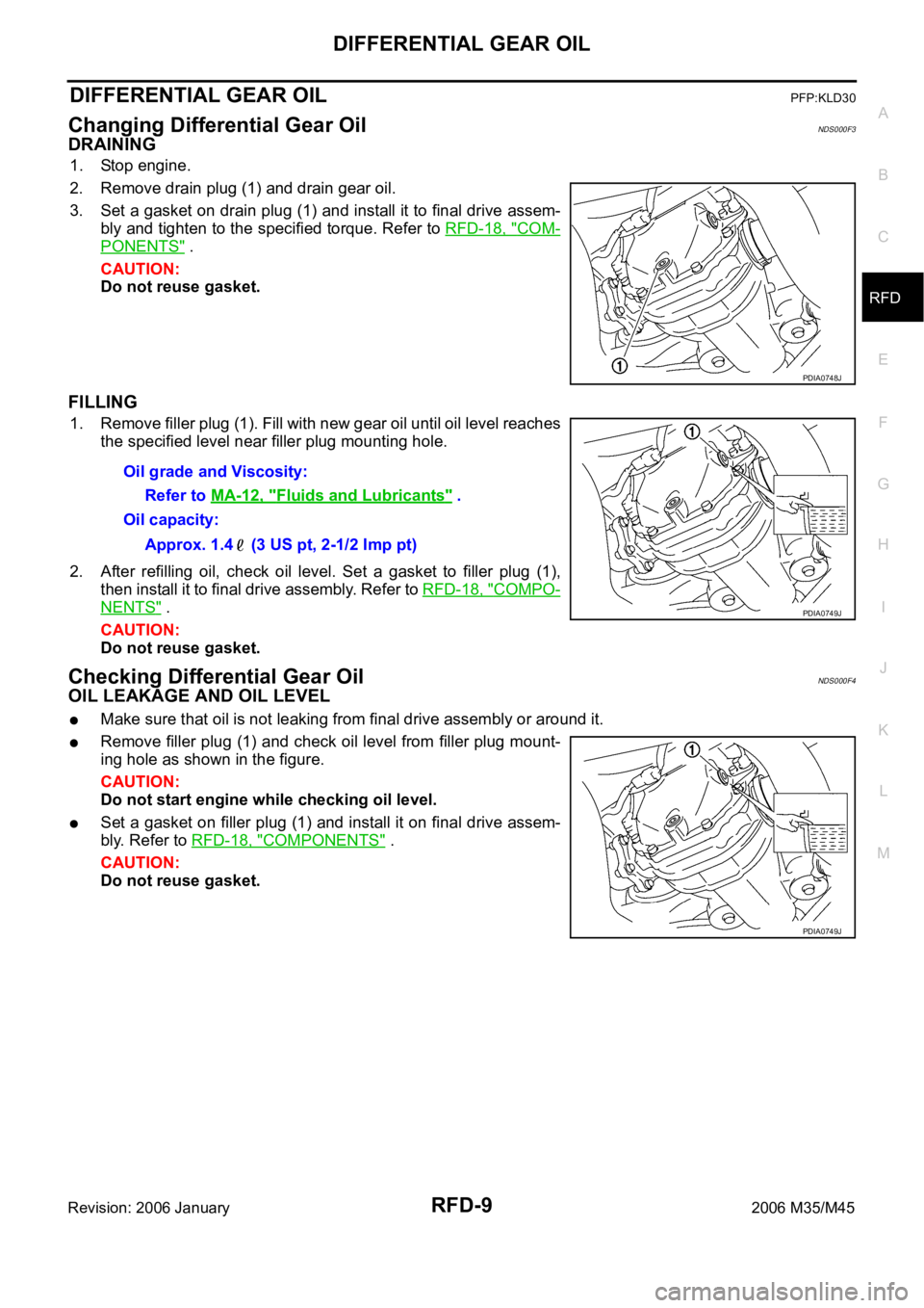
2. Remove drain plug (1) and drain gear oil.
3. Set a gasket on drain plug (1) and install it to final drive assem-
bly and tighten to the specified torque. Refer to RFD-18, "
COM-
PONENTS" .
CAUTION:
Do not reuse gasket.
FILLING
1. Remove filler plug (1). Fill with new gear oil until oil level reaches
the specified level near filler plug mounting hole.
2. After refilling oil, check oil level. Set a gasket to filler plug (1),
then install it to final drive assembly. Refer to RFD-18, "
COMPO-
NENTS" .
CAUTION:
Do not reuse gasket.
Checking Differential Gear OilNDS000F4
OIL LEAKAGE AND OIL LEVEL
Make sure that oil is not leaking from final drive assembly or around it.
Remove filler plug (1) and check oil level from filler plug mount-
ing hole as shown in the figure.
CAUTION:
Do not start engine while checking oil level.
Set a gasket on filler plug (1) and install it on final drive assem-
bly. Refer to RFD-18, "
COMPONENTS" .
CAUTION:
Do not reuse gasket.
PDIA0748J
Oil grade and Viscosity:
Refer to MA-12, "
Fluids and Lubricants" .
Oil capacity:
Approx. 1.4 (3 US pt, 2-1/2 Imp pt)
PDIA0749J
PDIA0749J
Page 5058 of 5621
SIDE OIL SEAL
RFD-15
C
E
F
G
H
I
J
K
L
MA
B
RFD
Revision: 2006 January2006 M35/M45
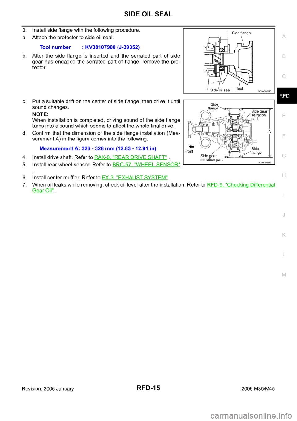
3. Install side flange with the following procedure.
a. Attach the protector to side oil seal.
b. After the side flange is inserted and the serrated part of side
gear has engaged the serrated part of flange, remove the pro-
tector.
c. Put a suitable drift on the center of side flange, then drive it until
sound changes.
NOTE:
When installation is completed, driving sound of the side flange
turns into a sound which seems to affect the whole final drive.
d. Confirm that the dimension of the side flange installation (Mea-
surement A) in the figure comes into the following.
4. Install drive shaft. Refer to RAX-8, "
REAR DRIVE SHAFT" .
5. Install rear wheel sensor. Refer to BRC-57, "
WHEEL SENSOR"
.
6. Install center muffler. Refer to EX-3, "
EXHAUST SYSTEM" .
7. When oil leaks while removing, check oil level after the installation. Refer to RFD-9, "
Checking Differential
Gear Oil" . Tool number : KV38107900 (J-39352)
SDIA0822E
Measurement A: 326 - 328 mm (12.83 - 12.91 in)
SDIA1039E
Page 5060 of 5621
REAR FINAL DRIVE ASSEMBLY
RFD-17
C
E
F
G
H
I
J
K
L
MA
B
RFD
Revision: 2006 January2006 M35/M45
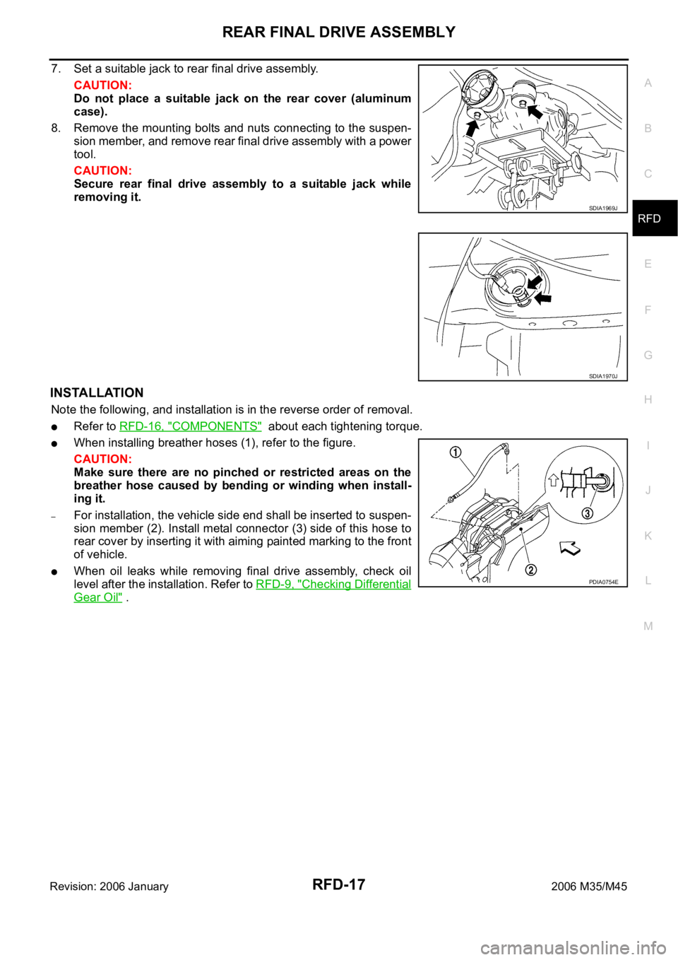
7. Set a suitable jack to rear final drive assembly.
CAUTION:
Do not place a suitable jack on the rear cover (aluminum
case).
8. Remove the mounting bolts and nuts connecting to the suspen-
sion member, and remove rear final drive assembly with a power
tool.
CAUTION:
Secure rear final drive assembly to a suitable jack while
removing it.
INSTALLATION
Note the following, and installation is in the reverse order of removal.
Refer to RFD-16, "COMPONENTS" about each tightening torque.
When installing breather hoses (1), refer to the figure.
CAUTION:
Make sure there are no pinched or restricted areas on the
breather hose caused by bending or winding when install-
ing it.
–For installation, the vehicle side end shall be inserted to suspen-
sion member (2). Install metal connector (3) side of this hose to
rear cover by inserting it with aiming painted marking to the front
of vehicle.
When oil leaks while removing final drive assembly, check oil
level after the installation. Refer to RFD-9, "
Checking Differential
Gear Oil" .
SDIA1969J
SDIA1970J
PDIA0754E
Page 5089 of 5621
RSU-8
REAR SUSPENSION ASSEMBLY
Revision: 2006 January2006 M35/M45
Refer to GI section for symbol marks in the figure. Refer to GI-9, "HOW TO USE THIS MANUAL" .
Removal and InstallationNES000J9
REMOVAL
1. Remove tire with a power tool.
2. Remove brake caliper with a power tool. Hang it in a place where it will not interfere with work. Refer to
BR-29, "
REAR DISC BRAKE" .
CAUTION:
Do not depressing brake pedal while brake caliper is removed.
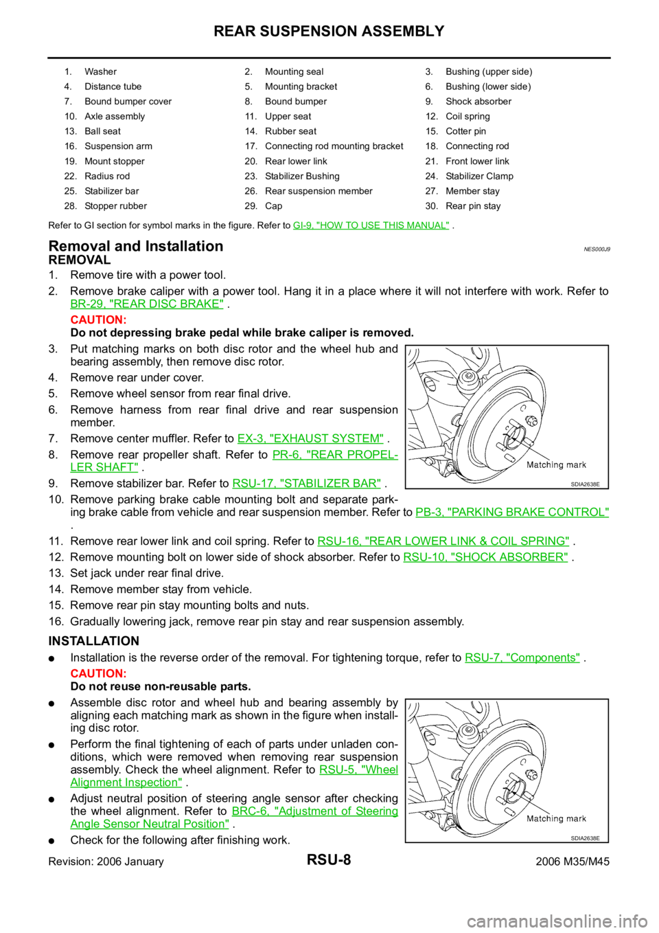
3. Put matching marks on both disc rotor and the wheel hub and
bearing assembly, then remove disc rotor.
4. Remove rear under cover.
5. Remove wheel sensor from rear final drive.
6. Remove harness from rear final drive and rear suspension
member.
7. Remove center muffler. Refer to EX-3, "
EXHAUST SYSTEM" .
8. Remove rear propeller shaft. Refer to PR-6, "
REAR PROPEL-
LER SHAFT" .
9. Remove stabilizer bar. Refer to RSU-17, "
STABILIZER BAR" .
10. Remove parking brake cable mounting bolt and separate park-
ing brake cable from vehicle and rear suspension member. Refer to PB-3, "
PARKING BRAKE CONTROL"
.
11. Remove rear lower link and coil spring. Refer to RSU-16, "
REAR LOWER LINK & COIL SPRING" .
12. Remove mounting bolt on lower side of shock absorber. Refer to RSU-10, "
SHOCK ABSORBER" .
13. Set jack under rear final drive.
14. Remove member stay from vehicle.
15. Remove rear pin stay mounting bolts and nuts.
16. Gradually lowering jack, remove rear pin stay and rear suspension assembly.
INSTALLATION
Installation is the reverse order of the removal. For tightening torque, refer to RSU-7, "Components" .
CAUTION:
Do not reuse non-reusable parts.
Assemble disc rotor and wheel hub and bearing assembly by
aligning each matching mark as shown in the figure when install-
ing disc rotor.
Perform the final tightening of each of parts under unladen con-
ditions, which were removed when removing rear suspension
assembly. Check the wheel alignment. Refer to RSU-5, "
Wheel
Alignment Inspection" .
Adjust neutral position of steering angle sensor after checking
the wheel alignment. Refer to BRC-6, "
Adjustment of Steering
Angle Sensor Neutral Position" .
Check for the following after finishing work.
1. Washer 2. Mounting seal 3. Bushing (upper side)
4. Distance tube 5. Mounting bracket 6. Bushing (lower side)
7. Bound bumper cover 8. Bound bumper 9. Shock absorber
10. Axle assembly 11. Upper seat 12. Coil spring
13. Ball seat 14. Rubber seat 15. Cotter pin
16. Suspension arm 17. Connecting rod mounting bracket 18. Connecting rod
19. Mount stopper 20. Rear lower link 21. Front lower link
22. Radius rod 23. Stabilizer Bushing 24. Stabilizer Clamp
25. Stabilizer bar 26. Rear suspension member 27. Member stay
28. Stopper rubber 29. Cap 30. Rear pin stay
SDIA2638E
SDIA2638E
Page 5091 of 5621
RSU-10
SHOCK ABSORBER
Revision: 2006 January2006 M35/M45
SHOCK ABSORBERPFP:56210
Removal and InstallationNES000JA
REMOVAL
1. Remove tires from vehicle with a power tool.
2. Set a jack under rear lower link to relieve the coil spring tension.
3. Remove shock absorber lower end bolt with a power tool.
4. Gradually lower the jack to remove it from rear lower link.
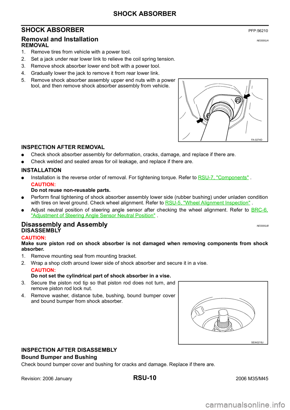
5. Remove shock absorber assembly upper end nuts with a power
tool, and then remove shock absorber assembly from vehicle.
INSPECTION AFTER REMOVAL
Check shock absorber assembly for deformation, cracks, damage, and replace if there are.
Check welded and sealed areas for oil leakage, and replace if there are.
INSTALLATION
Installation is the reverse order of removal. For tightening torque. Refer to RSU-7, "Components" .
CAUTION:
Do not reuse non-reusable parts.
Perform final tightening of shock absorber assembly lower side (rubber bushing) under unladen condition
with tires on level ground. Check wheel alignment. Refer to RSU-5, "
Wheel Alignment Inspection" .
Adjust neutral position of steering angle sensor after checking the wheel alignment. Refer to BRC-6,
"Adjustment of Steering Angle Sensor Neutral Position" .
Disassembly and AssemblyNES000JB
DISASSEMBLY
CAUTION:
Make sure piston rod on shock absorber is not damaged when removing components from shock
absorber.
1. Remove mounting seal from mounting bracket.
2. Wrap a shop cloth around lower side of shock absorber and secure it in a vise.
CAUTION:
Do not set the cylindrical part of shock absorber in a vise.
3. Secure the piston rod tip so that piston rod does not turn, and
remove piston rod lock nut.
4. Remove washer, distance tube, bushing, bound bumper cover
and bound bumper from shock absorber.
INSPECTION AFTER DISASSEMBLY
Bound Bumper and Bushing
Check bound bumper cover and bushing for cracks and damage. Replace if there are.
FA-0274D
SEIA0218J
Page 5095 of 5621
RSU-14
RADIUS ROD
Revision: 2006 January2006 M35/M45
RADIUS RODPFP:55110
Removal and InstallationNES000JD
REMOVAL
1. Remove tire with a power tool.
2. Remove brake caliper with a power tool. Hang it in a place where it will not interfere with work. Refer to
BR-29, "
REAR DISC BRAKE" .
CAUTION:
Do not depressing brake pedal while brake caliper is removed.
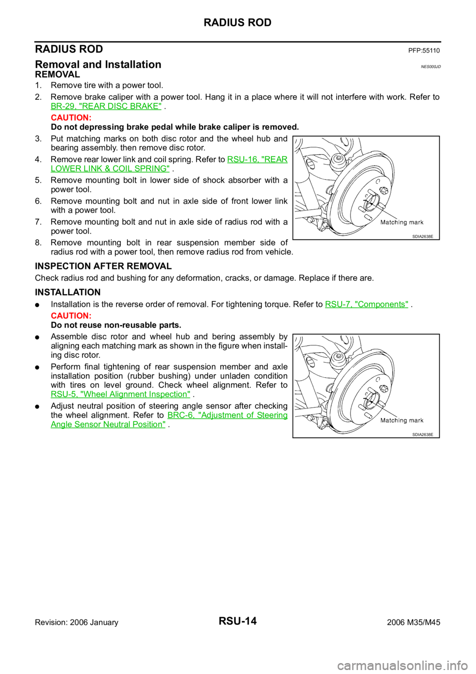
3. Put matching marks on both disc rotor and the wheel hub and
bearing assembly. then remove disc rotor.
4. Remove rear lower link and coil spring. Refer to RSU-16, "
REAR
LOWER LINK & COIL SPRING" .
5. Remove mounting bolt in lower side of shock absorber with a
power tool.
6. Remove mounting bolt and nut in axle side of front lower link
with a power tool.
7. Remove mounting bolt and nut in axle side of radius rod with a
power tool.
8. Remove mounting bolt in rear suspension member side of
radius rod with a power tool, then remove radius rod from vehicle.
INSPECTION AFTER REMOVAL
Check radius rod and bushing for any deformation, cracks, or damage. Replace if there are.
INSTALLATION
Installation is the reverse order of removal. For tightening torque. Refer to RSU-7, "Components" .
CAUTION:
Do not reuse non-reusable parts.
Assemble disc rotor and wheel hub and bering assembly by
aligning each matching mark as shown in the figure when install-
ing disc rotor.
Perform final tightening of rear suspension member and axle
installation position (rubber bushing) under unladen condition
with tires on level ground. Check wheel alignment. Refer to
RSU-5, "
Wheel Alignment Inspection" .
Adjust neutral position of steering angle sensor after checking
the wheel alignment. Refer to BRC-6, "
Adjustment of Steering
Angle Sensor Neutral Position" .
SDIA2638E
SDIA2638E
Page 5096 of 5621
FRONT LOWER LINK
RSU-15
C
D
F
G
H
I
J
K
L
MA
B
RSU
Revision: 2006 January2006 M35/M45
FRONT LOWER LINKPFP:55110
Removal and InstallationNES000JE
REMOVAL
1. Remove tire with a power tool.
2. Set a jack under rear lower link to relieve the coil spring tension.
3. Remove mounting nut and bolt between front lower link and rear suspension member with a power tool.
4. Remove mounting nut and bolt between front lower link and axle with a power tool.
5. Remove front lower link from vehicle.
INSPECTION AFTER REMOVAL
Check front lower link and bushing for any deformation, cracks, or damage. Replace if there are.
INSTALLATION
Installation is the reverse order of removal. For tightening torque. Refer to RSU-7, "Components" .
CAUTION:
Do not reuse non-reusable parts.
Perform the final tightening of rear suspension member and axle installation position (rubber bushing)
under unladen condition with tires on level ground. Check wheel alignment. Refer to RSU-5, "
Wheel Align-
ment Inspection" .
Adjust neutral position of steering angle sensor after checking the wheel alignment. Refer to Refer to
BRC-6, "
Adjustment of Steering Angle Sensor Neutral Position" .