manual transmission INFINITI M35 2006 Factory Service Manual
[x] Cancel search | Manufacturer: INFINITI, Model Year: 2006, Model line: M35, Model: INFINITI M35 2006Pages: 5621, PDF Size: 65.56 MB
Page 114 of 5621
A/T CONTROL SYSTEM
AT-35
D
E
F
G
H
I
J
K
L
MA
B
AT
Revision: 2006 January2006 M35/M45
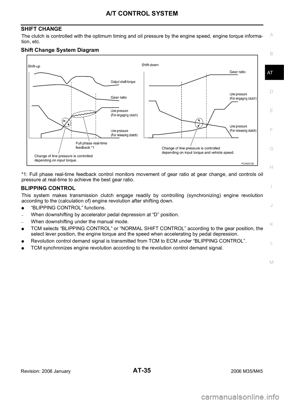
SHIFT CHANGE
The clutch is controlled with the optimum timing and oil pressure by the engine speed, engine torque informa-
tion, etc.
Shift Change System Diagram
*1: Full phase real-time feedback control monitors movement of gear ratio at gear change, and controls oil
pressure at real-time to achieve the best gear ratio.
BLIPPING CONTROL
This system makes transmission clutch engage readily by controlling (synchronizing) engine revolution
according to the (calculation of) engine revolution after shifting down.
“BLIPPING CONTROL” functions.
–When downshifting by accelerator pedal depression at “D” position.
–When downshifting under the manual mode.
TCM selects “BLIPPING CONTROL” or “NORMAL SHIFT CONTROL” according to the gear position, the
select lever position, the engine torque and the speed when accelerating by pedal depression.
Revolution control demand signal is transmitted from TCM to ECM under “BLIPPING CONTROL”.
TCM synchronizes engine revolution according to the revolution control demand signal.
PCIA0013E
Page 318 of 5621
ON-VEHICLE SERVICE
AT-239
D
E
F
G
H
I
J
K
L
MA
B
AT
Revision: 2006 January2006 M35/M45
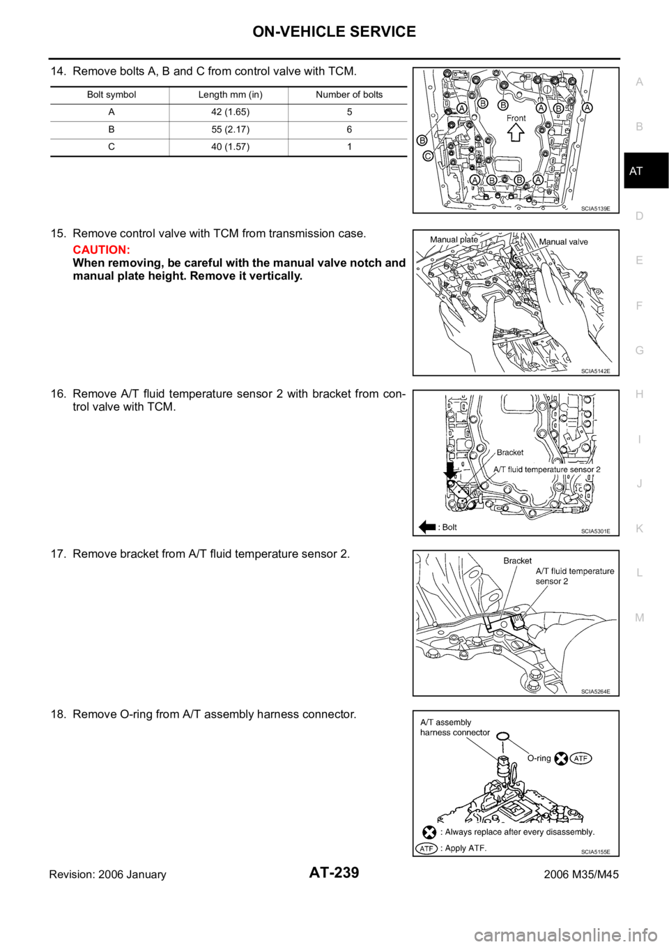
14. Remove bolts A, B and C from control valve with TCM.
15. Remove control valve with TCM from transmission case.
CAUTION:
When removing, be careful with the manual valve notch and
manual plate height. Remove it vertically.
16. Remove A/T fluid temperature sensor 2 with bracket from con-
trol valve with TCM.
17. Remove bracket from A/T fluid temperature sensor 2.
18. Remove O-ring from A/T assembly harness connector.
Bolt symbol Length mm (in) Number of bolts
A 42 (1.65) 5
B 55 (2.17) 6
C 40 (1.57) 1
SCIA5139E
SCIA5142E
SCIA5301E
SCIA5264E
SCIA5155E
Page 321 of 5621
AT-242
ON-VEHICLE SERVICE
Revision: 2006 January2006 M35/M45
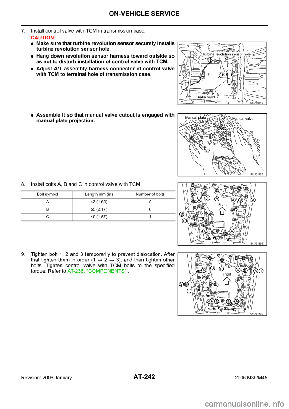
7. Install control valve with TCM in transmission case.
CAUTION:
Make sure that turbine revolution sensor securely installs
turbine revolution sensor hole.
Hang down revolution sensor harness toward outside so
as not to disturb installation of control valve with TCM.
Adjust A/T assembly harness connector of control valve
with TCM to terminal hole of transmission case.
Assemble it so that manual valve cutout is engaged with
manual plate projection.
8. Install bolts A, B and C in control valve with TCM.
9. Tighten bolt 1, 2 and 3 temporarily to prevent dislocation. After
that tighten them in order (1
2 3), and then tighten other
bolts. Tighten control valve with TCM bolts to the specified
torque. Refer to AT-236, "
COMPONENTS" .
SCIA5034E
SCIA5142E
Bolt symbol Length mm (in) Number of bolts
A 42 (1.65) 5
B 55 (2.17) 6
C 40 (1.57) 1
SCIA5139E
SCIA5140E
Page 366 of 5621

OVERHAUL
AT-287
D
E
F
G
H
I
J
K
L
MA
B
AT
Revision: 2006 January2006 M35/M45
7. Pawl shaft 8. Seal ring 9. Needle bearing
10. Revolution sensor 11. Parking gear 12. Output shaft
13. Bearing race 14. Needle bearing 15. Manual plate
16. Parking rod 17. Manual shaft oil seal 18. Manual shaft
19. O-ring 20. Band servo anchor end pin 21. Detent spring
22. Spacer 23. Seal ring 24. Snap ring
25. Return spring 26. O-ring 27. Servo assembly
28. Snap ring 29. Sub-harness 30. Control valve with TCM
31. Bracket 32. A/T fluid temperature sensor 2 33. Oil pan
34. Magnet 35. Drain plug 36. Drain plug gasket
37. Oil pan mounting bolt 38. Oil pan gasket 39. Terminal cord assembly
40. O-ring 41. Retaining pin 42. Transmission case
Refer to GI section to make sure icons (symbol marks) in the figure. Refer to GI-11, "
Components" .
However, refer to the following symbols for others.
*:Apply Genuine Anaerobic Liquid Gasket or equivalent. Refer to GI-48, "Recommended Chemical Products and Sealants"
.
Page 368 of 5621

OVERHAUL
AT-289
D
E
F
G
H
I
J
K
L
MA
B
AT
Revision: 2006 January2006 M35/M45
1. Output shaft & companion flange
complement2. Parking actuator support 3. Parking pawl
4. Return spring 5. Pawl shaft 6. Self-sealing bolt
7. Seal ring 8. Needle bearing 9. Revolution sensor
10. Intermediate shaft 11. Manual plate 12. Parking rod
13. Manual shaft oil seal 14. Manual shaft 15. Retaining pin
16. O-ring 17. Band servo anchor end pin 18. Detent spring
19. Spacer 20. Return spring 21. Seal ring
22. O-ring 23. Servo assembly 24. Snap ring
25. Snap ring 26. Sub-harness 27. Control valve with TCM
28. Bracket 29. A/T fluid temperature sensor 2 30. Terminal cord assembly
31. O-ring 32. Oil pan 33. Magnet
34. Drain plug 35. Drain plug gasket 36. Oil pan mounting bolt
37. Oil pan gasket 38. Transmission case
Refer to GI section to make sure icons (symbol marks) in the figure. Refer to GI-11, "
Components" .
However, refer to the following symbols for others.
*:Apply Genuine Anaerobic Liquid Gasket or equivalent. Refer to GI-48, "Recommended Chemical Products and Sealants" .
Page 370 of 5621

OVERHAUL
AT-291
D
E
F
G
H
I
J
K
L
MA
B
AT
Revision: 2006 January2006 M35/M45
7. Pawl shaft 8. Self-sealing bolt 9. Seal ring
10. Needle bearing 11. Gasket 12. Revolution sensor
13. Parking gear 14. Output shaft 15. Bearing race
16. Needle bearing 17. Manual plate 18. Parking rod
19. Manual shaft oil seal 20. Manual shaft 21. O-ring
22. Band servo anchor end pin 23. Detent spring 24. Spacer
25. Seal ring 26. Snap ring 27. Return spring
28. O-ring 29. Servo assembly 30. Snap ring
31. Sub-harness 32. Control valve with TCM 33. Bracket
34. A/T fluid temperature sensor 2 35. Oil pan 36. Magnet
37. Drain plug 38. Drain plug gasket 39. Oil pan mounting bolt
40. Oil pan gasket 41. Terminal cord assembly 42. O-ring
43. Retaining pin 44. Transmission case
Refer to GI section to make sure icons (symbol marks) in the figure. Refer to GI-11, "
Components" .
Page 384 of 5621
DISASSEMBLY
AT-305
D
E
F
G
H
I
J
K
L
MA
B
AT
Revision: 2006 January2006 M35/M45
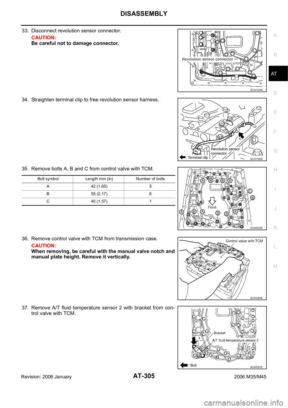
33. Disconnect revolution sensor connector.
CAUTION:
Be careful not to damage connector.
34. Straighten terminal clip to free revolution sensor harness.
35. Remove bolts A, B and C from control valve with TCM.
36. Remove control valve with TCM from transmission case.
CAUTION:
When removing, be careful with the manual valve notch and
manual plate height. Remove it vertically.
37. Remove A/T fluid temperature sensor 2 with bracket from con-
trol valve with TCM.
SCIA7524E
SCIA7526E
Bolt symbol Length mm (in) Number of bolts
A 42 (1.65) 5
B 55 (2.17) 6
C 40 (1.57) 1
SCIA5025E
SCIA5260E
SCIA5301E
Page 393 of 5621

AT-314
DISASSEMBLY
Revision: 2006 January2006 M35/M45
57. Remove manual shaft retaining pin with a pair of nippers.
58. Remove manual plate (with parking rod) from manual shaft.
59. Remove parking rod from manual plate.
60. Remove manual shaft from transmission case.
61. Remove manual shaft oil seals using a flat-bladed screwdriver.
CAUTION:
Be careful not to scratch transmission case.
SCIA2329E
SCIA5715E
SCIA5220E
SCIA5716E
SCIA2331E
Page 419 of 5621
![INFINITI M35 2006 Factory Service Manual AT-340
ASSEMBLY
Revision: 2006 January2006 M35/M45
ASSEMBLYPFP:00000
Assembly (1)NCS001RA
1. As shown in the figure, use a drift [22 mm (0.87 in) dia. commer-
cial service tool] to drive manual shaft INFINITI M35 2006 Factory Service Manual AT-340
ASSEMBLY
Revision: 2006 January2006 M35/M45
ASSEMBLYPFP:00000
Assembly (1)NCS001RA
1. As shown in the figure, use a drift [22 mm (0.87 in) dia. commer-
cial service tool] to drive manual shaft](/img/42/57023/w960_57023-418.png)
AT-340
ASSEMBLY
Revision: 2006 January2006 M35/M45
ASSEMBLYPFP:00000
Assembly (1)NCS001RA
1. As shown in the figure, use a drift [22 mm (0.87 in) dia. commer-
cial service tool] to drive manual shaft oil seals into the transmis-
sion case until it is flush.
CAUTION:
Apply ATF to manual shaft oil seals.
Do not reuse manual shaft oil seals.
2. Install detent spring and spacer in transmission case. Tighten
detent spring and spacer bolts to the specified torque. Refer to
AT-278, "
Components" .
3. Install manual shaft to transmission case.
4. Install parking rod to manual plate.
SCIA5259E
SCIA5248E
SCIA5716E
SCIA5220E
Page 420 of 5621
ASSEMBLY
AT-341
D
E
F
G
H
I
J
K
L
MA
B
AT
Revision: 2006 January2006 M35/M45
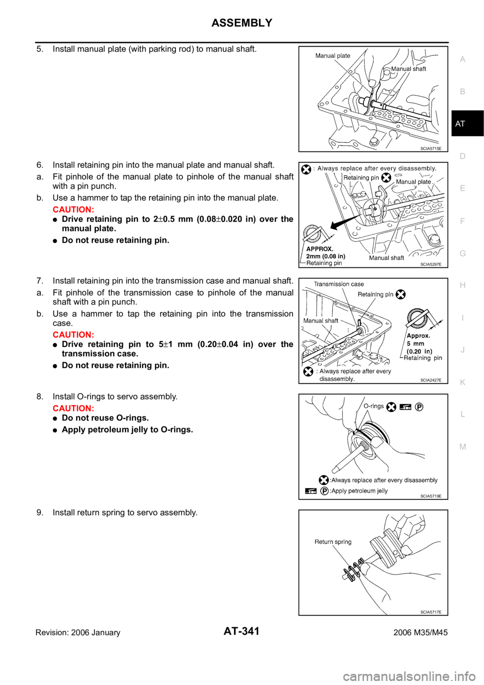
5. Install manual plate (with parking rod) to manual shaft.
6. Install retaining pin into the manual plate and manual shaft.
a. Fit pinhole of the manual plate to pinhole of the manual shaft
with a pin punch.
b. Use a hammer to tap the retaining pin into the manual plate.
CAUTION:
Drive retaining pin to 20.5 mm (0.080.020 in) over the
manual plate.
Do not reuse retaining pin.
7. Install retaining pin into the transmission case and manual shaft.
a. Fit pinhole of the transmission case to pinhole of the manual
shaft with a pin punch.
b. Use a hammer to tap the retaining pin into the transmission
case.
CAUTION:
Drive retaining pin to 51 mm (0.200.04 in) over the
transmission case.
Do not reuse retaining pin.
8. Install O-rings to servo assembly.
CAUTION:
Do not reuse O-rings.
Apply petroleum jelly to O-rings.
9. Install return spring to servo assembly.
SCIA5715E
SCIA5297E
SCIA2427E
SCIA5719E
SCIA5717E