combination meter INFINITI M35 2006 Factory Owners Manual
[x] Cancel search | Manufacturer: INFINITI, Model Year: 2006, Model line: M35, Model: INFINITI M35 2006Pages: 5621, PDF Size: 65.56 MB
Page 2863 of 5621
![INFINITI M35 2006 Factory Owners Manual EC-1320
[VK45DE]
DTC P1574 ICC VEHICLE SPEED SENSOR
Revision: 2006 January2006 M35/M45
Diagnostic ProcedureNBS005N5
1. CHECK DTC WITH TCM
Check DTC with TCM. Refer to AT- 4 0 , "
OBD-II Diagnost INFINITI M35 2006 Factory Owners Manual EC-1320
[VK45DE]
DTC P1574 ICC VEHICLE SPEED SENSOR
Revision: 2006 January2006 M35/M45
Diagnostic ProcedureNBS005N5
1. CHECK DTC WITH TCM
Check DTC with TCM. Refer to AT- 4 0 , "
OBD-II Diagnost](/img/42/57023/w960_57023-2862.png)
EC-1320
[VK45DE]
DTC P1574 ICC VEHICLE SPEED SENSOR
Revision: 2006 January2006 M35/M45
Diagnostic ProcedureNBS005N5
1. CHECK DTC WITH TCM
Check DTC with TCM. Refer to AT- 4 0 , "
OBD-II Diagnostic Trouble Code (DTC)" .
OK or NG
OK >> GO TO 2.
NG >> Perform trouble shooting relevant to DTC indicated.
2. CHECK DTC WITH “ABS ACTUATOR AND ELECTRIC UNIT (CONTROL UNIT)”
Refer to BRC-11, "
TROUBLE DIAGNOSIS" .
OK or NG
OK >> GO TO 3.
NG >> Repair or replace.
3. CHECK DTC WITH “UNIFIED METER AND A/C AMP.”
Check combination meter function.
Refer to DI-28, "
UNIFIED METER AND A/C AMP" .
>>INSPECTION END
Page 2999 of 5621
![INFINITI M35 2006 Factory Owners Manual EC-1456
[VK45DE]
ASCD INDICATOR
Revision: 2006 January2006 M35/M45
ASCD INDICATORPFP:24814
Component DescriptionNBS005QO
ASCD indicator lamp illuminates to indicate ASCD operation status. Lam INFINITI M35 2006 Factory Owners Manual EC-1456
[VK45DE]
ASCD INDICATOR
Revision: 2006 January2006 M35/M45
ASCD INDICATORPFP:24814
Component DescriptionNBS005QO
ASCD indicator lamp illuminates to indicate ASCD operation status. Lam](/img/42/57023/w960_57023-2998.png)
EC-1456
[VK45DE]
ASCD INDICATOR
Revision: 2006 January2006 M35/M45
ASCD INDICATORPFP:24814
Component DescriptionNBS005QO
ASCD indicator lamp illuminates to indicate ASCD operation status. Lamp has two indicators, CRUISE and
SET, and is integrated in combination meter.
CRUISE lamp illuminates when MAIN switch on ASCD steering switch is turned ON to indicated that ASCD
system is ready for operation.
SET lamp illuminates when following conditions are met.
CRUISE lamp is illuminated.
SET/COAST switch on ASCD steering switch is turned ON while vehicle speed is within the range of
ASCD setting.
SET lamp remains lit during ASCD control.
Refer to EC-746, "
AUTOMATIC SPEED CONTROL DEVICE (ASCD)" for the ASCD function.
CONSULT-II Reference Value in Data Monitor ModeNBS005QP
Specification data are reference values.
MONITOR ITEM CONDITION SPECIFICATION
CRUISE LAMP
Ignition switch: ONMAIN switch: Pressed at the 1st time
at the 2nd timeON OFF
SET LAMP
MAIN switch: ON
When vehicle speed is between
40 km/h (25 MPH) and 144 km/h
(89 MPH)ASCD: Operating ON
ASCD: Not operating OFF
Page 3012 of 5621
SQUEAK AND RATTLE TROUBLE DIAGNOSES
EI-7
C
D
E
F
G
H
J
K
L
MA
B
EI
Revision: 2006 January2006 M35/M45
INSULATOR (Light foam block)
80845-71L00: 30 mm (1.18 in) thick, 30
50 mm (1.181.97 in)
FELT CLOTHTAPE
Used to insulate where movement does not occur. Ideal for instrument panel applications.
68370-4B000: 15
25 mm (0.590.98 in) pad/68239-13E00: 5 mm (0.20 in) wide tape roll
The following materials, not found in the kit, can also be used to repair squeaks and rattles.
UHMW (TEFLON) TAPE
Insulates where slight movement is present. Ideal for instrument panel applications.
SILICONE GREASE
Used in place of UHMW tape that will be visible or not fit. Will only last a few months.
SILICONE SPRAY
Use when grease cannot be applied.
DUCT TAPE
Use to eliminate movement.
CONFIRM THE REPAIR
Confirm that the cause of a noise is repaired by test driving the vehicle. Operate the vehicle under the same
conditions as when the noise originally occurred. Refer to the notes on the Diagnostic Worksheet.
Generic Squeak and Rattle TroubleshootingNIS0024B
Refer to Table of Contents for specific component removal and installation information.
INSTRUMENT PANEL
Most incidents are caused by contact and movement between:
1. The cluster lid A and instrument panel
2. Acrylic lens and combination meter housing
3. Instrument panel to front pillar garnish
4. Instrument panel to windshield
5. Instrument panel mounting pins
6. Wiring harnesses behind the combination meter
7. A/C defroster duct and duct joint
These incidents can usually be located by tapping or moving the components to duplicate the noise or by
pressing on the components while driving to stop the noise. Most of these incidents can be repaired by
applying felt cloth tape or silicon spray (in hard to reach areas). Urethane pads can be used to insulate
wiring harness.
CAUTION:
Do not use silicone spray to isolate a squeak or rattle. If you saturate the area with silicone, you
will not be able to recheck the repair.
CENTER CONSOLE
Components to pay attention to include:
1. Shifter assembly cover to finisher
2. A/C control unit and cluster lid C
3. Wiring harnesses behind audio and A/C control unit
The instrument panel repair and isolation procedures also apply to the center console.
DOORS
Pay attention to the:
1. Finisher and inner panel making a slapping noise
2. Inside handle escutcheon to door finisher
3. Wiring harnesses tapping
4. Door striker out of alignment causing a popping noise on starts and stops
Tapping or moving the components or pressing on them while driving to duplicate the conditions can isolate
many of these incidents. You can usually insulate the areas with felt cloth tape or insulator foam blocks from
the Nissan Squeak and Rattle Kit (J-43980) to repair the noise.
Page 3526 of 5621
SQUEAK AND RATTLE TROUBLE DIAGNOSES
GW-7
C
D
E
F
G
H
J
K
L
MA
B
GW
Revision: 2006 January2006 M35/M45
INSULATOR (Light foam block)
80845-71L00: 30 mm (1.18 in) thick, 30
50 mm (1.181.97 in)
FELT CLOTHTAPE
Used to insulate where movement does not occur. Ideal for instrument panel applications.
68370-4B000: 15
25 mm (0.590.98 in) pad/68239-13E00: 5 mm (0.20 in) wide tape roll
The following materials, not found in the kit, can also be used to repair squeaks and rattles.
UHMW (TEFLON) TAPE
Insulates where slight movement is present. Ideal for instrument panel applications.
SILICONE GREASE
Used in place of UHMW tape that will be visible or not fit. Will only last a few months.
SILICONE SPRAY
Use when grease cannot be applied.
DUCT TAPE
Use to eliminate movement.
CONFIRM THE REPAIR
Confirm that the cause of a noise is repaired by test driving the vehicle. Operate the vehicle under the same
conditions as when the noise originally occurred. Refer to the notes on the Diagnostic Worksheet.
Generic Squeak and Rattle TroubleshootingNIS0021C
Refer to Table of Contents for specific component removal and installation information.
INSTRUMENT PANEL
Most incidents are caused by contact and movement between:
1. The cluster lid A and instrument panel
2. Acrylic lens and combination meter housing
3. Instrument panel to front pillar garnish
4. Instrument panel to windshield
5. Instrument panel mounting pins
6. Wiring harnesses behind the combination meter
7. A/C defroster duct and duct joint
These incidents can usually be located by tapping or moving the components to duplicate the noise or by
pressing on the components while driving to stop the noise. Most of these incidents can be repaired by apply-
ing felt cloth tape or silicon spray (in hard to reach areas). Urethane pads can be used to insulate wiring har-
ness.
CAUTION:
Do not use silicone spray to isolate a squeak or rattle. If you saturate the area with silicone, you will
not be able to recheck the repair.
CENTER CONSOLE
Components to pay attention to include:
1. Shifter assembly cover to finisher
2. A/C control unit and cluster lid C
3. Wiring harnesses behind audio and A/C control unit
The instrument panel repair and isolation procedures also apply to the center console.
DOORS
Pay attention to the:
1. Finisher and inner panel making a slapping noise
2. Inside handle escutcheon to door finisher
3. Wiring harnesses tapping
4. Door striker out of alignment causing a popping noise on starts and stops
Tapping or moving the components or pressing on them while driving to duplicate the conditions can isolate
many of these incidents. You can usually insulate the areas with felt cloth tape or insulator foam blocks from
the Nissan Squeak and Rattle Kit (J-43980) to repair the noise.
Page 3644 of 5621

IDX-3
A
C
D
E
F
G
H
I
J
K
L B
IDX
ALPHABETICAL INDEX
Camshaft(VQ35DE) ........................................... EM-84
CAN .................................................................... DI-77
CAN - Wiring diagram ......... EC-174, EC-887, AT-106,
LAN-50
, LAN-91, LAN-132, LAN-179, LAN-226,
LAN-277
, LAN-323, LAN-369, LAN-419, LAN-469,
LAN-523
, LAN-566, LAN-609, LAN-658, LAN-707
CAN (Controller Area Network) ... SB-5, BL-26, BL-60,
BL-224
, GW-19, GW-75, GW-97, SE-16
CAN communication ........... EC-173, EC-176, EC-748,
EC-886
, EC-889, AT-32, AT-105, TF-13, TF-32, WT-12,
SB-5
, BL-26, BL-60, BL-224, GW-19, GW-75, GW-97,
SE-16
, WW-11
Canister-See EVAP canister ............... EC-42, EC-752
Center bearing assembly (propeller shaft) ........ PR-12
Center bearing disassembly (propeller shaft) .... PR-11
CHARGE - Wiring diagram ................................ SC-25
Charging system ................................................ SC-23
Chassis and body maintenance ........................ MA-29
CHIME - Wiring diagram ..................................... DI-64
CIGAR - Wiring diagram .................................. WW-49
Cigarette lighter ............................................... WW-49
Circuit breaker ................................................... PG-17
Clock ................................................................. DI-108
CLOCK - Wiring diagram .................................. DI-108
Closed loop control .............................. EC-32, EC-742
Closed loop control (Bank 1) ........... EC-509, EC-1236
Closed loop control (Bank 2) ........... EC-509, EC-1236
Collision diagnosis ........................................... SRS-50
Combination lamp, front, removal and installation ........
LT-76
Combination lamp, rear, removal and installation ........
LT-266
Combination meter ............................................... DI-5
COMPAS - Wiring diagram ............................... DI-106
Compass .......................................................... DI-105
Component Location (auto A/C) ...................... ATC-42
Compression pressure(VK45DE) .................... EM-233
Compression pressure(VQ35DE) .................... EM-101
Compressor special service tool ...................... ATC-16
Condenser ..................................................... ATC-165
Connecting rod bearing clearance(VK45DE) .. EM-273
Connecting rod bushing clearance .................. EM-142
Connecting rod bushing clearance(VK45DE) .. EM-268
Connecting rod(VK45DE) ................................ EM-268
Connecting rod(VQ35DE) ................................ EM-140
CONSULT-II Reference value (A/T) .................. AT-90
Control units (terminal arrangement) ............... PG-104
Control valve (A/T) ............................................. AT-38
Controller Area Network (CAN) ... SB-5, BL-26, BL-60,
BL-224
, GW-19, GW-75, GW-97, SE-16
Converter housing installation ............ AT-274, AT-277
COOL/F - Wiring diagram ................ EC-515, EC-1242
Coolant replacement(VQ35DE) ......................... MA-15
Cooling circuit (engine)(VK45DE) ...................... CO-38
Cooling circuit (engine)(VQ35DE) ....................... CO-9
Cooling fan motor ............ EC-524, EC-1249, EC-1250
Cooling fan(VK45DE) ........................................ CO-51
Cooling fan(VQ35DE) ........................................ CO-22
Cowl top ............................................................... EI-18
Cowl top cover .................................................... EI-18
Crankcase ventilation system - See Positive crankcase
ventilation ............................................. EC-51
, EC-761
Crankshaft position sensor (POS) ... EC-376, EC-1099
Crankshaft(VK45DE) ...................................... EM-250
Crankshaft(VQ35DE) ...................................... EM-140
Crash zone sensor .......................................... SRS-45
CUR/SE - Wiring diagram .. EC-539, EC-545, EC-551,
EC-557
, EC-1265, EC-1271, EC-1277, EC-1283
Cylinder block boring(VK45DE) ...................... EM-271
Cylinder block(VK45DE) ................................. EM-249
Cylinder block(VQ35DE) ................................. EM-123
Cylinder head bolt tightening(VK45DE) .......... EM-235
Cylinder head bolt tightening(VQ35DE) .......... EM-104
Cylinder head(VK45DE) ................................. EM-233
Cylinder head(VQ35DE) ................................. EM-101
D
D/LOCK - Wiring diagram .................................. BL-28
Daytime light system ........................................... LT-79
Daytime running light - See Daytime light system LT-79
DEF - Wiring diagram ............................ SB-7, SE-118
Diagnosis sensor unit ..................................... SRS-48
Diagnostic trouble code (DTC) for OBD system EC-16,
EC-58
, EC-726, EC-769
Direct clutch solenoid valve ............... AT-155, AT-157
Display and amp.assembly ............... ATC-53, ATC-66
Door glass ........................................... GW-63, GW-67
Door glass Fitting Adjustment(Front) ................ GW-66
Door glass Fitting Adjustment(Rear) ................. GW-70
Door lock .......................................................... BL-196
Door mirror ...................................................... GW-120
Door trim ............................................................. EI-34
Door, front ........................................... BL-190, GW-63
Door, rear ............................................ BL-190, GW-67
Drive belt inspection ......................................... MA-22
Drive belt inspection(VQ35DE) ......................... MA-14
Drive belt(VK45DE) ........................................ EM-174
Drive belt(VQ35DE) .......................................... EM-15
Drive shaft ......................................................... MA-38
Drive shaft (rear) ............................................... RAX-8
Driver air bag .................................................. SRS-38
DTRL - Wiring diagram ....................................... LT-84
Duct and grilles .............................................. ATC-144
E
ECM power supply EC-166
, EC-492, EC-879, EC-1211
ECM/PW - Wiring diagram ............... EC-493, EC-1212
ECTS - Wiring diagram ...................... EC-228, EC-950
Electric sunroof .................................................. RF-10
Electric throttle control actuator ........ EC-613, EC-624,
EC-1344
, EC-1356
Electric throttle control actuator (VK45DE) ..... EM-179
Electric throttle control actuator (VQ35DE) ....... EM-19
Electrical load signal circuit .............. EC-697, EC-1439
Electrical unit ................................................... PG-104
Electrical units location ...................................... PG-96
Page 3647 of 5621
IDX-6
ALPHABETICAL INDEX
Meter ..................................................................... DI-5
METER - Wiring diagram .................................... DI-13
MIL data link connectors circuit ....... EC-722, EC-1459
MIL/DL - Wiring diagram .................. EC-722, EC-1459
MIRROR - Wiring diagram ................................ GW-99
Mirror, door ..................................................... GW-120
Mirror, out side ................................................ GW-120
Misfire .............................................. EC-361, EC-1084
MMSW - Wiring diagram .................................. AT-168
Mode door control linkage adjustment ATC-79, ATC-82
Mode door motor .............. ATC-75, ATC-80, ATC-140
Molding - See Exterior .............................. EI-25, EI-29
Mud guard - See Exterior .................................... EI-22
Multiport fuel injection (MFI) system .... EC-31, EC-741
Multiport fuel injection precautions ....................... GI-7
N
NATS - Wiring diagram .................................... BL-256
NONDTC - Wiring diagram .............................. AT-187
NVH troubleshooting (EM) .............................. EM-171
NVH troubleshooting (EM)(VQ35DE) ............... EM-12
NVH troubleshooting (Final drive) ......... FFD-6, RFD-7
NVH troubleshooting (Propeller shaft) ................. PR-3
NVH troubleshooting (Transfer) ........................... TF-8
NVIS (Nissan vehicle immobilizer system) precautions
GI-3
O
O2H2B1 - Wiring diagram .................. EC-191
, EC-913
O2H2B2 - Wiring diagram .................. EC-193, EC-915
O2S2B1 - Wiring diagram .. EC-289, EC-300, EC-313,
EC-1012
, EC-1023, EC-1036
O2S2B2 - Wiring diagram .. EC-291, EC-302, EC-315,
EC-1014
, EC-1025, EC-1038
Oil cooler (engine)(VQ35DE) ............................. LU-14
Oil filter(VK45DE) .............................................. LU-29
Oil filter(VQ35DE) .............................................. LU-10
Oil pan (engine)(VK45DE) .............................. EM-187
Oil pan (engine)(VQ35DE) ................................ EM-29
Oil pressure (engine)(VK45DE) ......................... LU-26
Oil pressure (engine)(VQ35DE) ........................... LU-8
Oil pressure relief valve (engine)(VQ35DE) ........ LU-6
Oil pump (A/T) ................................................. AT-318
Oil pump (engine)(VK45DE) .............................. LU-30
Oil pump (engine)(VQ35DE) .............................. LU-18
Oil pump regulator valve (engine)(VK45DE) ..... LU-30
Oil pump regulator valve (engine)(VQ35DE) ..... LU-18
Oil seal replacement (engine)(VK45DE) ......... EM-229
Oil seal replacement (engine)(VQ35DE) .......... EM-98
Oil seal replacement (front of final drive) .......... FFD-9,
RFD-10
Oil seal replacement (side of final drive) ......... FFD-11,
RFD-14
On board diagnostic system ................ EC-54, EC-764
ORVR (On-board Refueling Vapor Recovery) .. EC-46,
EC-756
Out side mirror ................................................ GW-120
Overheat ......................................... EC-512, EC-1239
P
P/SCKT - Wiring diagram ................................ WW-51
Park/Neutral position switch ........... EC-504, EC-1223
Park/neutral position switch (A/T) .................... AT-113
Parking brake control ........................................... PB-3
Parking lamp .................................................... LT-249
PCV (positive crankcase ventilation) .. EC-51, EC-761
PGC/V - Wiring diagram .. EC-414, EC-422, EC-1134,
EC-1142
PHASE - Wiring diagram ............................... EC-1108
PHSB1 - Wiring diagram .................................. EC-385
PHSB2 - Wiring diagram .................................. EC-387
Pilot bushing replacement - See Pilot
converter(VQ35DE) ........................................ EM-124
Piston assembly(VK45DE) ............................. EM-260
Piston assembly(VQ35DE) ............................. EM-135
Piston pin inspection(VK45DE) ....................... EM-266
Piston pin inspection(VQ35DE) ...................... EM-140
Piston ring inspection(VK45DE) ..................... EM-267
Piston ring inspection(VQ35DE) ..................... EM-141
Piston to bore clearance(VK45DE) ................. EM-270
Piston to bore clearance(VQ35DE) ................ EM-144
PNP/SW - Wiring diagram . EC-506, EC-1225, AT-114
POS - Wiring diagram ..................... EC-378, EC-1101
POWER - Wiring diagram ................................... PG-5
Power door mirror .............................................. BL-24
Power socket ................................................... WW-51
Power steering fluid level ........................ PS-8, MA-37
Power steering gear ........................................... PS-18
Power steering hydraulic pressure .................... PS-29
Power steering oil pump .................................... PS-29
Power steering system bleeding .......................... PS-8
Power supply routing .......................................... PG-3
Power window .................................................. GW-13
PRE/SE - Wiring diagram EC-445, EC-452, EC-1165,
EC-1172
Precations for Leak detection dye .................. ATC-15
Precautions (General) ........................................... GI-4
Pressure switch 1 .............................. AT-153, AT-172
Pressure switch 2 ............................................ AT-165
Pressure switch 3 .............................. AT-149, AT-174
Pressure switch 5 .............................. AT-157, AT-176
Pressure switch 6 .............................. AT-161, AT-178
Pressure test (A/T) ............................................. AT-55
Propeller shaft ........................................... PR-4, PR-6
Propeller shaft on vehicle service ............. PR-4, PR-6
Propeller shaft vibration ............................ PR-4, PR-6
PS/SEN - Wiring diagram ............... EC-488, EC-1207
R
Radiator(VK45DE) ............................................ CO-43
Radiator(VQ35DE) ............................................ CO-14
Rear axle .......................................................... RAX-5
Rear bumper ....................................................... EI-14
Rear combination lamp removal and installation ..........
Page 3655 of 5621
IP-6
SQUEAK AND RATTLE TROUBLE DIAGNOSES
Revision: 2006 January2006 M35/M45
INSULATOR (Light foam block)
80845-71L00: 30 mm (1.18 in) thick, 30
50 mm (1.181.97 in)
FELT CLOTHTAPE
Used to insulate where movement does not occur. Ideal for instrument panel applications.
68370-4B000: 15
25 mm (0.590.98 in) pad/68239-13E00: 5 mm (0.20 in) wide tape roll
The following materials, not found in the kit, can also be used to repair squeaks and rattles.
UHMW (TEFLON) TAPE
Insulates where slight movement is present. Ideal for instrument panel applications.
SILICONE GREASE
Used in place of UHMW tape that will be visible or not fit. Will only last a few months.
SILICONE SPRAY
Use when grease cannot be applied.
DUCT TAPE
Use to eliminate movement.
CONFIRM THE REPAIR
Confirm that the cause of a noise is repaired by test driving the vehicle. Operate the vehicle under the same
conditions as when the noise originally occurred. Refer to the notes on the Diagnostic Worksheet.
Generic Squeak and Rattle TroubleshootingNIS0025A
Refer to Table of Contents for specific component removal and installation information.
INSTRUMENT PANEL
Most incidents are caused by contact and movement between:
1. The cluster lid A and instrument panel
2. Acrylic lens and combination meter housing
3. Instrument panel to front pillar garnish
4. Instrument panel to windshield
5. Instrument panel mounting pins
6. Wiring harnesses behind the combination meter
7. A/C defroster duct and duct joint
These incidents can usually be located by tapping or moving the components to duplicate the noise or by
pressing on the components while driving to stop the noise. Most of these incidents can be repaired by apply-
ing felt cloth tape or silicon spray (in hard to reach areas). Urethane pads can be used to insulate wiring har-
ness.
CAUTION:
Do not use silicone spray to isolate a squeak or rattle. If you saturate the area with silicone, you will
not be able to recheck the repair.
CENTER CONSOLE
Components to pay attention to include:
1. Shifter assembly cover to finisher
2. A/C control unit and cluster lid C
3. Wiring harnesses behind audio and A/C control unit
The instrument panel repair and isolation procedures also apply to the center console.
DOORS
Pay attention to the:
1. Finisher and inner panel making a slapping noise
2. Inside handle escutcheon to door finisher
3. Wiring harnesses tapping
4. Door striker out of alignment causing a popping noise on starts and stops
Tapping or moving the components or pressing on them while driving to duplicate the conditions can isolate
many of these incidents. You can usually insulate the areas with felt cloth tape or insulator foam blocks from
the Nissan Squeak and Rattle Kit (J-43980) to repair the noise.
Page 3660 of 5621
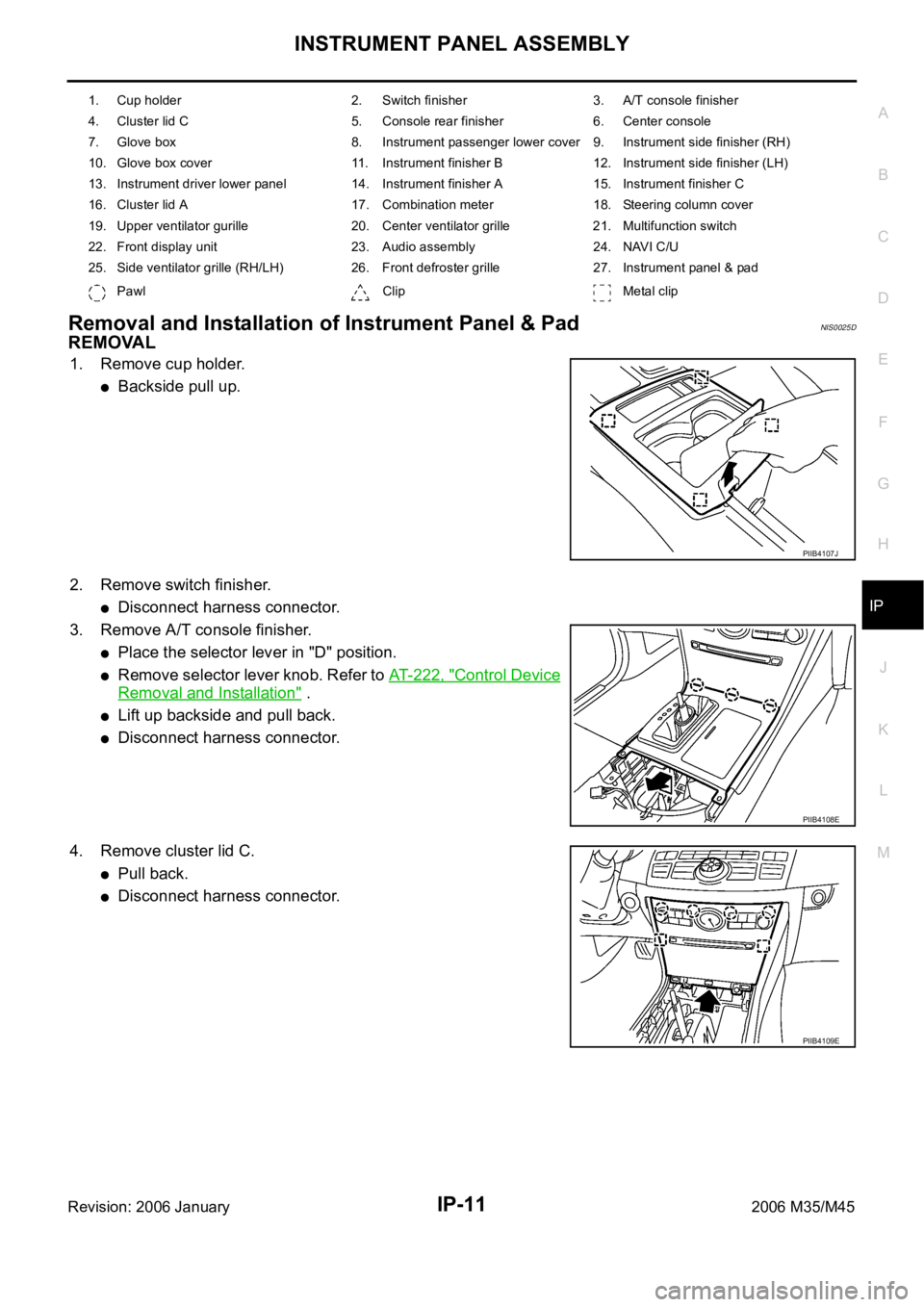
INSTRUMENT PANEL ASSEMBLY
IP-11
C
D
E
F
G
H
J
K
L
MA
B
IP
Revision: 2006 January2006 M35/M45
Removal and Installation of Instrument Panel & PadNIS0025D
REMOVAL
1. Remove cup holder.
Backside pull up.
2. Remove switch finisher.
Disconnect harness connector.
3. Remove A/T console finisher.
Place the selector lever in "D" position.
Remove selector lever knob. Refer to AT- 2 2 2 , "Control Device
Removal and Installation" .
Lift up backside and pull back.
Disconnect harness connector.
4. Remove cluster lid C.
Pull back.
Disconnect harness connector.
1. Cup holder 2. Switch finisher 3. A/T console finisher
4. Cluster lid C 5. Console rear finisher 6. Center console
7. Glove box 8. Instrument passenger lower cover 9. Instrument side finisher (RH)
10. Glove box cover 11. Instrument finisher B 12. Instrument side finisher (LH)
13. Instrument driver lower panel 14. Instrument finisher A 15. Instrument finisher C
16. Cluster lid A 17. Combination meter 18. Steering column cover
19. Upper ventilator gurille 20. Center ventilator grille 21. Multifunction switch
22. Front display unit 23. Audio assembly 24. NAVI C/U
25. Side ventilator grille (RH/LH) 26. Front defroster grille 27. Instrument panel & pad
Pawl Clip Metal clip
PIIB4107J
PIIB4108E
PIIB4109E
Page 3662 of 5621

INSTRUMENT PANEL ASSEMBLY
IP-13
C
D
E
F
G
H
J
K
L
MA
B
IP
Revision: 2006 January2006 M35/M45
13. Remove instrument driver lower panel.
Remove hood opener mounting bolt. Refer to BL-18,
"Removal and Installation of Hood Lock Control" .
Pull back.
Disconnect harness connector.
14. Remove instrument finisher A.
Insert a remover into upper space.
15. Remove instrument finisher C.
Insert a remover into upper space
16. Remove cluster lid A
Pull back.
17. Remove combination meter. Refer to DI-27, "
Removal and Installation of Combination Meter" .
18. Remove steering column cover with power tool.
19. Remove upper ventilator grille.Refer to ATC-144, "
DUCTS AND GRILLES" .
PIIB4112E
PIIB4113E
PIIB4114E
PIIB6503E
Page 4430 of 5621
LT-3
C
D
E
F
G
H
I
J
L
MA
B
LT
Revision: 2006 January2006 M35/M45 OUTLINE ...........................................................136
AFS OPERATION .............................................137
HEADLAMP AUTO AIMING OPERATION ........139
CAN COMMUNICATION SYSTEM DESCRIP-
TION ..................................................................139
CAN COMMUNICATION UNIT .........................139
Component Parts Description ..............................140
AFS CONTROL UNIT .......................................140
SWIVEL ACTUATOR ........................................140
AIMING MOTOR ...............................................140
AFS SWITCH ....................................................141
HEIGHT SENSOR ............................................141
STEERING ANGLE SENSOR ..........................141
IPDM E/R ..........................................................141
ECM ..................................................................141
TCM ..................................................................141
UNIFIED METER AND A/C AMP. .....................141
COMBINATION METER ...................................141
Schematic ............................................................142
Wiring Diagram — AFS — ...................................143
Terminals and Reference Values for AFS Control
Unit .......................................................................149
How to Proceed with Trouble Diagnosis ..............151
Preliminary Check ................................................151
CONSULT-II Function (ADAPTIVE LIGHT) ..........152
CONSULT-II BASIC OPERATION .....................152
WORK SUPPORT (STEERING ANGLE SEN-
SOR ADJUSTMENT) ........................................153
WORK SUPPORT (LEVELIZER ADJUSTMENT)
.153
SELF-DIAG RESULTS ......................................154
DATA MONITOR ...............................................158
ACTIVE TEST ...................................................160
Symptom Chart ....................................................161
DTC B2503 SWIVEL ACTUATOR RH .................162
DTC B2504 SWIVEL ACTUATOR LH ..................168
DTC B2514 HI SEN UNUSUAL RR .....................174
DTC B2521 ECU CIRC ........................................178
AFS Operation Check (Function Test) .................181
Auto Aiming Operation Check (Function Test) .....183
AFS Switch Does Not Operate .............................185
Auto Aiming Does Not Operate (Check Aiming
Motor System Circuit) ..........................................
.187
AFS OFF Indicator Does Not Operate .................190
Removal and Installation of Steering Angle Sensor .190
Removal and Installation of Front Combination
Lamp ....................................................................190
Removal and Installation of AFS Control Unit ......191
REMOVAL ........................................................
.191
INSTALLATION .................................................191
Removal and Installation of AFS Switch ..............191
REMOVAL ........................................................
.191
INSTALLATION .................................................191
Removal and Installation of Height Sensor ..........192
REMOVAL ........................................................
.192
INSTALLATION .................................................192
FRONT FOG LAMP ................................................193
Component Parts and Harness Connector Location .193
System Description ..............................................193OUTLINE ...........................................................194
COMBINATION SWITCH READING FUNCTION .195
EXTERIOR LAMP BATTERY SAVER CONTROL .195
CAN Communication System Description ............195
CAN Communication Unit .....................................195
Schematic .............................................................196
Wiring Diagram — F/FOG — ................................197
Terminals and Reference Values for BCM ............201
Terminals and Reference Values for IPDM E/R ....202
How to Perform Trouble Diagnoses .....................202
Preliminary Check ................................................202
CHECK POWER SUPPLY AND GROUND CIR-
CUIT ..................................................................202
CONSULT-II Functions (BCM) ..............................203
CONSULT-II Functions (IPDM E/R) ......................203
Front Fog Lamps Do Not Illuminate (Both Sides) . 204
Front Fog Lamp Does Not Illuminate (One Side) . 207
Front Fog Lamps Do Not Turn OFF ......................208
Aiming Adjustment ................................................209
Bulb Replacement ................................................210
Removal and Installation ......................................210
REMOVAL ........................................................
.210
INSTALLATION .................................................210
TURN SIGNAL AND HAZARD WARNING LAMPS .211
Component Parts and Harness Connector Location .211
System Description ...............................................211
TURN SIGNAL OPERATION ............................211
HAZARD LAMP OPERATION ...........................212
COMBINATION SWITCH READING FUNCTION .213
CAN Communication System Description ............213
CAN Communication Unit .....................................213
Schematic .............................................................214
Wiring Diagram — TURN — .................................215
Terminals and Reference Values for BCM ............219
How to Perform Trouble Diagnoses .....................220
Preliminary Check ................................................221
CHECK POWER SUPPLY AND GROUND CIR-
CUIT ..................................................................221
CONSULT-II Functions (BCM) ..............................223
CONSULT-II BASIC OPERATION .....................223
DATA MONITOR ...............................................224
ACTIVE TEST ...................................................224
Turn Signal Lamp Does Not Operate ...................225
H a z a r d W a r n i n g L a m p D o e s N o t O p e r a t e B u t T u r n
Signal Lamp Operate ............................................227
Turn Signal Indicator Lamp Does Not Operate ....228
Bulb Replacement/Removal and Installation of Side
Turn Signal Lamp .................................................229
REMOVAL ........................................................
.229
INSTALLATION .................................................229
Bulb Replacement (Front Turn Signal Lamp) .......229
Bulb Replacement (Rear Turn Signal Lamp) ........229
Removal and Installation of Front Turn Signal Lamp .229
Removal and Installation of Rear Turn Signal Lamp .229
LIGHTING AND TURN SIGNAL SWITCH ..............230
Removal and Installation ......................................230
REMOVAL ........................................................
.230
INSTALLATION .................................................230
Switch Circuit Inspection ......................................230