change time INFINITI M35 2006 Factory Service Manual
[x] Cancel search | Manufacturer: INFINITI, Model Year: 2006, Model line: M35, Model: INFINITI M35 2006Pages: 5621, PDF Size: 65.56 MB
Page 5445 of 5621
![INFINITI M35 2006 Factory Service Manual STC-30
[RAS]
TROUBLE DIAGNOSIS
Revision: 2006 January2006 M35/M45
DATA MONITOR MODE
Operation Procedure
1. Perform “CONSULT-II Start Procedure”. Refer to GI-39, "CONSULT-II Start Procedure" INFINITI M35 2006 Factory Service Manual STC-30
[RAS]
TROUBLE DIAGNOSIS
Revision: 2006 January2006 M35/M45
DATA MONITOR MODE
Operation Procedure
1. Perform “CONSULT-II Start Procedure”. Refer to GI-39, "CONSULT-II Start Procedure"](/img/42/57023/w960_57023-5444.png)
STC-30
[RAS]
TROUBLE DIAGNOSIS
Revision: 2006 January2006 M35/M45
DATA MONITOR MODE
Operation Procedure
1. Perform “CONSULT-II Start Procedure”. Refer to GI-39, "CONSULT-II Start Procedure" .
2. Touch “DATA MONITOR”.
3. Select from “SELECT MONITOR ITEM”, screen of data monitor is displayed.
NOTE:
When malfunction is detected, CONSULT-II performs REAL-TIME DIAGNOSIS. Also, any malfunction
detected while in this mode will be displayed in real time.
Display Item List
ACTIVE TEST MODE
Operation Procedure
1. Perform “CONSULT-II Start Procedure”. Refer to GI-39, "CONSULT-II Start Procedure" .
2. When turning the steering wheel right or left, the rear wheel turns in the same direction. If the steering
wheel is not turned, the rear wheel turns left and right 5 times.
RAS CONTROL UNIT PART NUMBER
1. Perform “CONSULT-II Start Procedure”. Refer to GI-39, "CONSULT-II Start Procedure" .
2. The part number described on RAS control unit sticker is displayed.
Item (Display or Unit) Remarks
VHCL SPEED SE (km/h) Vehicle speed received via CAN communication is displayed.
STEERING ANG (
) Steering angle received via CAN communication is displayed.
ENGINE SPEED (rpm) Engine speed received via CAN communication is displayed.
POWER STR SOL (A)Power steering solenoid controlling current that RAS control unit outputs is dis-
played.
RR ST ANG_MAI (V) Rear wheel steering angle main sensor output voltage is displayed.
RR ST ANG_SUB (V) Rear wheel angle sub sensor output voltage is displayed.
RR ST ANG_ VOL (V)Voltage supplied from RAS control unit to rear wheel steering angle sensor is
displayed.
C/U VOLTAGE (V) Voltage supplied to RAS control unit is displayed.
MOTOR VOLTAGE (V) Voltage supplied from RAS control unit to RAS motor is displayed.
MOTOR CURRENT (A) RAS motor relay controlling current that RAS control unit outputs is displayed.
MOTOR CRNT OPE (A) Current commanded value to RAS motor is displayed.
RR ANG OPE (
) Angle commanded value to rear wheel steering angle sensor is displayed.
STOP LAMP SW (ON/OFF) Condition of stop lamp switch ON/OFF is displayed.
HICAS RELAY (ON/OFF) RAS motor relay ON/OFF condition is displayed.
FAILSAFE (ON/OFF) Fail-safe ON/OFF condition is displayed.
WARNING LAMP (ON/OFF) RAS warning lamp operating condition is displayed.
STEERING ANG RR ST ANG_MAI RR ST ANG_SUB MOTOR CURRENT
0
(Neutral) 2.4 V 2.4 V No output (Approx. 0 A)
R 90
Approx. 4.4 V Approx. 4.4 V
Output (change)
L 90
Approx. 0.4 V Approx. 0.4 V
Page 5475 of 5621
TF-10
AWD SYSTEM
Revision: 2006 January2006 M35/M45
AWD SYSTEMPFP:41650
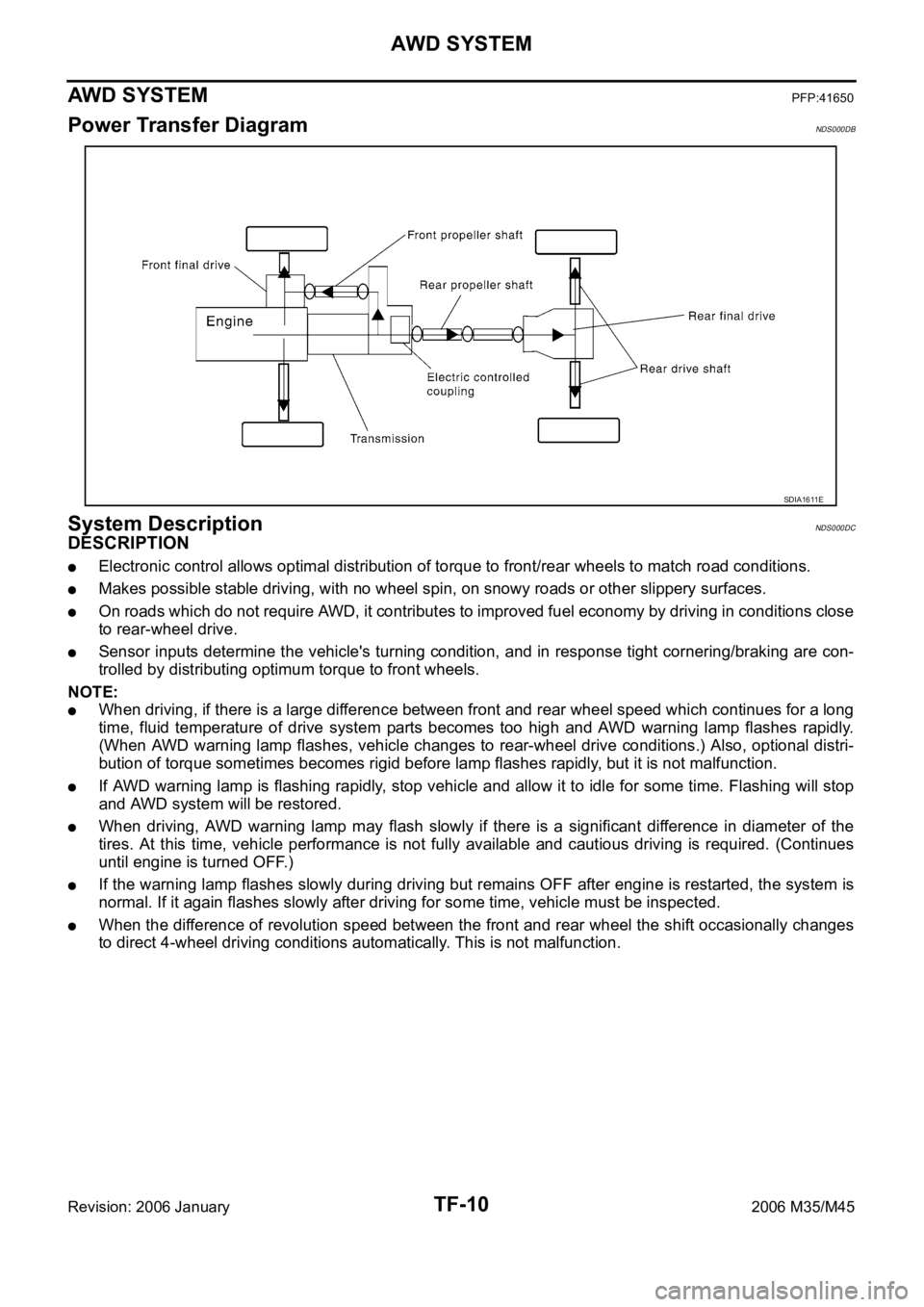
Power Transfer DiagramNDS000DB
System DescriptionNDS000DC
DESCRIPTION
Electronic control allows optimal distribution of torque to front/rear wheels to match road conditions.
Makes possible stable driving, with no wheel spin, on snowy roads or other slippery surfaces.
On roads which do not require AWD, it contributes to improved fuel economy by driving in conditions close
to rear-wheel drive.
Sensor inputs determine the vehicle's turning condition, and in response tight cornering/braking are con-
trolled by distributing optimum torque to front wheels.
NOTE:
When driving, if there is a large difference between front and rear wheel speed which continues for a long
time, fluid temperature of drive system parts becomes too high and AWD warning lamp flashes rapidly.
(When AWD warning lamp flashes, vehicle changes to rear-wheel drive conditions.) Also, optional distri-
bution of torque sometimes becomes rigid before lamp flashes rapidly, but it is not malfunction.
If AWD warning lamp is flashing rapidly, stop vehicle and allow it to idle for some time. Flashing will stop
and AWD system will be restored.
When driving, AWD warning lamp may flash slowly if there is a significant difference in diameter of the
tires. At this time, vehicle performance is not fully available and cautious driving is required. (Continues
until engine is turned OFF.)
If the warning lamp flashes slowly during driving but remains OFF after engine is restarted, the system is
normal. If it again flashes slowly after driving for some time, vehicle must be inspected.
When the difference of revolution speed between the front and rear wheel the shift occasionally changes
to direct 4-wheel driving conditions automatically. This is not malfunction.
SDIA1611E
Page 5477 of 5621
TF-12
AWD SYSTEM
Revision: 2006 January2006 M35/M45
AWD WARNING LAMP
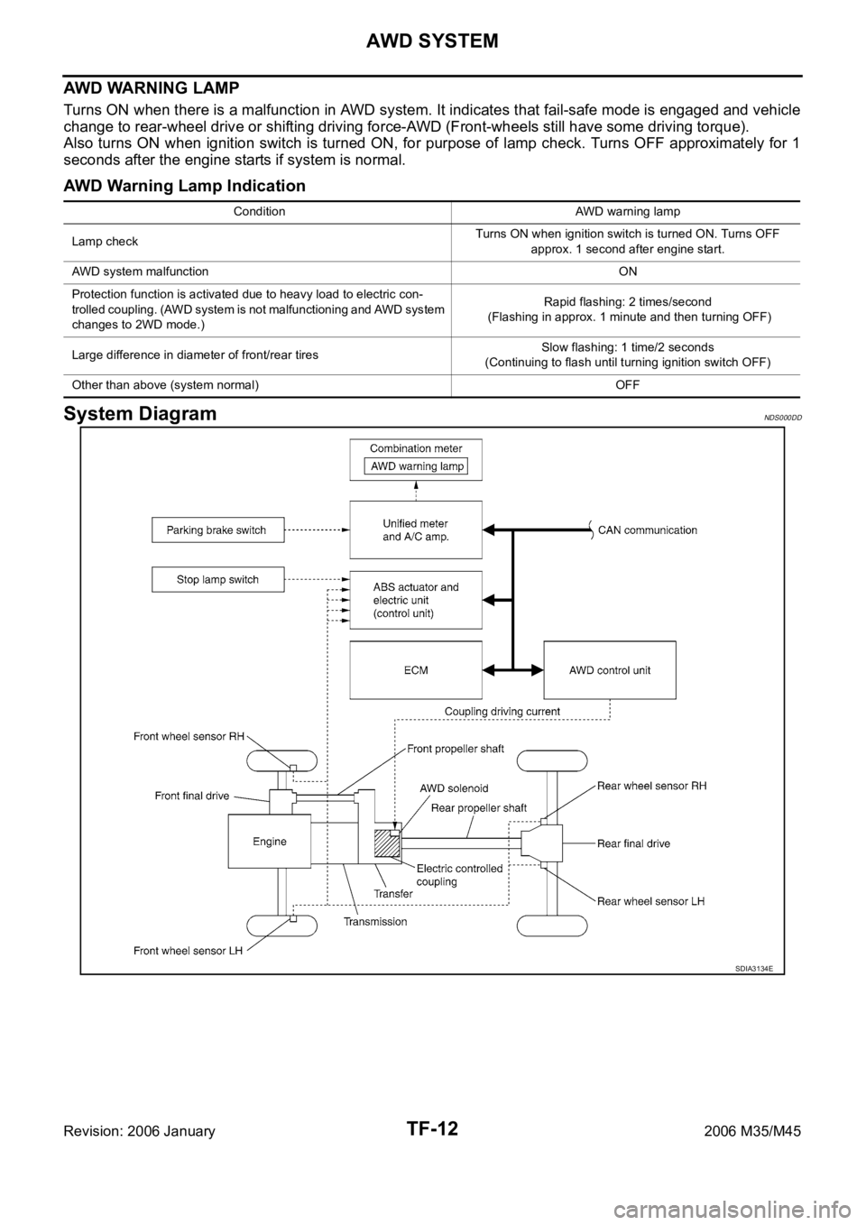
Turns ON when there is a malfunction in AWD system. It indicates that fail-safe mode is engaged and vehicle
change to rear-wheel drive or shifting driving force-AWD (Front-wheels still have some driving torque).
Also turns ON when ignition switch is turned ON, for purpose of lamp check. Turns OFF approximately for 1
seconds after the engine starts if system is normal.
AWD Warning Lamp Indication
System DiagramNDS000DD
Condition AWD warning lamp
Lamp checkTurns ON when ignition switch is turned ON. Turns OFF
approx. 1 second after engine start.
AWD system malfunctionON
Protection function is activated due to heavy load to electric con-
trolled coupling. (AWD system is not malfunctioning and AWD system
changes to 2WD mode.)Rapid flashing: 2 times/second
(Flashing in approx. 1 minute and then turning OFF)
Large difference in diameter of front/rear tiresSlow flashing: 1 time/2 seconds
(Continuing to flash until turning ignition switch OFF)
Other than above (system normal) OFF
SDIA3134E
Page 5490 of 5621

TROUBLE DIAGNOSIS
TF-25
C
E
F
G
H
I
J
K
L
MA
B
TF
Revision: 2006 January2006 M35/M45
ACTIVE TEST MODE
Description
Use this mode to determine and identify the details of a malfunction based on self-diagnostic results or data
monitor. AWD control unit gives drive signal to actuator with receiving command from CONSULT-II to check
operation of actuator.
Test Item
CAUTION:
Do not continuously energize for a long time.
AWD CONTROL UNIT PART NUMBER
Ignore the AWD control unit part number displayed in the “ECU PART NUMBER”.
Refer to parts catalog to order the AWD control unit.
Test item Condition Description
ETS S/V
(Detects AWD solenoid)
Vehicle stopped
Engine running
No DTC detected
Change command current value to AWD solenoid, and then change driv-
ing mode. (Monitor value is normal if it is within approximately
10% of
command value.)
Qu: Increase current value in increments of 0.20A
Qd: Decrease current value in increments of 0.20A
UP: Increase current value in increments of 0.02A
DOWN: Decrease current value in increments of 0.02A
Page 5575 of 5621
WW-8
FRONT WIPER AND WASHER SYSTEM
Revision: 2006 January2006 M35/M45
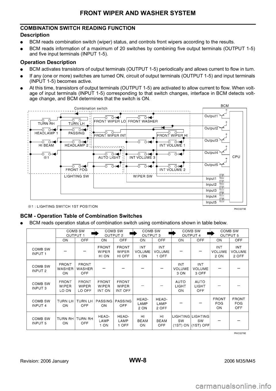
COMBINATION SWITCH READING FUNCTION
Description
BCM reads combination switch (wiper) status, and controls front wipers according to the results.
BCM reads information of a maximum of 20 switches by combining five output terminals (OUTPUT 1-5)
and five input terminals (INPUT 1-5).
Operation Description
BCM activates transistors of output terminals (OUTPUT 1-5) periodically and allows current to flow in turn.
If any (one or more) switches are turned ON, circuit of output terminals (OUTPUT 1-5) and input terminals
(INPUT 1-5) becomes active.
At this time, transistors of output terminals (OUTPUT 1-5) are activated to allow current to flow. When volt-
age of input terminals (INPUT 1-5) corresponding to that switch changes, interface in BCM detects volt-
age change, and BCM determines that the switch is ON.
BCM - Operation Table of Combination Switches
BCM reads operation status of combination switch using combinations shown in table below.
PKIC0270E
PKIC0276E
Page 5576 of 5621
FRONT WIPER AND WASHER SYSTEM
WW-9
C
D
E
F
G
H
I
J
L
MA
B
WW
Revision: 2006 January2006 M35/M45
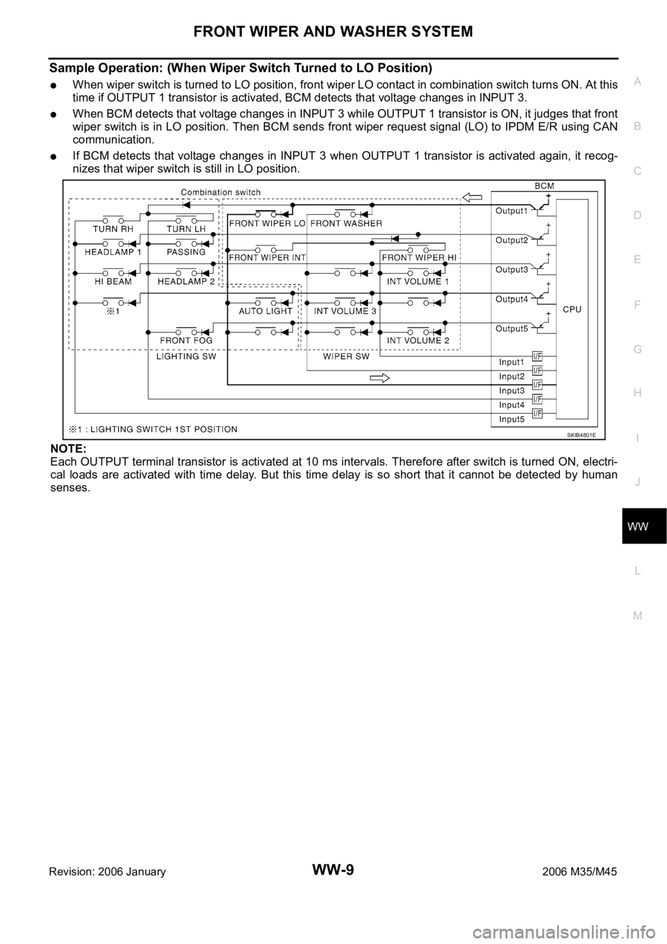
Sample Operation: (When Wiper Switch Turned to LO Position)
When wiper switch is turned to LO position, front wiper LO contact in combination switch turns ON. At this
time if OUTPUT 1 transistor is activated, BCM detects that voltage changes in INPUT 3.
When BCM detects that voltage changes in INPUT 3 while OUTPUT 1 transistor is ON, it judges that front
wiper switch is in LO position. Then BCM sends front wiper request signal (LO) to IPDM E/R using CAN
communication.
If BCM detects that voltage changes in INPUT 3 when OUTPUT 1 transistor is activated again, it recog-
nizes that wiper switch is still in LO position.
NOTE:
Each OUTPUT terminal transistor is activated at 10 ms intervals. Therefore after switch is turned ON, electri-
cal loads are activated with time delay. But this time delay is so short that it cannot be detected by human
senses.
SKIB4801E
Page 5590 of 5621
FRONT WIPER AND WASHER SYSTEM
WW-23
C
D
E
F
G
H
I
J
L
MA
B
WW
Revision: 2006 January2006 M35/M45
CONSULT-II Functions (BCM)NKS003WL
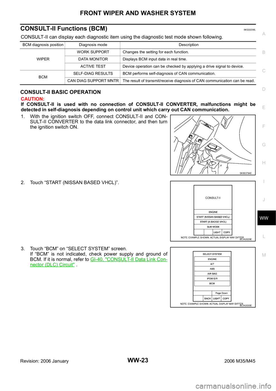
CONSULT-II can display each diagnostic item using the diagnostic test mode shown following.
CONSULT-II BASIC OPERATION
CAUTION:
If CONSULT-II is used with no connection of CONSULT-II CONVERTER, malfunctions might be
detected in self-diagnosis depending on control unit which carry out CAN communication.
1. With the ignition switch OFF, connect CONSULT-II and CON-
SULT-II CONVERTER to the data link connector, and then turn
the ignition switch ON.
2. Touch “START (NISSAN BASED VHCL)”.
3. Touch “BCM” on “SELECT SYSTEM” screen.
If “BCM” is not indicated, check power supply and ground of
BCM. If it is normal, refer to GI-40, "
CONSULT-II Data Link Con-
nector (DLC) Circuit" .
BCM diagnosis position Diagnosis mode Description
WIPERWORK SUPPORT Changes the setting for each function.
DATA MONITOR Displays BCM input data in real time.
ACTIVE TEST Device operation can be checked by applying a drive signal to device.
BCMSELF-DIAG RESULTS BCM performs self-diagnosis of CAN communication.
CAN DIAG SUPPORT MNTR The result of transmit/receive diagnosis of CAN communication can be read.
SKIB3794E
BCIA0029E
BCIA0030E
Page 5591 of 5621

WW-24
FRONT WIPER AND WASHER SYSTEM
Revision: 2006 January2006 M35/M45
4. Touch “WIPER”.
WORK SUPPORT
Operation Procedure
1. Touch “WIPER” on “SELECT TEST ITEM” screen.
2. Touch “WORK SUPPORT” on “SELECT DIAG MODE” screen.
3. Touch “WIPER SPEED SETTING” on “SELECT WORK ITEM” screen.
4. Touch “START”.
5. Touch “CHANGE SETT”.
6. The setting will be changed and“ CURRENT SETTING” will be displayed.
7. Touch “END”.
Work Support Setting Item
NOTE:
Factory setting
DATA MONITOR
Operation Procedure
1. Touch “WIPER” on the “SELECT TEST ITEM” screen.
2. Touch “DATA MONITOR” on “SELECT DIAG MODE” screen.
3. Touch either “ALL SIGNALS” or “SELECTION FROM MENU” on “SELECT MONITOR ITEM” screen.
4. When “SELECTION FROM MENU” is selected, touch items to be monitored. If “ALL SIGNALS” is
selected, all items will be monitored.
5. Touch “START”.
6. Touch “RECORDING START” while monitoring to record the status of the item being monitored. To stop
recording, touch “RECORDING STOP”.
SKIB4803E
Item Description CONSULT-II
WIPER SPEED SETTINGWhen wiper switch is at INTERMITTENT, front wiper intermittent time can be selected
according to vehicle speed.
ONNOTE (Operated)/OFF (Not operated)ON/OFF
ALL SIGNALS Monitors all the signals.
SELECTION FROM MENU Selects items and monitors them.