stall INFINITI M35 2006 Factory Service Manual
[x] Cancel search | Manufacturer: INFINITI, Model Year: 2006, Model line: M35, Model: INFINITI M35 2006Pages: 5621, PDF Size: 65.56 MB
Page 5517 of 5621

TF-52
TRANSFER ASSEMBLY
Revision: 2006 January2006 M35/M45
ASSEMBLY
Front Drive Shaft and Drive Chain
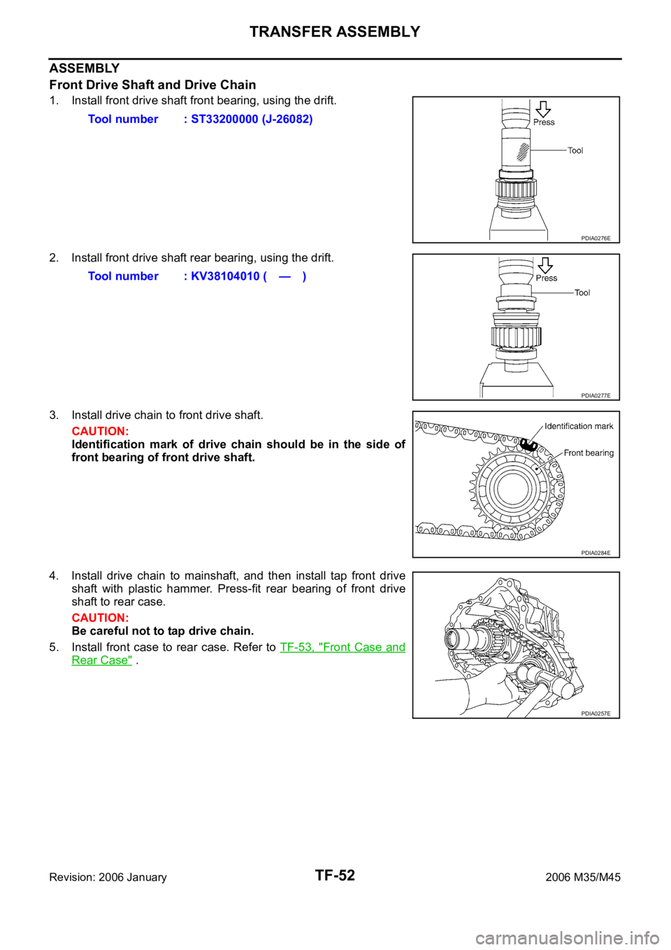
1. Install front drive shaft front bearing, using the drift.
2. Install front drive shaft rear bearing, using the drift.
3. Install drive chain to front drive shaft.
CAUTION:
Identification mark of drive chain should be in the side of
front bearing of front drive shaft.
4. Install drive chain to mainshaft, and then install tap front drive
shaft with plastic hammer. Press-fit rear bearing of front drive
shaft to rear case.
CAUTION:
Be careful not to tap drive chain.
5. Install front case to rear case. Refer to TF-53, "
Front Case and
Rear Case" . Tool number : ST33200000 (J-26082)
PDIA0276E
Tool number : KV38104010 ( — )
PDIA0277E
PDIA0284E
PDIA0257E
Page 5518 of 5621

TRANSFER ASSEMBLY
TF-53
C
E
F
G
H
I
J
K
L
MA
B
TF
Revision: 2006 January2006 M35/M45
Mainshaft Assembly
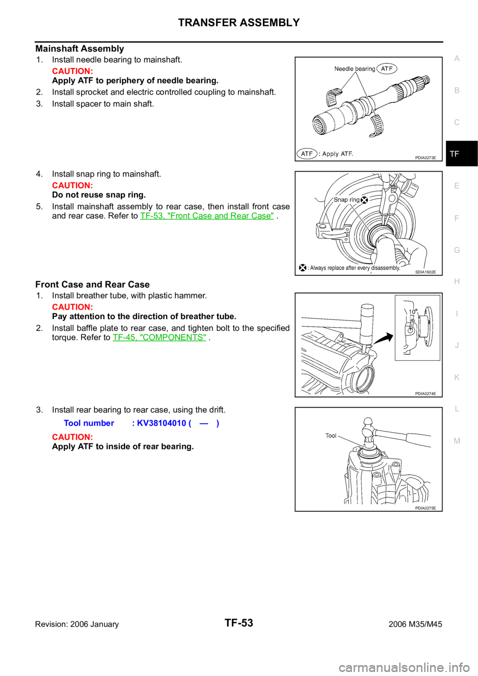
1. Install needle bearing to mainshaft.
CAUTION:
Apply ATF to periphery of needle bearing.
2. Install sprocket and electric controlled coupling to mainshaft.
3. Install spacer to main shaft.
4. Install snap ring to mainshaft.
CAUTION:
Do not reuse snap ring.
5. Install mainshaft assembly to rear case, then install front case
and rear case. Refer to TF-53, "
Front Case and Rear Case" .
Front Case and Rear Case
1. Install breather tube, with plastic hammer.
CAUTION:
Pay attention to the direction of breather tube.
2. Install baffle plate to rear case, and tighten bolt to the specified
torque. Refer to TF-45, "
COMPONENTS" .
3. Install rear bearing to rear case, using the drift.
CAUTION:
Apply ATF to inside of rear bearing.
PDIA0273E
SDIA1602E
PDIA0274E
Tool number : KV38104010 ( — )
PDIA0275E
Page 5519 of 5621

TF-54
TRANSFER ASSEMBLY
Revision: 2006 January2006 M35/M45
4. Install snap ring to rear case.
CAUTION:
Do not reuse snap ring.
5. Install mainshaft assembly to rear case, using the drift.
CAUTION:
ATF should be applied to contact surface of mainshaft and
rear bearing.
6. Install O-ring to transfer assembly harness connector.
CAUTION:
Do not reuse O-ring.
Apply ATF to O-ring.
7. Install transfer assembly harness connector into rear case.
8. Install retainer to transfer assembly harness connector.
9. Set temperature sensor and tighten bolt to the specified torque.
Refer to TF-45, "
COMPONENTS" .
10. Hold electric controlled coupling harness with oil cover hold
plate, install oil cover to rear case, and tighten bolt to the speci-
fied torque. Refer to TF-45, "
COMPONENTS" .
CAUTION:
The harness should be guided by a cut portion.
PDIA0263E
Tool number : ST35321000 ( — )
SDIA2368E
SDIA1597E
SDIA2404E
Page 5520 of 5621

TRANSFER ASSEMBLY
TF-55
C
E
F
G
H
I
J
K
L
MA
B
TF
Revision: 2006 January2006 M35/M45
11. Install oil gutter to rear case.
CAUTION:
The tip of oil gutter should be put into rear case groove.
12. Install drive chain to front drive shaft.
CAUTION:
Identification mark of drive chain should be in the side of
front bearing of front drive shaft.
13. Install drive chain to mainshaft, and then install tap front drive
shaft with plastic hammer. Press-fit rear bearing of front drive
shaft to rear case.
CAUTION:
Be careful not to tap drive chain.
14. Install mainshaft bearing to front case, using the drift.
15. Install snap ring to front case.
CAUTION:
Do not reuse snap ring.
PDIA0261E
PDIA0284E
PDIA0257E
Tool number : ST30621000 (J-25742-5)
PDIA0283E
PDIA0267E
Page 5521 of 5621

TF-56
TRANSFER ASSEMBLY
Revision: 2006 January2006 M35/M45
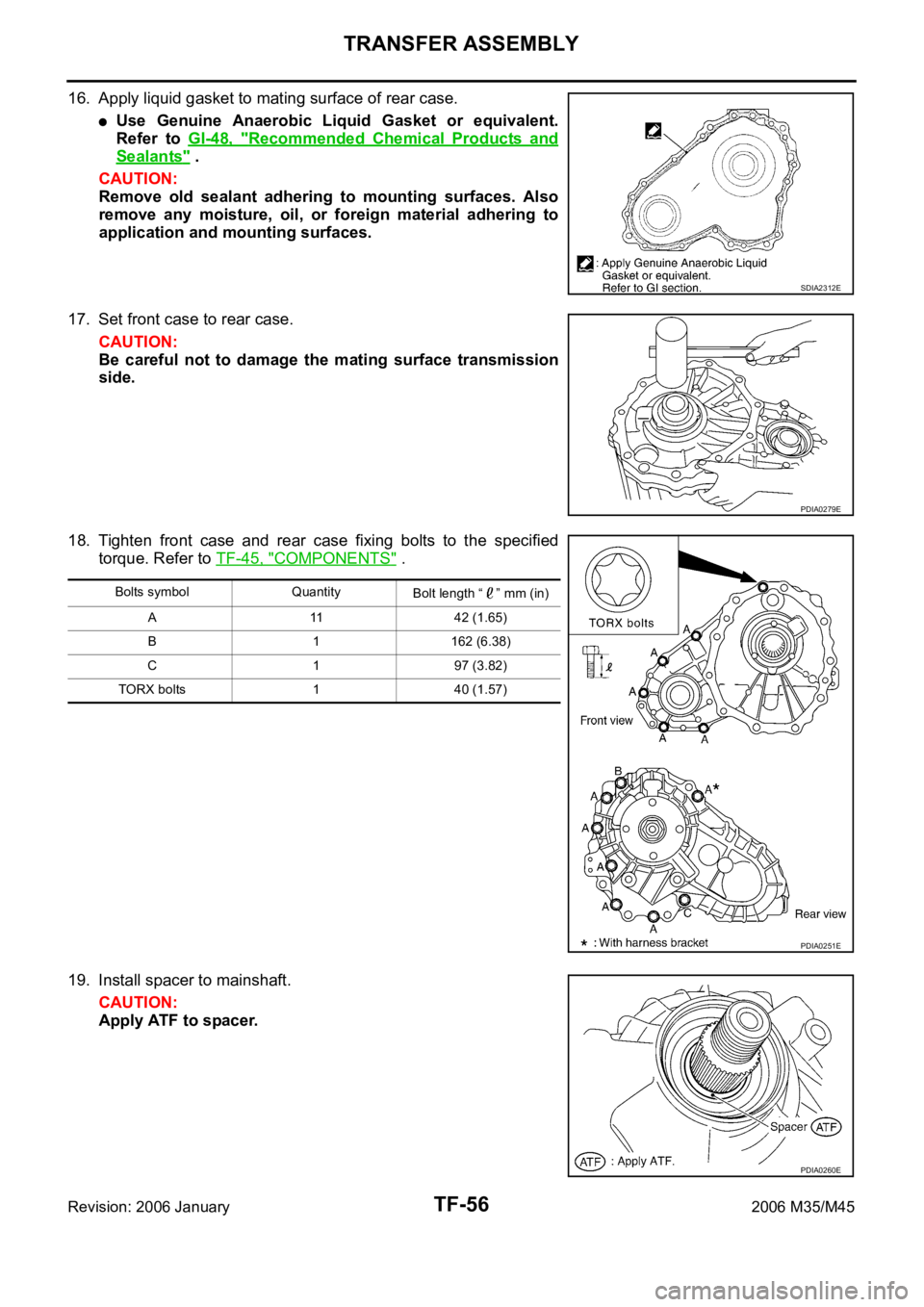
16. Apply liquid gasket to mating surface of rear case.
Use Genuine Anaerobic Liquid Gasket or equivalent.
Refer to GI-48, "
Recommended Chemical Products and
Sealants" .
CAUTION:
Remove old sealant adhering to mounting surfaces. Also
remove any moisture, oil, or foreign material adhering to
application and mounting surfaces.
17. Set front case to rear case.
CAUTION:
Be careful not to damage the mating surface transmission
side.
18. Tighten front case and rear case fixing bolts to the specified
torque. Refer to TF-45, "
COMPONENTS" .
19. Install spacer to mainshaft.
CAUTION:
Apply ATF to spacer.
SDIA2312E
PDIA0279E
Bolts symbol Quantity
Bolt length “ ” mm (in)
A 11 42 (1.65)
B 1 162 (6.38)
C 1 97 (3.82)
TORX bolts 1 40 (1.57)
PDIA0251E
PDIA0260E
Page 5522 of 5621

TRANSFER ASSEMBLY
TF-57
C
E
F
G
H
I
J
K
L
MA
B
TF
Revision: 2006 January2006 M35/M45
20. Install rear oil seal to rear case, using the drifts.
CAUTION:
Do not reuse rear oil seal.
Apply ATF to rear oil seal.
When installing, do not incline rear oil seal.
21. Install companion flange while align the matching mark of main-
shaft with the mark of companion flange.
22. Tighten self-lock nut to the specified torque, with flange wrench.
Refer to TF-45, "
COMPONENTS" .
CAUTION:
Do not reuse self-lock nut.
23. Install mainshaft oil seal until it is flush with end face of front
case, using the drift.
CAUTION:
Do not reuse mainshaft oil seal.
Apply ATF to mainshaft oil seal.
When installing, do not incline mainshaft oil seal.
24. Install front oil seal until it is flush with end face of front case,
using the drift.
CAUTION:
Do not reuse front oil seal.
Apply ATF to front oil seal.
When installing, do not incline front oil seal.
25. Apply sealant to threads of drain plug. Then install it to rear case
and tighten to the specified torque. Refer to TF-45, "
COMPO-
NENTS" . Dimension A : 6.7 - 7.3 mm (0.264 - 0.287 in)
Tool number A: ST30720000 (J-25405)
B: KV40104830 ( — )
PDIA0281E
SDIA2378E
SDIA2369E
Tool number : ST30720000 (J-25405)
PDIA0282E
Tool number : ST27862000 ( — )
PDIA0287E
Page 5523 of 5621

TF-58
TRANSFER ASSEMBLY
Revision: 2006 January2006 M35/M45
Use Genuine Silicone RTV or equivalent. Refer to GI-48, "Recommended Chemical Products and
Sealants" .
CAUTION:
Remove old sealant and oil adhering to threads.
26. Set gasket to filler plug. Install it to rear case and tighten to the specified torque. Refer to TF-45, "
COM-
PONENTS" .
CAUTION:
Do not reuse gasket.
After oil is filled, tighten filler plug to specified torque.
Page 5527 of 5621

WT-2Revision: 2006 January2006 M35/M45 MALFUNCTION CODE NO. 52 ........................... 34
Inspection 8: CAN Communication System Mal-
function ................................................................... 34
TROUBLE DIAGNOSIS FOR SYMPTOMS .............. 35
Inspection 1: Warning Lamp Does Not Come On
When Ignition Switch Is Turned On ........................ 35
Inspection 2: Warning Lamp Stays On When Ignition
Switch Is Turned On ............................................ ... 36
Inspection 3: Warning Lamp Blinks When Ignition
Switch Is Turned On ............................................ ... 37
Inspection 4: Turn Signal Lamp Blinks When Ignition
Switch Is Turned On ............................................ ... 37
Inspection 5: ID Registration Can Not Be Completed ... 38REMOVAL AND INSTALLATION .............................. 39
Transmitter .............................................................. 39
REMOVAL ............................................................ 39
INSTALLATION .................................................... 39
Low Tire Pressure Warning Control Unit ................. 40
REMOVAL ............................................................ 40
INSTALLATION .................................................... 40
Receiver .................................................................. 40
REMOVAL ............................................................ 40
INSTALLATION .................................................... 40
SERVICE DATA AND SPECIFICATIONS (SDS) ...... 41
Road Wheel ............................................................ 41
Tire .......................................................................... 41
Page 5530 of 5621

NOISE, VIBRATION AND HARSHNESS (NVH) TROUBLESHOOTING
WT-5
C
D
F
G
H
I
J
K
L
MA
B
WT
Revision: 2006 January2006 M35/M45
NOISE, VIBRATION AND HARSHNESS (NVH) TROUBLESHOOTINGPFP:00003
NVH Troubleshooting ChartNES000JN
Use chart below to help you find the cause of the symptom. If necessary, repair or replace these parts.
: ApplicableReference page
FAX-5
, FSU-6WT-6WT-7WT-41WT-8—
—
WT-41
NVH in PR section.
NVH in RFD section.
NVH in FAX and FSU sections.
NVH in RAX and RSU sections.
Refer to TIRES in this chart.
Refer to ROAD WHEEL in this chart.
NVH in FAX, RAX section.
NVH in BR section.
NVH in PS section.
Possible cause and SUSPECTED PARTS
Improper installation, looseness
Out-of-round
Imbalance
Incorrect tire pressure
Uneven tire wear
Deformation or damage
Non-uniformity
Incorrect tire size
PROPELLER SHAFT
DIFFERENTIAL
FRONT AXLE AND FRONT SUSPENSION
REAR AXLE AND REAR SUSPENSION
TIRES
ROAD WHEELS
DRIVE SHAFT
BRAKE
STEERING
SymptomTIRESNoise
Shake
Vibration
Shimmy
Judder
Poor quality ride or
handling
ROAD
WHEELNoiseShake
Shimmy, Judder
Poor quality ride or
handling
Page 5532 of 5621

ROAD WHEEL TIRE ASSEMBLY
WT-7
C
D
F
G
H
I
J
K
L
MA
B
WT
Revision: 2006 January2006 M35/M45
ROAD WHEEL TIRE ASSEMBLYPFP:40300
Balancing Wheels (Bonding Weight Type)NES000JP
REMOVAL
1. Using releasing agent, remove double-faced adhesive tape from the road wheel.
CAUTION:
Be careful not to scratch the road wheel during removal.
After removing double-faced adhesive tape, wipe clean traces of releasing agent from the road
wheel.
WHEEL BALANCE ADJUSTMENT
If a tire balance machine has adhesion balance weight mode settings and drive-in weight mode setting, select
and adjust a drive-in weight mode suitable for road wheels.
1. Set road wheel on wheel balancer using the center hole as a guide. Start the tire balance machine.
2. When inner and outer unbalance values are shown on the tire balance machine indicator, multiply outer
unbalance value by 5/3 to determine balance weight that should be used. Select the outer balance weight
with a value closest to the calculated value above and install it to the designated outer position of, or at the
designated angle in relation to the road wheel.
CAUTION:
Do not install the inner balance weight before installing the outer balance weight.
Before installing the balance weight, be sure to clean the mating surface of the road wheel.
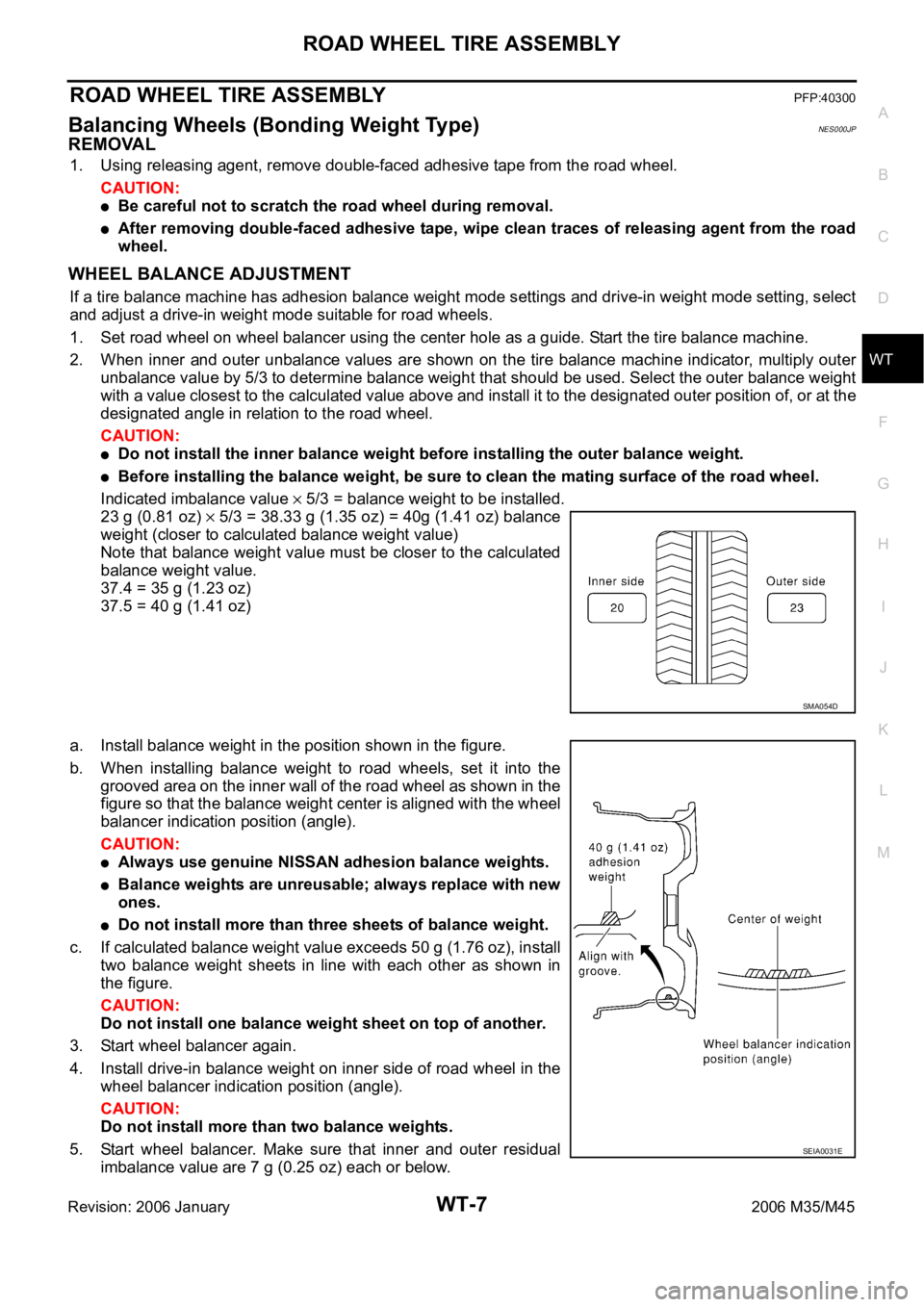
Indicated imbalance value
5/3 = balance weight to be installed.
23 g (0.81 oz)
5/3 = 38.33 g (1.35 oz) = 40g (1.41 oz) balance
weight (closer to calculated balance weight value)
Note that balance weight value must be closer to the calculated
balance weight value.
37.4 = 35 g (1.23 oz)
37.5 = 40 g (1.41 oz)
a. Install balance weight in the position shown in the figure.
b. When installing balance weight to road wheels, set it into the
grooved area on the inner wall of the road wheel as shown in the
figure so that the balance weight center is aligned with the wheel
balancer indication position (angle).
CAUTION:
Always use genuine NISSAN adhesion balance weights.
Balance weights are unreusable; always replace with new
ones.
Do not install more than three sheets of balance weight.
c. If calculated balance weight value exceeds 50 g (1.76 oz), install
two balance weight sheets in line with each other as shown in
the figure.
CAUTION:
Do not install one balance weight sheet on top of another.
3. Start wheel balancer again.
4. Install drive-in balance weight on inner side of road wheel in the
wheel balancer indication position (angle).
CAUTION:
Do not install more than two balance weights.
5. Start wheel balancer. Make sure that inner and outer residual
imbalance value are 7 g (0.25 oz) each or below.
SMA054D
SEIA0031E