headlamp INFINITI M35 2006 Factory Service Manual
[x] Cancel search | Manufacturer: INFINITI, Model Year: 2006, Model line: M35, Model: INFINITI M35 2006Pages: 5621, PDF Size: 65.56 MB
Page 4588 of 5621

ACTIVE AFS
LT-161
C
D
E
F
G
H
I
J
L
MA
B
LT
Revision: 2006 January2006 M35/M45
Symptom ChartNKS003QN
CAUTION:
The low beam headlamps performs small movements when AFS control unit detects the engine start.
This is normal with initialization of swivel actuator by AFS control unit.
SymptomAFS OFF
indicatorCausal system Reference
AFS operates, but cannot judge normal/
abnormal.
(AFS function test)NormalCheck swivel operation.LT-181, "AFS
Operation
Check (Func-
tion Test)"
Check steering angle sensor neutral point (straight-ahead
position).
Auto aiming operates, but cannot judge
normal/abnormal.
(Auto aiming function test)NormalCheck auto aiming operation.LT-183, "Auto
Aiming Opera-
tion Check
(Function
Te s t )"
Check height sensor signal value recognized by AFS con-
trol unit at unloaded vehicle position.
Check height sensor signal and aiming motor drive signal.
Neither AFS operates nor auto aiming
operates.BlinkingCheck AFS control unit self-diagnostic results. LT-154,
"SELF-DIAG
RESULTS"
Check AFS control unit power supply and ground circuit.
NOTE:
Check only when “ADAPTIVE LIGHT” is not displayed on
CONSULT-II “SELECT SYSTEM” screen.LT-151, "Pre-
liminary
Check"
AFS does not operate.
(Auto aiming operation is normal.)Blinking Check AFS control unit self-diagnostic results. LT-154,
"SELF-DIAG
RESULTS"
Illuminated Check AFS switch system circuit.LT-185, "
AFS
Switch Does
Not Operate"
Auto aiming does not operate.
(AFS operation is normal.)NormalCheck AFS control unit self-diagnostic results. LT-154,
"SELF-DIAG
RESULTS"
Check aiming motor system circuit.LT-187, "
Auto
Aiming Does
Not Operate
(Check Aiming
Motor System
Circuit)"
Auto aiming operates in the reverse way.
(Lowering vehicle height angles light
axis up.)Normal Replace AFS control unit.LT-191, "Removal and
Installation of
AFS Control
Unit"
AFS OFF indicator does not illuminate.
(AFS operation and auto aiming opera-
tion are normal.)Not
illuminatedCheck circuit between unified meter and A/C amp. and
combination meter.LT-190, "
AFS
OFF Indicator
Does Not
Operate"AFS OFF indicator blinks.
(AFS operation and auto aiming opera-
tion are normal.)BlinkingCheck receive state of AFS off indicator signal from uni-
fied meter and A/C amp.
AFS cannot be cancelled.
(AFS switch does not operate.)Normal Check AFS switch system circuit.LT-185, "AFS
Switch Does
Not Operate"
Page 4608 of 5621

ACTIVE AFS
LT-181
C
D
E
F
G
H
I
J
L
MA
B
LT
Revision: 2006 January2006 M35/M45
AFS Operation Check (Function Test)NKS003QS
1. CHECK SWIVEL ACTUATOR
1. Start engine and turn lighting switch to 2ND position.
2. Select “ADAPTIVE LIGHT” on CONSULT-II. Select “ACTIVE
TEST” on “SELECT DIAG MODE” screen.
3. Select “LOW BEAM TEST RIGHT” or “LOW BEAM TEST LEFT”
on “SELECT TEST ITEM” screen.
4. Touch “ORIGIN–FAST/SLOW” and “PEAK–FAST/SLOW”
screen.
5. Make sure of swivel operation.
OK or NG
OK >> GO TO 2.
NG >>
When interference or poor fitment is found, perform aiming adjustment. Refer to LT- 7 4 , "Aiming
Adjustment" . If it is normal, replace headlamp. Refer to LT- 1 9 0 , "Removal and Installation of
Front Combination Lamp" .
When the operation range is irregular, perform aiming adjustment. Refer to LT- 7 4 , "Aiming
Adjustment" . If it is normal, GO TO 3.
2. CHECK STEERING ANGLE SENSOR
Check “STR ANGLE SIG” in “Data Monitor” when driving straight
and steering turn 90
to right or left.
OK or NG
OK >> GO TO 3.
NG >>
When steering is out of range while driving straight, perform steering angle sensor adjustment.
Refer to BRC-6, "
Adjustment of Steering Angle Sensor Neutral Position" in “ON-VEHICLE
SERVICE”.
When the function is normal while driving straight but the displayed value is different from
actual steering position with turning to right or left, replace steering angle sensor. Refer to LT-
190, "Removal and Installation of Steering Angle Sensor" .
SKIB4794E
TEST ITEM ORIGIN PEAKLight axis range at 10 m (394.7 in) off
(Reference value)
LOW BEAM TEST RIGHT Swivel angle 0
Swivel angle 7 to 13Approx. 1.200 to 2.300 mm (48 to 90 in)
LOW BEAM TEST LEFT Swivel angle 0
Swivel angle 17 to 23Approx. 3.000 to 4.200 mm (120 to 167 in)
Steering conditionSTR ANGLE SIG
(Data monitor)
Driving straight
5.0 to + 5.0
Turn 90 to right Approx. + 90
Tu rn 90 to left Approx. 90
SKIB4793E
Page 4609 of 5621

LT-182
ACTIVE AFS
Revision: 2006 January2006 M35/M45
3. CHECK SWIVEL ACTUATOR AND AFS CONTROL UNIT
Check “SWVL SEN RH/LH” and “SWVL ANGLE RH/LH” in “Data
Monitor” with steering turning to right or left under swivel operative
condition.
NOTE:
The angle can be slightly different between the displayed value on “SWVL SEN” and
that on “SWVL ANGLE” even when AFS operation is normal.
OK or NG
OK >> AFS function is normal.
NG >>
When the difference is 4.5 or more between the displayed value on “SWVL ANGLE” and that
on “SWVL SEN”, replace headlamp.
When the displayed angle on “SWVL ANGLE” is irregular, replace AFS control unit.
TEST ITEM Turn 180 or more to left Turn 180 or more to right
SWVL SEN RH
SWVL ANGLE RHApprox. 0 7 to 13
SWVL SEN LH
SWVL ANGLE LH 17 to 23Approx. 0
SKIB4793E
Page 4610 of 5621

ACTIVE AFS
LT-183
C
D
E
F
G
H
I
J
L
MA
B
LT
Revision: 2006 January2006 M35/M45
Auto Aiming Operation Check (Function Test)NKS003QT
1. CHECK AIMING MOTOR
1. Start engine and turn lighting switch to 2ND position.
2. Select “ADAPTIVE LIGHT” on CONSULT-II. Select “ACTIVE
TEST” on “SELECT DIAG MODE” screen.
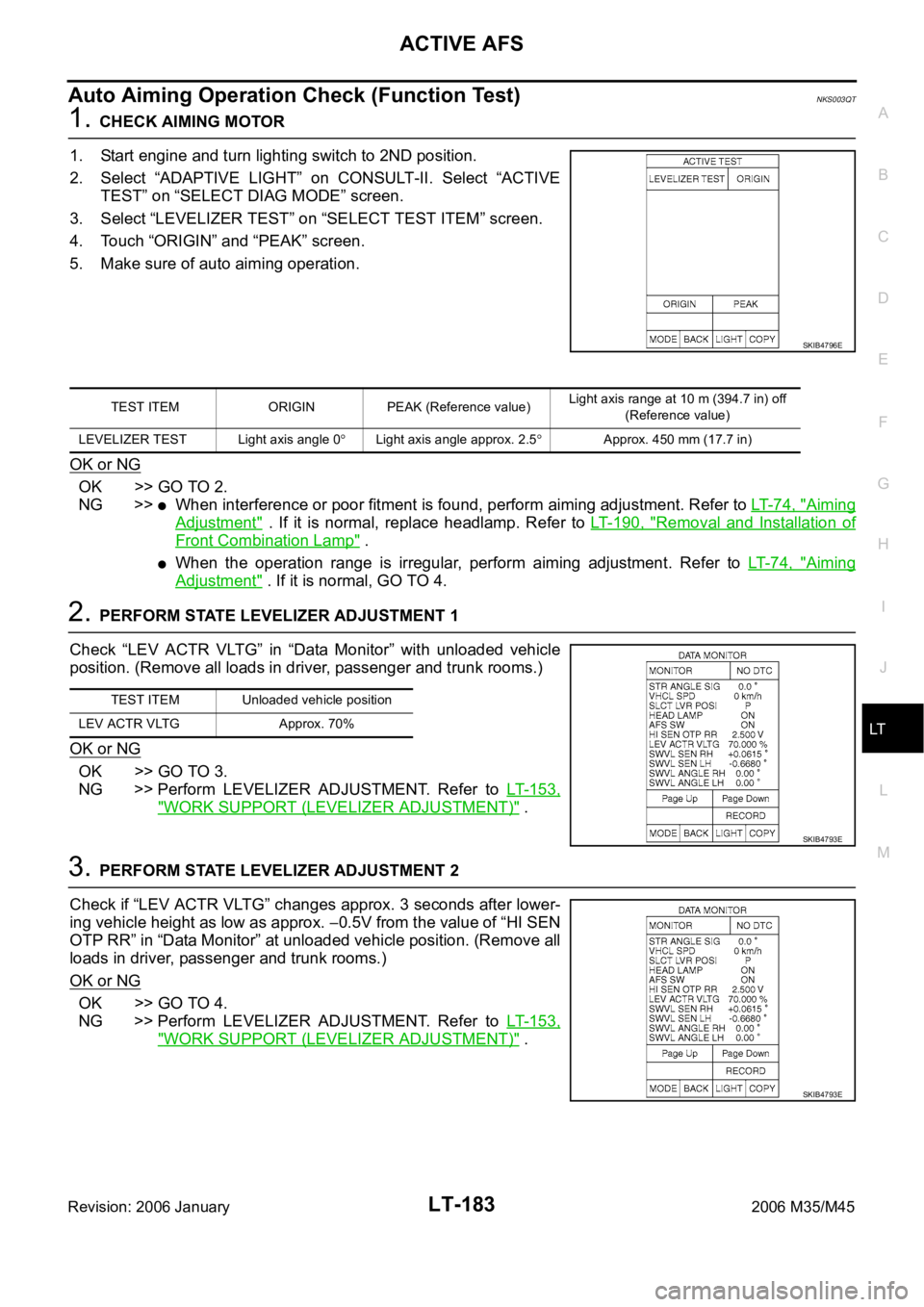
3. Select “LEVELIZER TEST” on “SELECT TEST ITEM” screen.
4. Touch “ORIGIN” and “PEAK” screen.
5. Make sure of auto aiming operation.
OK or NG
OK >> GO TO 2.
NG >>
When interference or poor fitment is found, perform aiming adjustment. Refer to LT- 7 4 , "Aiming
Adjustment" . If it is normal, replace headlamp. Refer to LT- 1 9 0 , "Removal and Installation of
Front Combination Lamp" .
When the operation range is irregular, perform aiming adjustment. Refer to LT- 7 4 , "Aiming
Adjustment" . If it is normal, GO TO 4.
2. PERFORM STATE LEVELIZER ADJUSTMENT 1
Check “LEV ACTR VLTG” in “Data Monitor” with unloaded vehicle
position. (Remove all loads in driver, passenger and trunk rooms.)
OK or NG
OK >> GO TO 3.
NG >> Perform LEVELIZER ADJUSTMENT. Refer to LT- 1 5 3 ,
"WORK SUPPORT (LEVELIZER ADJUSTMENT)" .
3. PERFORM STATE LEVELIZER ADJUSTMENT 2
Check if “LEV ACTR VLTG” changes approx. 3 seconds after lower-
ing vehicle height as low as approx.
0.5V from the value of “HI SEN
OTP RR” in “Data Monitor” at unloaded vehicle position. (Remove all
loads in driver, passenger and trunk rooms.)
OK or NG
OK >> GO TO 4.
NG >> Perform LEVELIZER ADJUSTMENT. Refer to LT- 1 5 3 ,
"WORK SUPPORT (LEVELIZER ADJUSTMENT)" .
SKIB4796E
TEST ITEM ORIGIN PEAK (Reference value)Light axis range at 10 m (394.7 in) off
(Reference value)
LEVELIZER TEST Light axis angle 0
Light axis angle approx. 2.5Approx. 450 mm (17.7 in)
TEST ITEM Unloaded vehicle position
LEV ACTR VLTG Approx. 70%
SKIB4793E
SKIB4793E
Page 4620 of 5621

FRONT FOG LAMP
LT-193
C
D
E
F
G
H
I
J
L
MA
B
LT
Revision: 2006 January2006 M35/M45
FRONT FOG LAMPPFP:26150
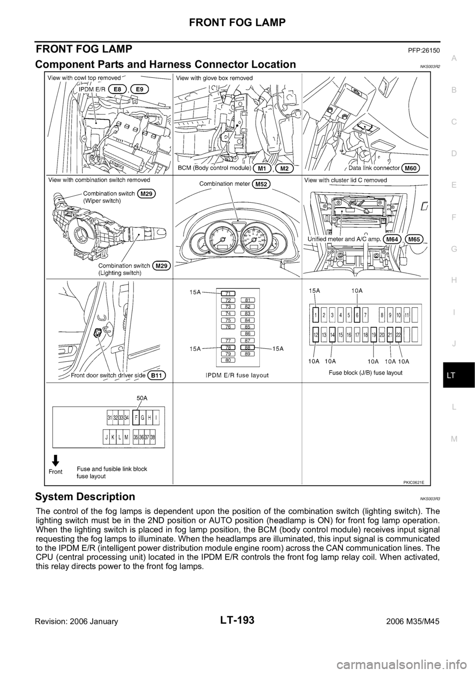
Component Parts and Harness Connector LocationNKS003R2
System DescriptionNKS003R3
The control of the fog lamps is dependent upon the position of the combination switch (lighting switch). The
lighting switch must be in the 2ND position or AUTO position (headlamp is ON) for front fog lamp operation.
When the lighting switch is placed in fog lamp position, the BCM (body control module) receives input signal
requesting the fog lamps to illuminate. When the headlamps are illuminated, this input signal is communicated
to the IPDM E/R (intelligent power distribution module engine room) across the CAN communication lines. The
CPU (central processing unit) located in the IPDM E/R controls the front fog lamp relay coil. When activated,
this relay directs power to the front fog lamps.
PKIC0621E
Page 4622 of 5621

FRONT FOG LAMP
LT-195
C
D
E
F
G
H
I
J
L
MA
B
LT
Revision: 2006 January2006 M35/M45
FOG LAMP OPERATION
The fog lamp switch is built in combination switch. The lighting switch must be in 2ND position or AUTO posi-
tion (headlamp is ON) and fog lamp switch must be ON for fog lamp operation.
With the fog lamp switch in the ON position, the CPU located in IPDM E/R grounds coil side of the fog lamp
relay. Fog lamp relay then directs power
through IPDM E/R terminal 37
to front fog lamp RH terminal 1,
through IPDM E/R terminal 36
to front fog lamp LH terminal 1.
Ground is supplied
to front fog lamp RH terminal 2
through grounds E22 and E43,
to front fog lamp LH terminal 2
through grounds E22 and E43.
With power and grounds supplied, the front fog lamps illuminate.
The unified meter and A/C amp. that received the front fog lamp request signal by BCM across the CAN com-
munication makes a front fog lamp indicator lamp turn on in combination meter.
COMBINATION SWITCH READING FUNCTION
Refer to BCS-3, "COMBINATION SWITCH READING FUNCTION" .
EXTERIOR LAMP BATTERY SAVER CONTROL
When the combination switch (lighting switch) is in the 2ND position (ON), and the ignition switch is turned
from ON or ACC to OFF, the battery saver control function is activated.
Under this condition, the headlamps remain illuminated for 5 minutes, then the headlamps are turned off.
Exterior lamp battery saver control mode can be changed by the function setting of CONSULT-II.
CAN Communication System DescriptionNKS003R4
CAN (Controller Area Network) is a serial communication line for real time application. It is an on-vehicle mul-
tiplex communication line with high data communication speed and excellent error detection ability. Many elec-
tronic control units are equipped onto a vehicle, and each control unit shares information and links with other
control units during operation (not independent). In CAN communication, control units are connected with 2
communication lines (CAN H line, CAN L line) allowing a high rate of information transmission with less wiring.
Each control unit transmits/receives data but selectively reads required data only.
CAN Communication UnitNKS003R5
Refer to LAN-34, "CAN Communication Unit" .
Page 4629 of 5621

LT-202
FRONT FOG LAMP
Revision: 2006 January2006 M35/M45
Terminals and Reference Values for IPDM E/RNKS003R9
How to Perform Trouble DiagnosesNKS003RA
1. Confirm the symptom or customer complaint.
2. Understand operation description and function description. Refer to LT- 1 9 3 , "
System Description" .
3. Perform the Preliminary Check. Refer to LT-202, "
Preliminary Check" .
4. Check symptom and repair or replace the cause of malfunction.
5. Does the front fog lamp operate normally? If YES, GO TO 6. If NO, GO TO 4.
6. INSPECTION END
Preliminary CheckNKS003RB
CHECK POWER SUPPLY AND GROUND CIRCUIT
1. CHECK FUSE
Check for blown fuses.
Refer to LT-197, "Wiring Diagram — F/FOG —" .
OK or NG
OK >> GO TO 2.
NG >> If fuse or fusible link is blown, be sure to eliminate cause of malfunction before installing new fuse
or fusible link. Refer to PG-3, "
POWER SUPPLY ROUTING CIRCUIT" .
Terminal
No.Wire
colorSignal nameMeasuring condition
Reference value
Ignition
switchOperation or condition
36 L/Y Front fog lamp (LH) ONLighting switch must be in
the 2ND position or AUTO
position (headlamp is ON)Front fog lamp switch: OFF Approx. 0V
Front fog lamp switch: ON Battery voltage
37 W/R Front fog lamp (RH) ONLighting switch must be in
the 2ND position or AUTO
position (headlamp is ON)Front fog lamp switch: OFF Approx. 0V
Front fog lamp switch: ON Battery voltage
38 B Ground ON — Approx. 0V
49 L CAN
H — — —
50 P CAN
L — — —
51 B Ground ON — Approx. 0V
Unit Power source Fuse and fusible link No.
BCMBatteryF
21
Ignition switch ON or START position 1
Ignition switch ACC or ON position 6
IPDM E/R Battery71
88
78
Page 4630 of 5621

FRONT FOG LAMP
LT-203
C
D
E
F
G
H
I
J
L
MA
B
LT
Revision: 2006 January2006 M35/M45
2. CHECK POWER SUPPLY CIRCUIT
1. Turn ignition switch OFF.
2. Disconnect BCM connector.
3. Check voltage between BCM harness connector and ground.
OK or NG
OK >> GO TO 3.
NG >> Check harness for open or short between BCM and
fuse.
3. CHECK GROUND CIRCUIT
Check continuity between BCM harness connector and ground.
OK or NG
OK >> INSPECTION END
NG >> Check harness ground circuit.
CONSULT-II Functions (BCM)NKS003RC
Refer to LT- 5 7 , "CONSULT-II Functions (BCM)" in HEADLAMP —XENON TYPE—.
Refer to LT- 2 2 , "
CONSULT-II Functions (BCM)" in HEADLAMP —CONVENTIONAL TYPE—.
CONSULT-II Functions (IPDM E/R)NKS003RD
Refer to LT- 6 0 , "CONSULT-II Functions (IPDM E/R)" in HEADLAMP —XENON TYPE—.
Refer to LT- 2 5 , "
CONSULT-II Functions (IPDM E/R)" in HEADLAMP —CONVENTIONAL TYPE—.
Terminal Ignition switch position
(+)
(-) OFF ACC ON
BCM
connectorTerminal
M111
GroundApprox. 0VBattery
voltageBattery
voltage
38 Approx. 0V Approx. 0VBattery
voltage
M242Battery
voltageBattery
voltageBattery
voltage
55Battery
voltageBattery
voltageBattery
voltage
PKIA5204E
BCM connector Terminal
GroundContinuity
M2 52 Yes
SKIB5125E
Page 4636 of 5621

FRONT FOG LAMP
LT-209
C
D
E
F
G
H
I
J
L
MA
B
LT
Revision: 2006 January2006 M35/M45
3. CHECK CAN COMMUNICATIONS BETWEEN BCM AND IPDM E/R
Select “BCM” on CONSULT-II, and perform self-diagnosis for “BCM”.
Display of self-diagnosis results
NO DTC>> Replace IPDM E/R. Refer to PG-31, "Removal and
Installation of IPDM E/R" .
CAN COMM CIRCUIT>> Refer to BCS-15, "
CAN Communication
Inspection Using CONSULT-II (Self-Diagnosis)" .
Aiming AdjustmentNKS003RH
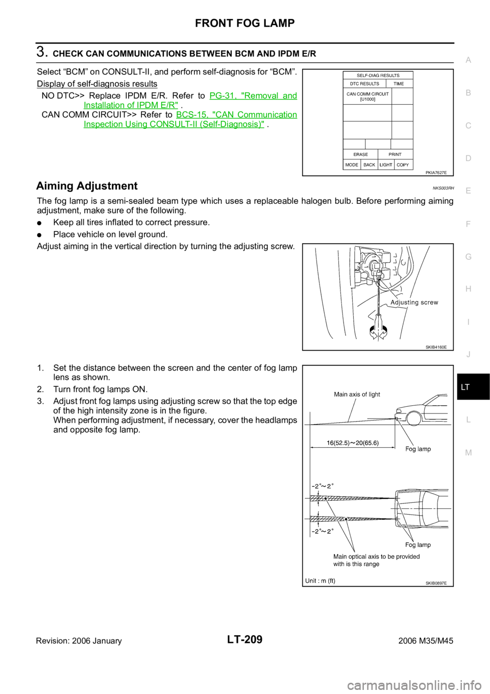
The fog lamp is a semi-sealed beam type which uses a replaceable halogen bulb. Before performing aiming
adjustment, make sure of the following.
Keep all tires inflated to correct pressure.
Place vehicle on level ground.
Adjust aiming in the vertical direction by turning the adjusting screw.
1. Set the distance between the screen and the center of fog lamp
lens as shown.
2. Turn front fog lamps ON.
3. Adjust front fog lamps using adjusting screw so that the top edge
of the high intensity zone is in the figure.
When performing adjustment, if necessary, cover the headlamps
and opposite fog lamp.
PKIA7627E
SKIB4160E
SKIB0897E
Page 4656 of 5621

TURN SIGNAL AND HAZARD WARNING LAMPS
LT-229
C
D
E
F
G
H
I
J
L
MA
B
LT
Revision: 2006 January2006 M35/M45
Bulb Replacement/Removal and Installation of Side Turn Signal LampNKS003RX
: Vehicle front
REMOVAL
1. While pressing the side turn signal lamp (1) to direction A (Ve h i -
cle front), pull direction B of it and remove.
2. Disconnect side turn signal lamp connector.
CAUTION:
Support side turn signal lamp harness with tape so that it
won't fall into the front fender.
Fix the pawl side of side turn signal lamp housing back at
first. Then install side turn signal lamp while pushing
resin clip side.
3. Turn bulb socket (1) counterclockwise and unlock it.
4. Remove bulb (2).
INSTALLATION
Installation is the reverse order of removal.
Bulb Replacement (Front Turn Signal Lamp)NKS003RY
Refer to LT- 3 9 , "Bulb Replacement" in “HEADLAMP -CONVENTIONAL TYPE-”.
Refer to LT- 7 5 , "
Bulb Replacement" in “HEADLAMP -XENON TYPE-”.
Bulb Replacement (Rear Turn Signal Lamp)NKS003RZ
Refer to LT-266, "Bulb Replacement" .
Removal and Installation of Front Turn Signal LampNKS003S0
Refer to LT- 4 1 , "Removal and Installation" .
Removal and Installation of Rear Turn Signal Lamp NKS003S1
Refer to LT-266, "Removal and Installation" .
SKIB4184E
Side turn signal lamp : 12V - 5W
SKIB4185E