stall INFINITI M35 2006 Factory Service Manual
[x] Cancel search | Manufacturer: INFINITI, Model Year: 2006, Model line: M35, Model: INFINITI M35 2006Pages: 5621, PDF Size: 65.56 MB
Page 608 of 5621
REFRIGERANT LINES
ATC-161
C
D
E
F
G
H
I
K
L
MA
B
AT C
Revision: 2006 January2006 M35/M45
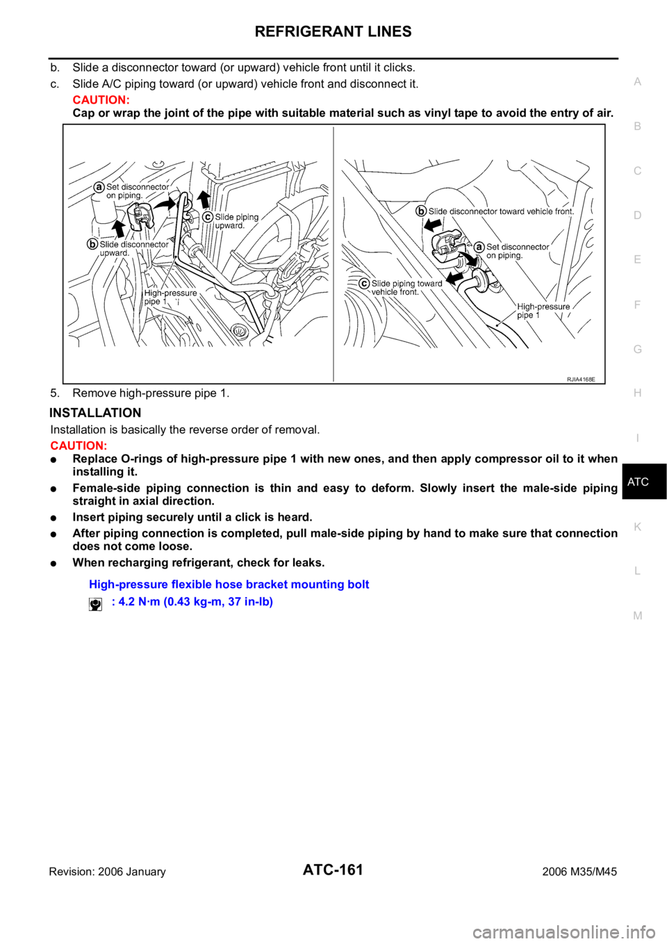
b. Slide a disconnector toward (or upward) vehicle front until it clicks.
c. Slide A/C piping toward (or upward) vehicle front and disconnect it.
CAUTION:
Cap or wrap the joint of the pipe with suitable material such as vinyl tape to avoid the entry of air.
5. Remove high-pressure pipe 1.
INSTALLATION
Installation is basically the reverse order of removal.
CAUTION:
Replace O-rings of high-pressure pipe 1 with new ones, and then apply compressor oil to it when
installing it.
Female-side piping connection is thin and easy to deform. Slowly insert the male-side piping
straight in axial direction.
Insert piping securely until a click is heard.
After piping connection is completed, pull male-side piping by hand to make sure that connection
does not come loose.
When recharging refrigerant, check for leaks.
RJIA4168E
High-pressure flexible hose bracket mounting bolt
: 4.2 Nꞏm (0.43 kg-m, 37 in-lb)
Page 609 of 5621

ATC-162
REFRIGERANT LINES
Revision: 2006 January2006 M35/M45
Removal and Installation of Low-Pressure Pipe 1 and High-Pressure Pipe 2NJS000HS
REMOVAL
1. Use a refrigerant collecting equipment (for HFC-134a) to discharge the refrigerant.
2. Set the temperature control switch (passenger side) at 18
C (60F), and then disconnect the battery cable
from the negative terminal.
3. Remove cowl top cover. Refer to EI-18, "
COWL TOP" .
4. Remove mounting bolt from low-pressure flexible hose bracket.
5. Remove high-pressure pipe 1 from vehicle clip.
6. Disconnect one-touch joints.
a. Set a disconnector [high-pressure side (SST: 9253089908), low-
pressure side (SST: 9253089916)] on A/C piping.
b. Slide a disconnector toward vehicle front until it clicks.
c. Slide A/C piping toward vehicle front and disconnect it.
CAUTION:
Cap or wrap the joint of the pipe with suitable material such
as vinyl tape to avoid the entry of air.
7. Remove instrument passenger lower panel and glove box. Refer
to IP-10, "
INSTRUMENT PANEL ASSEMBLY" .
8. Remove foot grille (right). Refer to ATC-149, "
Removal of Foot
Grilles" .
9. Remove air mix door motor (passenger side). Refer to ATC-141, "
AIR MIX DOOR MOTOR" .
10. Remove mode door motor (passenger side). Refer to ATC-140, "
MODE DOOR MOTOR" .
11. Remove main link (right) and max. cool door link (right). Refer to ATC-135, "
HEATER & COOLING UNIT
ASSEMBLY" .
12. Remove mounting screws, and then remove evaporator cover.
RJIA4169E
RJIA4117E
RJIA4170E
Page 610 of 5621
REFRIGERANT LINES
ATC-163
C
D
E
F
G
H
I
K
L
MA
B
AT C
Revision: 2006 January2006 M35/M45
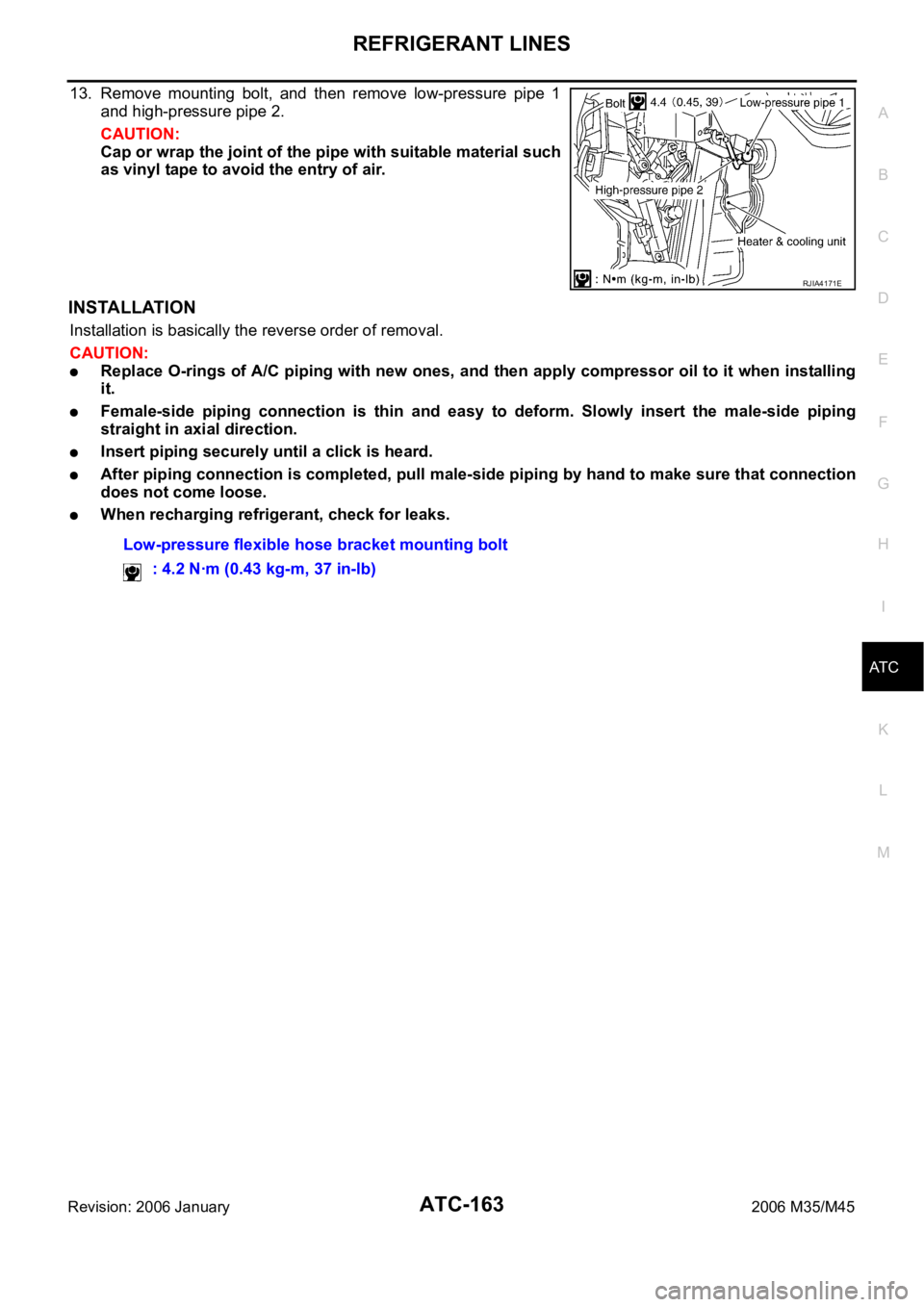
13. Remove mounting bolt, and then remove low-pressure pipe 1
and high-pressure pipe 2.
CAUTION:
Cap or wrap the joint of the pipe with suitable material such
as vinyl tape to avoid the entry of air.
INSTALLATION
Installation is basically the reverse order of removal.
CAUTION:
Replace O-rings of A/C piping with new ones, and then apply compressor oil to it when installing
it.
Female-side piping connection is thin and easy to deform. Slowly insert the male-side piping
straight in axial direction.
Insert piping securely until a click is heard.
After piping connection is completed, pull male-side piping by hand to make sure that connection
does not come loose.
When recharging refrigerant, check for leaks.
RJIA4171E
Low-pressure flexible hose bracket mounting bolt
: 4.2 Nꞏm (0.43 kg-m, 37 in-lb)
Page 611 of 5621
ATC-164
REFRIGERANT LINES
Revision: 2006 January2006 M35/M45
Removal and Installation of Liquid TankNJS000HT
DISASSEMBLY AND ASSEMBLY
REMOVAL
1. Remove condenser. Refer to ATC-165, "Removal and Installation of Condenser" .
2. Clean liquid tank and its surrounding area, and remove dirt and rust from liquid tank.
CAUTION:
Be sure to clean carefully.
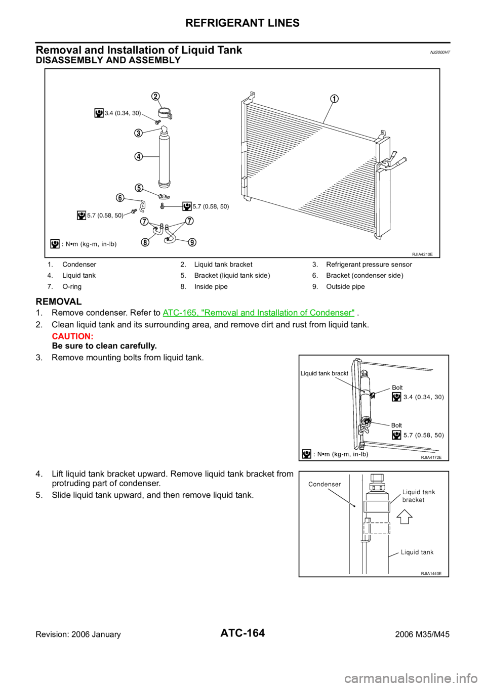
3. Remove mounting bolts from liquid tank.
4. Lift liquid tank bracket upward. Remove liquid tank bracket from
protruding part of condenser.
5. Slide liquid tank upward, and then remove liquid tank.
1. Condenser 2. Liquid tank bracket 3. Refrigerant pressure sensor
4. Liquid tank 5. Bracket (liquid tank side) 6. Bracket (condenser side)
7. O-ring 8. Inside pipe 9. Outside pipe
RJIA4210E
RJIA4172E
RJIA1440E
Page 612 of 5621
REFRIGERANT LINES
ATC-165
C
D
E
F
G
H
I
K
L
MA
B
AT C
Revision: 2006 January2006 M35/M45
INSTALLATION
Install liquid tank, and then install liquid tank bracket on condenser.
CAUTION:
Make sure liquid tank bracket is securely installed at protru-
sion of condenser. (Make sure liquid tank bracket does not
move to a position below center of liquid tank.)
Replace O-rings of A/C piping with new ones, and then
apply compressor oil to it when installing it.
When recharging refrigerant, check for leaks.
Removal and Installation of CondenserNJS000HU
REMOVAL
1. Use a refrigerant collecting equipment (for HFC-134a) to discharge the refrigerant.
2. Remove engine cover. Refer to EM-14, "
ENGINE ROOM COVER" (VQ35DE) or EM-173, "ENGINE
ROOM COVER" (VK45DE).
3. Remove air cleaner case, air hose and air duct. Refer to EM-17, "
AIR CLEANER AND AIR DUCT"
(VQ35DE) or EM-177, "AIR CLEANER AND AIR DUCT" (VK45DE).
4. Remove engine under cover, using power tools.
5. Drain engine coolant. Refer to CO-11, "
Changing Engine Coolant" (VQ35DE) or CO-40, "Changing
Engine Coolant" (VK45DE).
6. Remove radiator fan shroud with cooling fan after (VK45DE). Refer to CO-51, "
COOLING FAN" .
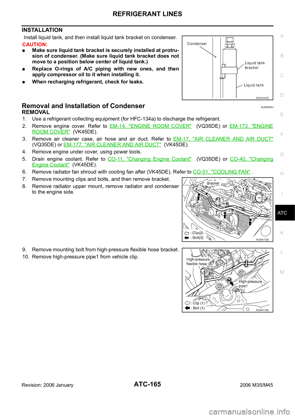
7. Remove mounting clips and bolts, and then remove bracket.
8. Remove radiator upper mount, remove radiator and condenser
to the engine side.
9. Remove mounting bolt from high-pressure flexible hose bracket.
10. Remove high-pressure pipe1 from vehicle clip.
RJIA1441E
RJIA4173E
RJIA4174E
Page 614 of 5621
REFRIGERANT LINES
ATC-167
C
D
E
F
G
H
I
K
L
MA
B
AT C
Revision: 2006 January2006 M35/M45
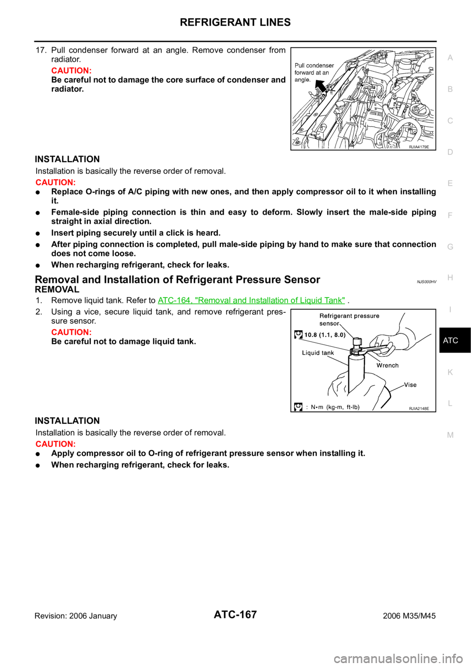
17. Pull condenser forward at an angle. Remove condenser from
radiator.
CAUTION:
Be careful not to damage the core surface of condenser and
radiator.
INSTALLATION
Installation is basically the reverse order of removal.
CAUTION:
Replace O-rings of A/C piping with new ones, and then apply compressor oil to it when installing
it.
Female-side piping connection is thin and easy to deform. Slowly insert the male-side piping
straight in axial direction.
Insert piping securely until a click is heard.
After piping connection is completed, pull male-side piping by hand to make sure that connection
does not come loose.
When recharging refrigerant, check for leaks.
Removal and Installation of Refrigerant Pressure SensorNJS000HV
REMOVAL
1. Remove liquid tank. Refer to ATC-164, "Removal and Installation of Liquid Tank" .
2. Using a vice, secure liquid tank, and remove refrigerant pres-
sure sensor.
CAUTION:
Be careful not to damage liquid tank.
INSTALLATION
Installation is basically the reverse order of removal.
CAUTION:
Apply compressor oil to O-ring of refrigerant pressure sensor when installing it.
When recharging refrigerant, check for leaks.
RJIA4179E
RJIA2148E
Page 615 of 5621
ATC-168
REFRIGERANT LINES
Revision: 2006 January2006 M35/M45
Removal and Installation of EvaporatorNJS000HW
REMOVAL
1. Remove low-pressure pipe 1 and high-pressure pipe 2. Refer to ATC-162, "Removal and Installation of
Low-Pressure Pipe 1 and High-Pressure Pipe 2" .
CAUTION:
Cap or wrap the joint of the pipe with suitable material such as vinyl tape to avoid the entry of air.
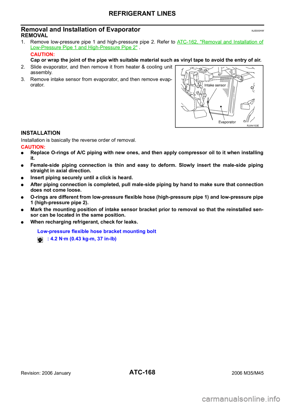
2. Slide evaporator, and then remove it from heater & cooling unit
assembly.
3. Remove intake sensor from evaporator, and then remove evap-
orator.
INSTALLATION
Installation is basically the reverse order of removal.
CAUTION:
Replace O-rings of A/C piping with new ones, and then apply compressor oil to it when installing
it.
Female-side piping connection is thin and easy to deform. Slowly insert the male-side piping
straight in axial direction.
Insert piping securely until a click is heard.
After piping connection is completed, pull male-side piping by hand to make sure that connection
does not come loose.
O-rings are different from low-pressure flexible hose (high-pressure pipe 1) and low-pressure pipe
1 (high-pressure pipe 2).
Mark the mounting position of intake sensor bracket prior to removal so that the reinstalled sen-
sor can be located in the same position.
When recharging refrigerant, check for leaks.
RJIA4103E
Low-pressure flexible hose bracket mounting bolt
: 4.2 Nꞏm (0.43 kg-m, 37 in-lb)
Page 616 of 5621
REFRIGERANT LINES
ATC-169
C
D
E
F
G
H
I
K
L
MA
B
AT C
Revision: 2006 January2006 M35/M45
Removal and Installation of Expansion ValveNJS000HX
REMOVAL
1. Remove evaporator. Refer to ATC-168, "Removal and Installation of Evaporator" .
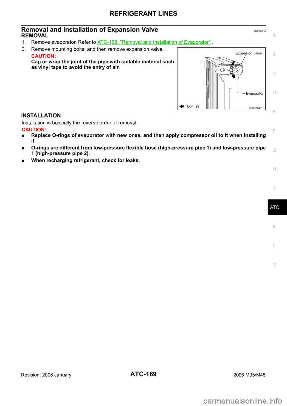
2. Remove mounting bolts, and then remove expansion valve.
CAUTION:
Cap or wrap the joint of the pipe with suitable material such
as vinyl tape to avoid the entry of air.
INSTALLATION
Installation is basically the reverse order of removal.
CAUTION:
Replace O-rings of evaporator with new ones, and then apply compressor oil to it when installing
it.
O-rings are different from low-pressure flexible hose (high-pressure pipe 1) and low-pressure pipe
1 (high-pressure pipe 2).
When recharging refrigerant, check for leaks.
RJIA1864E
Page 623 of 5621

AV-2Revision: 2006 January2006 M35/M45 Rear View Monitor Guiding Line Adjustment ........101
CONSULT-II Functions (Multi AV) .........................102
OPERATION PROCEDURE ..............................102
SELF-DIAG RESULTS ......................................103
DATA MONITOR ................................................105
AV COMM MONITOR ........................................106
ECU PART NUMBER ........................................107
TROUBLE DIAGNOSIS ..........................................108
Multifunction Switch Cannot Be Operated ............108
RGB Image Is Not Displayed ................................108
RGB Screen Is Rolling ..........................................109
Rear View Monitor Image Is Not Displayed ..........109
DVD IMAGE IS DISPLAYED .............................109
DVD IMAGE IS NOT DISPLAYED .....................112
IT CANNOT BE SWITCHED TO REAR VIEW
MONITOR IMAGE .............................................112
DVD Image Is Not Displayed ................................113
Warning Message of Whether Rear View Image Is
Rolling or Not Displayed .......................................115
DVD Operation Screen Is Not Displayed ..............115
It Cannot Be Switched to DVD Mode ...................115
Sound Is Not Output (Voice Guidance and TEL
Voice Are Normal) ................................................116
DVD AND AUDIO SOUND ARE NOT OUTPUT .116
DVD SOUND IS NOT OUTPUT ........................116
Voice Activated Control System Is Not Activated . 116
THE SCREEN IS SWITCHED BY PRESSING
THE STEERING SWITCH .................................116
THE SCREEN IS NOT SWITCHED BY PRESS-
ING THE STEERING SWITCH .........................117
Steering Switch Cannot Be Operated ...................118
NONE OF THE OPERATIONS WORK. .............118
“ENTER”, “MENU UP-DOWN”, AND “SOURCE”
SWITCHES ARE NOT OPERATED ..................118
“PTT/TEL”, “BACK”, AND “VOLUME CONTROL”
SWITCHES ARE NOT OPERATED ..................119
The Hands-Free Phone Cannot Be Used .............119
THE VOICE CANNOT BE HEARD ....................119
THE VOICE CANNOT BE TRANSMITTED .......120
Voice Guidance Is Not Heard (Base System) .......120
Voice Guidance Is Not Heard (BOSE System) .....121
Example of Symptoms Judged Not Malfunction ...122
BASIC OPERATION ..........................................122
VEHICLE ICON .................................................122
MAP DVD-ROM .................................................123
ROUTE CALCULATION AND VISUAL GUID-
ANCE .................................................................123
VOICE GUIDANCE ...........................................124
VOICE RECOGNITION .....................................124
REAR VIEW MONITOR ....................................124
EXAMPLES OF VEHICLE MARK DISPLACE-
MENT ................................................................125
VEHICLE MARK SHOWS A POSITION WHICH
IS COMPLETELY WRONG ...............................128
VEHICLE MARK JUMPS ...................................128
VEHICLE MARK IS IN A RIVER OR SEA .........129
VEHICLE MARK AUTOMATICALLY ROTATES .129
WHEN DRIVING ON SAME ROAD, SOME-
TIMES VEHICLE MARK IS IN RIGHT PLACE AND SOMETIMES IT IS WRONG PLACE ........129
LOCATION CORRECTION BY MAP-MATCH-
ING IS SLOW ....................................................
.129
ALTHOUGH GPS RECEIVING DISPLAY IS
GREEN, VEHICLE MARK DOES NOT RETURN
TO CORRECT LOCATION ................................129
NAME OF CURRENT PLACE IS NOT DIS-
PLAYED .............................................................129
CONTENTS OF DISPLAY DIFFER FOR BIRD-
VIEW® AND THE (FLAT) MAP SCREEN ..........129
REMOVAL AND INSTALLATION ............................130
Removal and Installation/Precautions for Replace-
ment ......................................................................130
REMOVAL OF BATTERY ..................................130
Audio Unit .............................................................130
REMOVAL ..........................................................130
INSTALLATION ..................................................130
Front Door Speaker ............................................. .130
REMOVAL ..........................................................130
INSTALLATION ..................................................130
Rear Door Speaker ...............................................131
REMOVAL ..........................................................131
INSTALLATION ..................................................131
Tweeter .................................................................131
REMOVAL ..........................................................131
INSTALLATION ..................................................131
Center Speaker .....................................................131
REMOVAL ..........................................................131
INSTALLATION ..................................................131
Seat Speaker ........................................................132
REMOVAL ..........................................................132
INSTALLATION ..................................................132
Rear Surround Speaker ........................................132
REMOVAL ..........................................................132
INSTALLATION ..................................................132
Woofer ..................................................................132
REMOVAL ..........................................................132
INSTALLATION ..................................................133
BOSE Amp ............................................................133
REMOVAL ..........................................................133
INSTALLATION ..................................................133
AudioPilot® Microphone .......................................133
REMOVAL ..........................................................133
INSTALLATION ..................................................133
Satellite Radio Tuner .........................................
....133
REMOVAL ..........................................................133
INSTALLATION ..................................................134
Antenna Amp ........................................................134
REMOVAL ..........................................................134
INSTALLATION ..................................................134
Satellite Radio Antenna ........................................134
REMOVAL ..........................................................134
INSTALLATION ..................................................135
Splitter ...................................................................135
REMOVAL ..........................................................135
INSTALLATION ..................................................135
AV (NAVI) Control Unit ......................................... .135
REMOVAL ..........................................................135
INSTALLATION ..................................................136
Page 624 of 5621
AV-3
C
D
E
F
G
H
I
J
L
MA
B
AV
Revision: 2006 January2006 M35/M45 Front Display Unit (Base System) ........................136
REMOVAL ........................................................
.136
INSTALLATION .................................................136
Front Display Unit (BOSE System) ......................137
REMOVAL ........................................................
.137
INSTALLATION .................................................137
Multifunction Switch .............................................137
REMOVAL ........................................................
.137
INSTALLATION .................................................137
Preset Switch .......................................................137
REMOVAL ........................................................
.137
INSTALLATION .................................................138
Steering Switch ....................................................138
REMOVAL ........................................................
.138
INSTALLATION .................................................138
DVD Player ..........................................................138
REMOVAL ........................................................
.138
INSTALLATION .................................................139
Auxiliary Input Jacks ............................................140
REMOVAL ........................................................
.140
INSTALLATION .................................................140
Microphone ..........................................................140
REMOVAL ........................................................
.140
INSTALLATION .................................................140
GPS Antenna .......................................................140
REMOVAL ........................................................
.140
INSTALLATION .................................................141
Camera Control Unit ............................................142
REMOVAL ........................................................
.142
INSTALLATION .................................................142
Rear View Camera ...............................................142
REMOVAL ........................................................
.142
INSTALLATION .................................................142
Steering Angle Sensor .........................................142
REMOVAL ........................................................
.142
INSTALLATION .................................................143
WITH MOBILE ENTERTAINMENT SYSTEM
PRECAUTION ........................................................144
Precautions for Supplemental Restraint System
(SRS) “AIR BAG” and “SEAT BELT PRE-TEN-
SIONER” ..............................................................144
Precautions for Trouble Diagnosis .......................144
AV COMMUNICATION SYSTEM ......................144
Precautions for Harness Repair ...........................144
AV COMMUNICATION SYSTEM ......................144
PREPARATION .......................................................145
Commercial Service Tools ....................................145
SYSTEM DESCRIPTION ........................................146
System Functions .................................................146
AUDIO ...............................................................146
VEHICLE INFORMATION SYSTEM .................146
NAVIGATION SYSTEM .....................................146
MOBILE ENTERTAINMENT SYSTEM ..............148
HANDS-FREE PHONE .....................................148
REAR VIEW MONITOR ....................................148Component Description ........................................149
AUDIO UNIT ..................................................... .149
BOSE AMP ........................................................149
SATELLITE TUNER ..........................................150
AV CONTROL UNIT (WITHOUT NAVI) .............150
NAVI CONTROL UNIT (WITH NAVI) .................150
FRONT DISPLAY UNIT .....................................150
REAR DISPLAY UNIT .......................................151
VIDEO DISTRIBUTOR ......................................151
DVD PLAYER ....................................................151
CAMERA CONTROL UNIT ...............................151
CAN Communication System Description ............152
CAN Communication Unit .....................................152
Schematic — BOSE Audio 2ch System — ...........153
W i r i n g D i a g r a m — A V — / B O S E A u d i o 2 c h S y s t e m .156
Schematic — BOSE Surround Audio 5.1ch System
— ..........................................................................175
Wiring Diagram — AV — / BOSE Surround Audio
5.1ch System ........................................................178
Component Parts Location ...................................202
Location of Antenna ..............................................203
TERMINALS AND REFERENCE VALUE FOR CON-
TROL UNIT .............................................................204
Audio Unit .............................................................204
BOSE Amp ...........................................................206
Satellite Radio Tuner ............................................210
AV (NAVI) Control Unit .........................................211
Video Distributor ...................................................214
Front Display Unit ................................................
.219
Rear Display Unit ..................................................221
DVD Player ...........................................................223
Headphone Amp ...................................................226
Camera Control Unit ............................................ .227
DIAGNOSIS SYSTEM .............................................230
Multifunction Switch Self-Diagnosis Function .......230
SELF-DIAGNOSIS MODE ................................230
FINISHING SELF-DIAGNOSIS MODE .............230
Multi AV System Diagnosis Functions ..................230
On Board Diagnosis .............................................230
DESCRIPTION ..................................................230
STARTING PROCEDURE .................................231
Self Diagnosis .......................................................232
DIAGNOSIS RESULTS .....................................233
Confirmation/Adjustment Mode ............................235
DISPLAY DIAGNOSIS .......................................235
VEHICLE SIGNALS ..........................................236
SPEAKER TEST ...............................................236
CLIMATE CONTROL .........................................236
NAVIGATION .....................................................237
ERROR HISTORY .............................................237
VEHICLE CAN DIAGNOSIS .............................241
AV COMM DIAGNOSIS .....................................241
HANDSFREE PHONE ......................................242
REAR DISPLAY .................................................242
CAMERA CONT. ...............................................243
BLUETOOTH .....................................................244
DELETE UNIT CONNECTION LOG .................244