engine INFINITI M35 2006 Factory Service Manual
[x] Cancel search | Manufacturer: INFINITI, Model Year: 2006, Model line: M35, Model: INFINITI M35 2006Pages: 5621, PDF Size: 65.56 MB
Page 351 of 5621

from the A/")
AT-272
TRANSMISSION ASSEMBLY
Revision: 2006 January2006 M35/M45
VK45DE models
REMOVAL
CAUTION:
When removing the A/T assembly from engine, first remove the crankshaft position sensor (POS)
from the A/T assembly.
Be careful not to damage sensor edge.
1. Disconnect the battery cable from the negative terminal.
2. Remove engine under cover with power tool.
3. Remove A/T fluid level gauge.
4. Remove exhaust front tube and center muffler with power tool. Refer to EX-5, "
Removal and Installation"
(for VQ35DE engine), EX-7, "Removal and installation" (for VK45DE engine).
5. Remove heat insulator.
6. Remove rear propeller shaft. Refer to PR-8, "
Removal and Installation" .
7. Remove rack stay. Refer to FSU-9, "
Removal and Installation" .
8. Remove exhaust mounting bracket. Refer to EX-5, "
Removal and Installation" (for VQ35DE engine), EX-
7, "Removal and installation" (for VK45DE engine).
9. Remove control rod. Refer to AT-226, "
Control Rod Removal and Installation" .
SCIA7320E
1. A/T assembly 2. A/T fluid level gauge 3. A/T fluid charging pipe
4. O-ring 5. Copper washer 6. Fluid cooler tube
7. Bracket 8. Rear engine mounting member 9. Engine mounting insulator (rear)
Refer to GI section to make sure icons (symbol marks) in the figure. Refer to GI-11, "
Components" .
However, refer to following symbols for others.
:For tightening torque, refer to AT-274, "
INSTALLATION" .
Page 352 of 5621
 (1) from A/T assem-
bly.
CAUTION:
Do not subject it to impact b")
TRANSMISSION ASSEMBLY
AT-273
D
E
F
G
H
I
J
K
L
MA
B
AT
Revision: 2006 January2006 M35/M45
10. Remove crankshaft position sensor (POS) (1) from A/T assem-
bly.
CAUTION:
Do not subject it to impact by dropping or hitting it.
Do not disassemble.
Do not allow metal filings, etc., to get on the sensor's
front edge magnetic area.
Do not place in an area affected by magnetism.
11. Remove starter motor. Refer to SC-17, "
VQ35DE ENGINE
MODELS (2WD)" , SC-19, "VK45DE ENGINE MODELS" .
12. Remove rear cover plate. Refer to EM-29, "
Removal and Instal-
lation (2WD Models)" (for VQ35DE engine).
13. Remove rear plate cover. Refer to EM-29, "
Removal and Installation (2WD Models)" (for VQ35DE
engine), EM-187, "
Removal and Installation" (for VK45DE engine).
14. Turn crankshaft, and remove the four tightening bolts for drive
plate and torque converter.
CAUTION:
When turning the crankshaft, turn it clockwise as viewed
from the front of the engine.
15. Support A/T assembly with a transmission jack.
CAUTION:
When setting the transmission jack, be careful not to allow
it to collide against the drain plug.
16. Remove rear engine mounting member with power tool.
17. Remove engine mounting insulator (rear).
18. Disconnect A/T assembly harness connector.
19. Remove air breather hose. Refer to AT-269, "
Removal and Installation" .
20. Remove A/T fluid charging pipe from A/T assembly.
21. Remove O-ring from A/T fluid charging pipe.
22. Disconnect fluid cooler tube from A/T assembly.
23. Plug up openings such as the A/T fluid charging pipe hole, etc.
24. Remove bolts fixing A/T assembly to engine assembly with power tool.
25. Remove A/T assembly from vehicle.
CAUTION:
Secure torque converter to prevent it from dropping.
Secure A/T assembly to a transmission jack.
SCIA6506J
LCIA0335E
SCIA0499E
Page 353 of 5621

AT-274
TRANSMISSION ASSEMBLY
Revision: 2006 January2006 M35/M45
INSPECTION
Installation and Inspection of Torque Converter
After inserting a torque converter to a A/T, be sure to check dis-
tance “A” to ensure it is within the reference value limit.
INSTALLATION
Install the removed parts in the reverse order of the removal, while paying attention to the following work.
When installing A/T assembly to the engine assembly, attach the fixing bolts in accordance with the follow-
ing standard.
VQ35DE models
VK45DE models
*: No.2 bolt also secures A/T fluid charging pipe.
Align the positions of tightening bolts for drive plate with those of
the torque converter, and temporarily tighten the bolts. Then,
tighten the bolts with the specified torque. Refer to AT- 2 7 1 ,
"COMPONENTS" .
CAUTION:
When turning crankshaft, turn it clockwise as viewed from
the front of the engine.
When tightening the tightening bolts for the torque con-
verter after fixing the crankshaft pulley bolts, be sure to
confirm the tightening torque of the crankshaft pulley
mounting bolts. Refer to EM-72, "
INSTALLATION" (for
VQ35DE engine), EM-208, "
INSTALLATION" (for VK45DE
engine).
After converter is installed to drive plate, rotate crankshaft several turns and check to be sure that
A/T rotates freely without binding.Distance “A”
VQ35DE models: 25.0 mm (0.98 in) or more
VK45DE models: 22.0 mm (0.87 in) or more
SCIA5694E
Bolt No. 1234
Number of bolts 1 5 2 2
Bolt length
“ ”mm (in)55 (2.17) 65 (2.56) 65 (2.56) 35 (1.38)
Tightening torque
Nꞏm (kg-m, ft-lb)75
(7.7, 55)55
(5.6, 41)47
(4.8, 35)
SCIA3949E
Bolt No. 1 2* 3
Number of bolts 5 1 4
Bolt length
“ ”mm (in)70 (2.76) 70 (2.76) 65 (2.56)
Tightening torque
Nꞏm (kg-m, ft-lb)11 3
(12, 83)74
(7.5, 55)
SCIA7068E
SCIA2288E
Page 354 of 5621
TRANSMISSION ASSEMBLY
AT-275
D
E
F
G
H
I
J
K
L
MA
B
AT
Revision: 2006 January2006 M35/M45
Install crankshaft position sensor (POS). Refer to EM-29, "Removal and Installation (2WD Models)" (for
VQ35DE engine), EM-187, "
Removal and Installation" (for VK45DE engine).
After completing installation, check A/T fluid leakage, A/T fluid level and A/T position. Refer to AT- 1 3 ,
"Checking A/T Fluid" , AT-228, "Checking of A/T Position" .
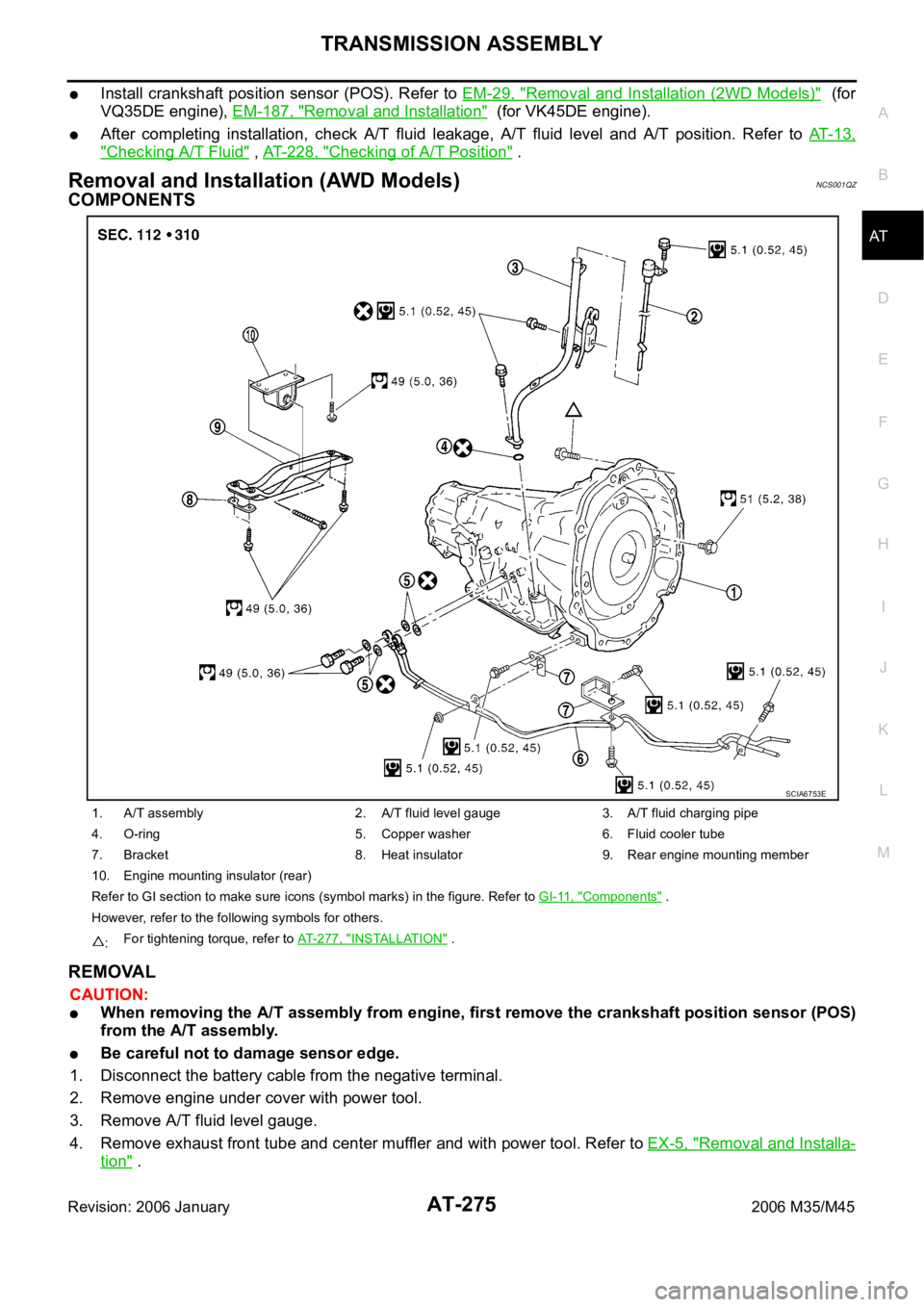
Removal and Installation (AWD Models) NCS001QZ
COMPONENTS
REMOVAL
CAUTION:
When removing the A/T assembly from engine, first remove the crankshaft position sensor (POS)
from the A/T assembly.
Be careful not to damage sensor edge.
1. Disconnect the battery cable from the negative terminal.
2. Remove engine under cover with power tool.
3. Remove A/T fluid level gauge.
4. Remove exhaust front tube and center muffler and with power tool. Refer to EX-5, "
Removal and Installa-
tion" .
1. A/T assembly 2. A/T fluid level gauge 3. A/T fluid charging pipe
4. O-ring 5. Copper washer 6. Fluid cooler tube
7. Bracket 8. Heat insulator 9. Rear engine mounting member
10. Engine mounting insulator (rear)
Refer to GI section to make sure icons (symbol marks) in the figure. Refer to GI-11, "
Components" .
However, refer to the following symbols for others.
:For tightening torque, refer to AT-277, "
INSTALLATION" .
SCIA6753E
Page 355 of 5621

AT-276
TRANSMISSION ASSEMBLY
Revision: 2006 January2006 M35/M45
5. Remove heat insulator.
6. Remove rear propeller shaft. Refer to PR-8, "
Removal and Installation" .
7. Remove front cross bar with power tool. Refer to FSU-26, "
Removal and Installation" .
8. Remove exhaust mounting bracket. Refer to EX-5, "
Removal and Installation" .
9. Remove three way catalyst. Refer to EX-5, "
Removal and Installation" .
10. Remove front propeller shaft. Refer to PR-5, "
Removal and Installation" .
11. Remove control rod. Refer to AT-226, "
Control Rod Removal and Installation" .
12. Remove crankshaft position sensor (POS) (1) from A/T assem-
bly.
CAUTION:
Do not subject it to impact by dropping or hitting it.
Do not disassemble.
Do not allow metal filings, etc., to get on the sensor's
front edge magnetic area.
Do not place in an area affected by magnetism.
13. Remove starter motor. Refer to SC-18, "
VQ35DE ENGINE
MODELS (AWD)" .
14. Remove rear plate cover. Refer to EM-36, "
Removal and Instal-
lation (AWD Models)" .
15. Turn crankshaft, and remove the four tightening bolts for drive
plate and torque converter.
CAUTION:
When turning the crankshaft, turn it clockwise as viewed
from the front of the engine.
16. Support A/T assembly with a transmission jack.
CAUTION:
When setting the transmission jack, be careful not to allow
it to collide against the drain plug.
17. Remove rear engine mounting member with power tool.
18. Remove engine mounting insulator (rear).
19. Disconnect A/T assembly harness connector.
20. Remove air breather hose. Refer to AT- 2 6 9 , "
Removal and Installation" .
21. Remove A/T fluid charging pipe from A/T assembly.
22. Remove O-ring from A/T fluid charging pipe.
23. Disconnect fluid cooler tube from the A/T assembly.
24. Plug up openings such as the A/T fluid charging pipe hole, etc.
25. Remove bolts fixing A/T assembly to engine assembly with power tool.
26. Remove A/T assembly with transfer assembly from vehicle.
CAUTION:
Secure torque converter to prevent it from dropping.
Secure A/T assembly to a transmission jack.
27. Remove transfer assembly from A/T assembly with power tool.
SCIA6506J
LCIA0335E
SCIA2203E
Page 356 of 5621

TRANSMISSION ASSEMBLY
AT-277
D
E
F
G
H
I
J
K
L
MA
B
AT
Revision: 2006 January2006 M35/M45
INSPECTION
Installation and Inspection of Torque Converter
After inserting a torque converter to a A/T, be sure to check dis-
tance “A” to ensure it is within the reference value limit.
INSTALLATION
Install the removed parts in the reverse order of the removal, while paying attention to the following work.
When installing A/T assembly to the engine assembly, attach the
fixing bolts in accordance with the following standard.
Align the positions of tightening bolts for drive plate with those of
the torque converter, and temporarily tighten the bolts. Then,
tighten the bolts with the specified torque. Refer to AT- 2 7 5 ,
"COMPONENTS" .
CAUTION:
When turning crankshaft, turn it clockwise as viewed from
the front of the engine.
When tightening the tightening bolts for the torque con-
verter after fixing the crankshaft pulley bolts, be sure to
confirm the tightening torque of the crankshaft pulley
mounting bolts. Refer to EM-72, "
INSTALLATION" .
After converter is installed to drive plate, rotate crankshaft
several turns and check to be sure that A/T rotates freely without binding.
Install crankshaft position sensor (POS). Refer to EM-36, "Removal and Installation (AWD Models)" .
After completing installation, check A/T fluid leakage, A/T fluid level and A/T position. Refer to AT- 1 3 ,
"Checking A/T Fluid" , AT-228, "Checking of A/T Position" . Distance “A”: 25.0 mm (0.98 in) or more
SCIA5694E
Bolt No. 1 2 3 4
Number of bolts 1 5 2 1
Bolt length
“ ”mm (in)55 (2.17) 65 (2.56) 35 (1.38) 40 (1.57)
Tightening torque
Nꞏm (kg-m, ft-lb)75
(7.7, 55)47
(4.8, 35)34
(3.5, 25)
SCIA4600E
SCIA2288E
Page 444 of 5621

AT-365
D
E
F
G
H
I
J
K
L
MA
B
AT
Revision: 2006 January2006 M35/M45
SERVICE DATA AND SPECIFICATIONS (SDS)PFP:00030
General SpecificationsNCS001RD
*1: Refer to MA-")
SERVICE DATA AND SPECIFICATIONS (SDS)
AT-365
D
E
F
G
H
I
J
K
L
MA
B
AT
Revision: 2006 January2006 M35/M45
SERVICE DATA AND SPECIFICATIONS (SDS)PFP:00030
General SpecificationsNCS001RD
*1: Refer to MA-12, "Fluids and Lubricants" .
Vehicle Speed at Which Gear Shifting OccursNCS001RE
2WD MODELS
At half throttle, the accelerator opening is 4/8 of the full opening.
At half throttle, the accelerator opening is 4/8 of the full opening.
AWD MODELS
At half throttle, the accelerator opening is 4/8 of the full opening. Applied modelVQ35DE engine VK45DE engine
2WD AWD 2WD
Automatic transmission model RE5R05A
Transmission model code number 97X06, 98X1A 97X07, 98X0E 95X12, 95X7A
Stall torque ratio 1.72: 1 1.85: 1
Transmission gear ratio1st 3.842 3.827
2nd 2.353 2.368
3rd 1.529 1.520
4th 1.000 1.000
5th 0.839 0.834
Reverse 2.765 2.613
Recommended fluid Genuine NISSAN Matic J ATF*1
Fluid capacity 10.3 liter (10-7/8 US qt, 9-1/8 Imp qt)
CAUTION:
Use only Genuine NISSAN Matic J ATF. Do not mix with other fluid.
Using ATF other than Genuine NISSAN Matic J ATF will deteriorate in driveability and A/T durability, and may damage the
A/T, which is not covered by the warranty.
Engine model VQ35DE
Throttle positionVehicle speed km/h (MPH)
D
1 D2D2 D3D3 D4D4 D5D5 D4D4 D3D3 D2D2 D1
Full throttle 50 - 58
(31 - 36)85 - 93
(53 - 58)127 - 135
(79 - 84)196 - 204
(122 - 127)192 - 200
(119 - 124)114- 122
(71 - 76)70 - 78
(43 - 48)26 - 34
(16 - 21)
Half throttle 40 - 48
(25 - 30)69 - 77
(43 - 48)107 - 115
(66 - 71)139 - 147
(86 - 91)111 - 11 9
(69 - 74)67 - 75
(42 - 47)34 - 42
(21 - 26)19 - 27
(12 - 17)
Engine model VK45DE
Throttle positionVehicle speed km/h (MPH)
D
1 D2D2 D3D3 D4D4 D5D5 D4D4 D3D3 D2D2 D1
Full throttle 54 - 62
(34 - 39)89 - 97
(55 - 60)139 - 147
(86 - 91)207 - 215
(129 - 134)203 - 211
(126 - 131)122 - 130
(76 - 81)73 - 81
(45 - 50)28 - 36
(17 - 22)
Half throttle 46 - 54
(29 - 34)81 - 89
(50 - 55)126 - 134
(78 - 83)155 - 163
(96 - 101)128 - 136
(80 - 85)70 - 78
(43 - 48)28 - 36
(17 - 22)7 - 15
(4 - 9)
Engine model VQ35DE
Throttle positionVehicle speed km/h (MPH)
D
1 D2D2 D3D3 D4D4 D5D5 D4D4 D3D3 D2D2 D1
Full throttle 48 - 56
(30 - 35)81 - 89
(50 - 55)121 - 129
(75 - 80)188 - 196
(117 - 122)184 - 192
(114 - 119)109 - 117
(68 - 73)66 - 74
(41 - 46)25 - 33
(16 - 21)
Half throttle 38 - 46
(24 - 29)66 - 74
(41 - 46)102 - 110
(63 - 68)133 - 141
(83 - 88)106 - 114
(66 - 71)64 - 72
(40 - 45)32 - 40
(20 - 25)18 - 26
(11 - 16)
Page 445 of 5621

Revision: 2006 January2006 M35/M45
Vehicle Speed at Which Lock-Up Occurs/ReleasesNCS001RF
2WD MODELS
At closed throttle, the accelerator opening is less th")
AT-366
SERVICE DATA AND SPECIFICATIONS (SDS)
Revision: 2006 January2006 M35/M45
Vehicle Speed at Which Lock-Up Occurs/ReleasesNCS001RF
2WD MODELS
At closed throttle, the accelerator opening is less than 1/8 condition. (Closed throttle position signal: OFF)
At half throttle, the accelerator opening is 4/8 of the full opening.
At closed throttle, the accelerator opening is less than 1/8 condition. (Closed throttle position signal: OFF)
At half throttle, the accelerator opening is 4/8 of the full opening.
AW D M OD E LS
At closed throttle, the accelerator opening is less than 1/8 condition. (Closed throttle position signal: OFF)
At half throttle, the accelerator opening is 4/8 of the full opening.
Stall SpeedNCS001RG
Line PressureNCS001RH
A/T Fluid Temperature SensorNCS001RI
Engine model VQ35DE
Throttle positionVehicle speed km/h (MPH)
Lock-up ON Lock-up OFF
Closed throttle 53 - 61 (33 - 38) 50 - 58 (31 - 36)
Half throttle 196 - 204 (122 - 127) 138 - 146 (86 - 91)
Engine model VK45DE
Throttle positionVehicle speed km/h (MPH)
Lock-up ON Lock-up OFF
Closed throttle 67 - 75 (42 - 47) 50 - 58 (31 - 36)
Half throttle 181 - 189 (112 - 117) 160 - 168 (99 - 104)
Engine model VQ35DE
Throttle positionVehicle speed km/h (MPH)
Lock-up ON Lock-up OFF
Closed throttle 51 - 59 (32 - 37) 48 - 56 (30 - 35)
Half throttle 188 - 196 (117 - 122) 132 - 140 (82 - 87)
Engine model Stall speed
VQ35DE 2,650 - 2,950 rpm
VK45DE 2,260 - 2,560 rpm
Engine speedLine pressure [kPa (kg/cm
2 , psi)]
“R” position “D”, “M” positions
At idle speed 425 - 465 (4.3 - 4.7, 62 - 67) 379 - 428 (3.9 - 4.4, 55 - 62)
At stall speed 1,605 - 1,950 (16.4 - 19.9, 233 - 283) 1,310 - 1,500 (13.4 - 15.3, 190 - 218)
Name Condition CONSULT-II “DATA MONITOR” (Approx.) Resistance (Approx.)
ATF TEMP SE 10
C (32F) 3.3 V 15 k
20C (68F) 2.7 V 6.5 k
80C (176F) 0.9 V 0.9 k
ATF TEMP SE 20
C (32F) 3.3 V 10 k
20C (68F) 2.5 V 4 k
80C (176F) 0.7 V 0.5 k
Page 449 of 5621
 SWITCH ............................. 34
UPPER VENT SWITCH .................")
ATC-2Revision: 2006 January2006 M35/M45 AUTO SWITCH ................................................... 34
DEFROSTER (DEF) SWITCH ............................. 34
UPPER VENT SWITCH ...................................... 34
A/C SWITCH ....................................................... 35
FAN SWITCHES .................................................. 35
OFF SWITCH ...................................................... 35
REAR WINDOW DEFOGGER SWITCH ............. 35
INTAKE SWITCH ................................................. 35
DUAL SWITCH .................................................... 35
Control Operation (Rear Control Switch) ................ 35
AUTO SWITCH ................................................... 35
FAN SWITCH ...................................................... 35
REAR TEMPERATURE CONTROL SWITCH ..... 35
Fail-Safe Function .................................................. 36
Discharge Air Flow ................................................. 37
System Description ................................................. 38
SWITCHES AND THEIR CONTROL FUNCTION ... 38
CAN Communication System Description .............. 39
TROUBLE DIAGNOSIS ............................................ 40
CONSULT-II Function (ECM) .................................. 40
CONSULT-II BASIC OPERATION ....................... 40
DATA MONITOR .................................................. 40
How to Perform Trouble Diagnosis for Quick and
Accurate Repair ...................................................... 40
WORK FLOW ...................................................... 40
SYMPTOM TABLE .............................................. 41
Component Parts and Harness Connector Location ... 42
ENGINE COMPARTMENT .................................. 42
PASSENGER COMPARTMENT .......................... 43
Schematic ............................................................... 44
Wiring Diagram —A/C— ......................................... 46
Auto Amp. Terminals and Reference Value ............ 53
PIN CONNECTOR TERMINAL LAYOUT ............ 53
TERMINALS AND REFERENCE VALUE FOR
UNIFIED METER AND A/C AMP. ........................ 53
Self-diagnosis Function .......................................... 55
DESCRIPTION .................................................... 55
FUNCTION CONFIRMATION PROCEDURE ...... 56
AUXILIARY MECHANISM: TEMPERATURE
SETTING TRIMMER ........................................... 62
AUXILIARY MECHANISM: FOOT POSITION
SETTING TRIMMER ........................................... 63
AUXILIARY MECHANISM: INLET PORT MEM-
ORY FUNCTION ................................................. 63
Operational Check .................................................. 64
CHECKING MEMORY FUNCTION ..................... 64
CHECKING BLOWER ......................................... 64
CHECKING DISCHARGE AIR (MODE SWITCH
AND DEF SWITCH) ............................................ 64
CHECKING DISCHARGE AIR (UPPER VENT
SWITCH) ............................................................. 65
CHECKING INTAKE AIR ..................................... 65
CHECKING TEMPERATURE DECREASE ......... 65
CHECKING TEMPERATURE INCREASE .......... 65
CHECKING A/C SWITCH ................................... 65
CHECKING AUTO MODE ................................... 65
Power Supply and Ground Circuit for Auto Amp. ... 66
INSPECTION FLOW ........................................... 66
COMPONENT DESCRIPTION ............................ 67DIAGNOSIS PROCEDURE FOR A/C SYSTEM ... 67
Rear Control Switch Circuit ..................................... 69
DIAGNOSIS PROCEDURE FOR REAR CON-
TROL SWITCH .................................................... 69
LAN System Circuit ................................................. 70
DIAGNOSIS PROCEDURE FOR LAN CIRCUIT ... 70
Mode Door Motor Circuit ......................................... 75
INSPECTION FLOW ............................................ 76
SYSTEM DESCRIPTION ..................................... 78
COMPONENT DESCRIPTION ............................ 79
DIAGNOSIS PROCEDURE FOR MODE DOOR
MOTOR ................................................................ 79
Upper Ventilator Door Motor Circuit ........................ 80
INSPECTION FLOW ............................................ 80
SYSTEM DESCRIPTION ..................................... 81
COMPONENT DESCRIPTION ............................ 82
DIAGNOSIS PROCEDURE FOR UPPER VEN-
TILATOR DOOR MOTOR .................................... 82
Air Mix Door Motor Circuit ....................................... 83
INSPECTION FLOW ............................................ 83
SYSTEM DESCRIPTION ..................................... 84
COMPONENT DESCRIPTION ............................ 85
DIAGNOSIS PROCEDURE FOR AIR MIX DOOR
MOTOR ................................................................ 85
Air Mix Door Motor PBR Circuit .............................. 85
DIAGNOSIS PROCEDURE FOR AIR MIX DOOR
MOTOR PBR ....................................................... 85
Intake Door Motor Circuit ........................................ 86
INSPECTION FLOW ............................................ 86
SYSTEM DESCRIPTION ..................................... 87
COMPONENT DESCRIPTION ............................ 88
DIAGNOSIS PROCEDURE FOR INTAKE DOOR
MOTOR ................................................................ 88
Blower Motor Circuit ................................................ 89
INSPECTION FLOW ............................................ 89
SYSTEM DESCRIPTION ..................................... 90
COMPONENT DESCRIPTION ............................ 91
DIAGNOSIS PROCEDURE FOR BLOWER
MOTOR ................................................................ 91
COMPONENT INSPECTION ............................... 93
Magnet Clutch Circuit .............................................. 94
INSPECTION FLOW ............................................ 94
SYSTEM DESCRIPTION ..................................... 95
DIAGNOSIS PROCEDURE FOR MAGNET
CLUTCH .............................................................. 95
COMPONENT INSPECTION ............................... 98
Insufficient Cooling .................................................. 99
INSPECTION FLOW ............................................ 99
PERFORMANCE TEST DIAGNOSIS ................101
PERFORMANCE CHART ..................................103
TROUBLE DIAGNOSIS FOR UNUSUAL PRES-
SURE .................................................................105
DIAGNOSIS PROCEDURE FOR INSUFFI-
CIENT COOLING ...............................................107
Insufficient Heating ...............................................109
INSPECTION FLOW ..........................................109
Noise .....................................................................110
INSPECTION FLOW ..........................................110
Self-Diagnosis ....................................................... 111
Page 450 of 5621

ATC-3
C
D
E
F
G
H
I
K
L
MA
B
AT C
Revision: 2006 January2006 M35/M45 INSPECTION FLOW ......................................... . 111
Memory Function .................................................. 112
INSPECTION FLOW .......................................... 112
Ambient Sensor Circuit ......................................... 113
COMPONENT DESCRIPTION .......................... 113
AMBIENT TEMPERATURE INPUT PROCESS .. 113
DIAGNOSIS PROCEDURE FOR AMBIENT
SENSOR ............................................................ 113
COMPONENT INSPECTION ............................. 115
In-Vehicle Sensor Circuit ....................................... 116
COMPONENT DESCRIPTION .......................... 116
DIAGNOSIS PROCEDURE FOR IN-VEHICLE
SENSOR ............................................................ 117
COMPONENT INSPECTION ............................. 118
Sunload Sensor Circuit ......................................... 119
COMPONENT DESCRIPTION .......................... 119
SUNLOAD INPUT PROCESS ........................... 119
DIAGNOSIS PROCEDURE FOR SUNLOAD
SENSOR ............................................................ 119
COMPONENT INSPECTION ............................121
Intake Sensor Circuit ............................................122
COMPONENT DESCRIPTION .........................122
DIAGNOSIS PROCEDURE FOR INTAKE SEN-
SOR ..................................................................122
COMPONENT INSPECTION ............................123
CONTROLLER .......................................................124
Removal and Installation of Multifunction Switch . 124
REMOVAL ........................................................
.124
INSTALLATION .................................................124
AUTO AMP .............................................................125
Removal and Installation of Unified Meter and A/C
Auto Amp. ............................................................125
REMOVAL ........................................................
.125
INSTALLATION .................................................125
AMBIENT SENSOR ................................................126
Removal and Installation ......................................126
REMOVAL ........................................................
.126
INSTALLATION .................................................126
IN-VEHICLE SENSOR ............................................127
Removal and Installation ......................................127
REMOVAL ........................................................
.127
INSTALLATION .................................................127
SUNLOAD SENSOR ..............................................128
Removal and Installation ......................................128
REMOVAL ........................................................
.128
INSTALLATION .................................................128
INTAKE SENSOR .................................................. .129
Removal and Installation ......................................129
REMOVAL ........................................................
.129
INSTALLATION .................................................129
BLOWER UNIT .......................................................130
Removal and Installation ......................................130
REMOVAL ........................................................
.130
INSTALLATION .................................................130
Disassembly and Assembly .................................131
BLOWER MOTOR ..................................................132
Removal and Installation ......................................132
REMOVAL ........................................................
.132
INSTALLATION .................................................132INTAKE DOOR MOTOR .........................................133
Removal and Installation ......................................133
REMOVAL ........................................................
.133
INSTALLATION .................................................133
IN-CABIN MICROFILTER .......................................134
Removal and Installation ......................................134
FUNCTION .......................................................
.134
REPLACEMENT TIMING ..................................134
REPLACEMENT PROCEDURES .....................134
HEATER & COOLING UNIT ASSEMBLY ...............135
Removal and Installation ......................................135
REMOVAL ........................................................
.135
INSTALLATION .................................................136
Disassembly and Assembly ..................................138
MODE DOOR MOTOR ............................................140
Removal and Installation ......................................140
REMOVAL ........................................................
.140
INSTALLATION .................................................140
AIR MIX DOOR MOTOR .........................................141
Removal and Installation ......................................141
REMOVAL ........................................................
.141
INSTALLATION .................................................141
UPPER VENTILATOR DOOR MOTOR ..................142
Removal and Installation ......................................142
REMOVAL ........................................................
.142
INSTALLATION .................................................142
HEATER CORE .......................................................143
Removal and Installation ......................................143
REMOVAL ........................................................
.143
INSTALLATION .................................................143
DUCTS AND GRILLES ...........................................144
Removal and Installation ......................................144
COMPONENT LAYOUT ....................................144
REMOVAL ........................................................
.146
INSTALLATION .................................................150
REFRIGERANT LINES ...........................................151
HFC-134a (R-134a) Service Procedure ...............151
SETTING OF SERVICE TOOLS AND EQUIP-
MENT ................................................................151
Components ....................................................
.....153
VQ35DE ............................................................153
VK45DE .............................................................154
Removal and Installation of Compressor ..............155
REMOVAL ........................................................
.155
INSTALLATION .................................................157
Check Disc to Pulley Clearance ...........................157
Removal and Installation of Low-Pressure Flexible
Hose and Pipe ......................................................158
REMOVAL ........................................................
.158
INSTALLATION .................................................158
Removal and Installation of High-Pressure Flexible
Hose .....................................................................159
REMOVAL ........................................................
.159
INSTALLATION .................................................160
Removal and Installation of High-Pressure Pipe 1
(Engine Compartment) .........................................160
REMOVAL ........................................................
.160
INSTALLATION .................................................161
Removal and Installation of Low-Pressure Pipe 1