wheel INFINITI M35 2006 Factory Service Manual
[x] Cancel search | Manufacturer: INFINITI, Model Year: 2006, Model line: M35, Model: INFINITI M35 2006Pages: 5621, PDF Size: 65.56 MB
Page 5013 of 5621

RAX-14
SERVICE DATA
Revision: 2006 January2006 M35/M45
SERVICE DATAPFP:00030
Wheel BearingNDS000FU
Drive ShaftNDS000FV
Axial end play 0.05 mm (0.002 in) or less
Joint typeWheel side Final drive side
VQ35DE model VK45DE model VQ35DE model VK45DE model
Grease quantity115 - 135 g
(4.06 - 4.76 oz)155 - 175 g
(5.47 - 6.17 oz)130 - 150 g
(4.59 - 5.29 oz)155 - 175 g
(5.47 - 6.17 oz)
Boots installed length 136 mm (5.354 in) 145 mm (5.709 in) 145 mm (5.709 in) 148 mm (5.827 in)
Page 5050 of 5621
NOISE, VIBRATION AND HARSHNESS (NVH) TROUBLESHOOTING
RFD-7
C
E
F
G
H
I
J
K
L
MA
B
RFD
Revision: 2006 January2006 M35/M45
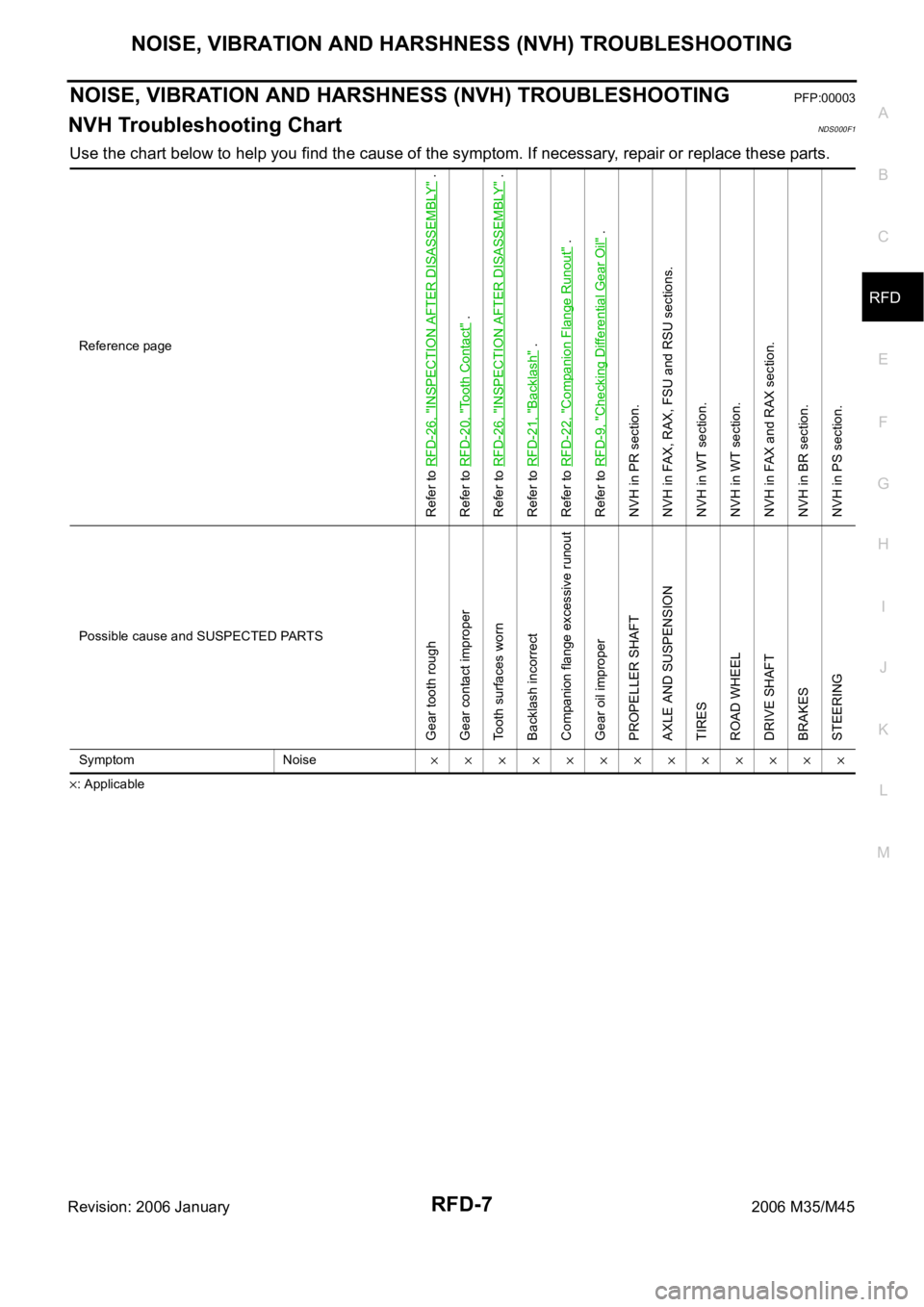
NOISE, VIBRATION AND HARSHNESS (NVH) TROUBLESHOOTINGPFP:00003
NVH Troubleshooting ChartNDS000F1
Use the chart below to help you find the cause of the symptom. If necessary, repair or replace these parts.
: ApplicableReference page
Refer to RFD-26, "
INSPECTION AFTER DISASSEMBLY
" .
Refer to RFD-20, "
Tooth Contact
" .
Refer to RFD-26, "
INSPECTION AFTER DISASSEMBLY
" .
Refer to RFD-21, "
Backlash
" .
Refer to RFD-22, "
Companion Flange Runout
" .
Refer to RFD-9, "
Checking Differential Gear Oil
" .
NVH in PR section.
NVH in FAX, RAX, FSU and RSU sections.
NVH in WT section.
NVH in WT section.
NVH in FAX and RAX section.
NVH in BR section.
NVH in PS section.
Possible cause and SUSPECTED PARTS
Gear tooth rough
Gear contact improper
Tooth surfaces worn
Backlash incorrect
Companion flange excessive runout
Gear oil improper
PROPELLER SHAFT
AXLE AND SUSPENSION
TIRES
ROAD WHEEL
DRIVE SHAFT
BRAKES
STEERING
Symptom Noise
Page 5053 of 5621
RFD-10
FRONT OIL SEAL
Revision: 2006 January2006 M35/M45
FRONT OIL SEALPFP:38189
Removal and InstallationNDS000F5
CAUTION:
Verify identification stamp of replacement frequency put in the lower part of gear carrier to determine
replacement for collapsible spacer when replacing front oil seal. Refer to RFD-10, "
IDENTIFICATION
STAMP OF REPLACEMENT FREQUENCY OF FRONT OIL SEAL" . If necessary collapsible spacer
replacement, remove final drive assembly and disassemble it to replace front oil seal and collapsible
spacer. Refer to RFD-16, "
Removal and Installation" and RFD-18, "Disassembly and Assembly" .
NOTE:
The reuse of collapsible spacer is prohibited in principle. However, it is reusable on a one-time basis
only in cases when replacing front oil seal.
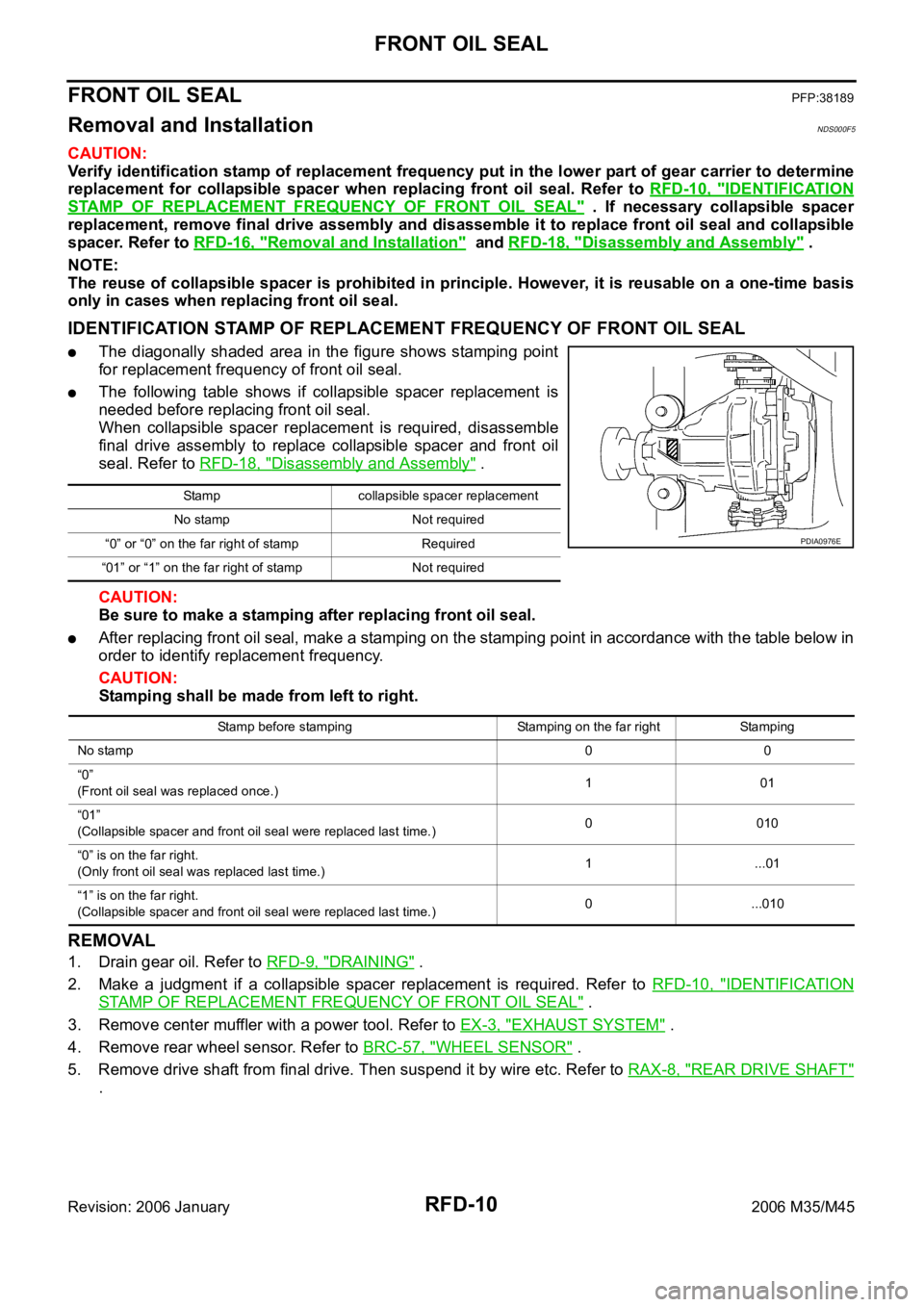
IDENTIFICATION STAMP OF REPLACEMENT FREQUENCY OF FRONT OIL SEAL
The diagonally shaded area in the figure shows stamping point
for replacement frequency of front oil seal.
The following table shows if collapsible spacer replacement is
needed before replacing front oil seal.
When collapsible spacer replacement is required, disassemble
final drive assembly to replace collapsible spacer and front oil
seal. Refer to RFD-18, "
Disassembly and Assembly" .
CAUTION:
Be sure to make a stamping after replacing front oil seal.
After replacing front oil seal, make a stamping on the stamping point in accordance with the table below in
order to identify replacement frequency.
CAUTION:
Stamping shall be made from left to right.
REMOVAL
1. Drain gear oil. Refer to RFD-9, "DRAINING" .
2. Make a judgment if a collapsible spacer replacement is required. Refer to RFD-10, "
IDENTIFICATION
STAMP OF REPLACEMENT FREQUENCY OF FRONT OIL SEAL" .
3. Remove center muffler with a power tool. Refer to EX-3, "
EXHAUST SYSTEM" .
4. Remove rear wheel sensor. Refer to BRC-57, "
WHEEL SENSOR" .
5. Remove drive shaft from final drive. Then suspend it by wire etc. Refer to RAX-8, "
REAR DRIVE SHAFT"
.
Stamp collapsible spacer replacement
No stamp Not required
“0” or “0” on the far right of stamp Required
“01” or “1” on the far right of stamp Not required
PDIA0976E
Stamp before stamping Stamping on the far right Stamping
No stamp00
“0”
(Front oil seal was replaced once.)101
“01”
(Collapsible spacer and front oil seal were replaced last time.)0 010
“0” is on the far right.
(Only front oil seal was replaced last time.)1...01
“1” is on the far right.
(Collapsible spacer and front oil seal were replaced last time.)0 ...010
Page 5056 of 5621
FRONT OIL SEAL
RFD-13
C
E
F
G
H
I
J
K
L
MA
B
RFD
Revision: 2006 January2006 M35/M45
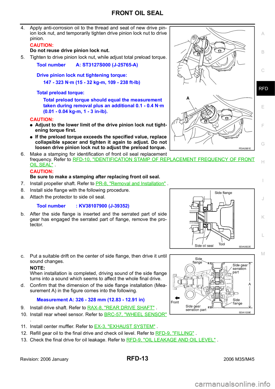
4. Apply anti-corrosion oil to the thread and seat of new drive pin-
ion lock nut, and temporarily tighten drive pinion lock nut to drive
pinion.
CAUTION:
Do not reuse drive pinion lock nut.
5. Tighten to drive pinion lock nut, while adjust total preload torque.
CAUTION:
Adjust to the lower limit of the drive pinion lock nut tight-
ening torque first.
If the preload torque exceeds the specified value, replace
collapsible spacer and tighten it again to adjust. Do not
loosen drive pinion lock nut to adjust the preload torque.
6. Make a stamping for identification of front oil seal replacement
frequency. Refer to RFD-10, "
IDENTIFICATION STAMP OF REPLACEMENT FREQUENCY OF FRONT
OIL SEAL" .
CAUTION:
Be sure to make a stamping after replacing front oil seal.
7. Install propeller shaft. Refer to PR-8, "
Removal and Installation" .
8. Install side flange with the following procedure.
a. Attach the protector to side oil seal.
b. After the side flange is inserted and the serrated part of side
gear has engaged the serrated part of flange, remove the pro-
tector.
c. Put a suitable drift on the center of side flange, then drive it until
sound changes.
NOTE:
When installation is completed, driving sound of the side flange
turns into a sound which seems to affect the whole final drive.
d. Confirm that the dimension of the side flange installation (Mea-
surement A) in the figure comes into the following.
9. Install drive shaft. Refer to RAX-8, "
REAR DRIVE SHAFT" .
10. Install rear wheel sensor. Refer to BRC-57, "
WHEEL SENSOR"
.
11. Install center muffler. Refer to EX-3, "
EXHAUST SYSTEM" .
12. Refill gear oil to the final drive and check oil level. Refer to RFD-9, "
FILLING" .
13. Check the final drive for oil leakage. Refer to RFD-9, "
OIL LEAKAGE AND OIL LEVEL" . Tool number A: ST3127S000 (J-25765-A)
Drive pinion lock nut tightening torque:
147 - 323 Nꞏm (15 - 32 kg-m, 109 - 238 ft-lb)
Total preload torque:
Total preload torque should equal the measurement
taken during removal plus an additional 0.1 - 0.4 Nꞏm
(0.01 - 0.04 kg-m, 1 - 3 in-lb).
Tool number : KV38107900 (J-39352)
PDIA0981E
SDIA0822E
Measurement A: 326 - 328 mm (12.83 - 12.91 in)
SDIA1039E
Page 5057 of 5621
RFD-14
SIDE OIL SEAL
Revision: 2006 January2006 M35/M45
SIDE OIL SEALPFP:33142
Removal and InstallationNDS000F6
REMOVAL
1. Remove center muffler with a power tool. Refer to EX-3, "EXHAUST SYSTEM" .
2. Remove rear wheel sensor. Refer to BRC-57, "
WHEEL SENSOR" .
3. Remove drive shaft from final drive with a power tool. Then suspend it by wire etc. Refer to RAX-8, "
REAR
DRIVE SHAFT" .
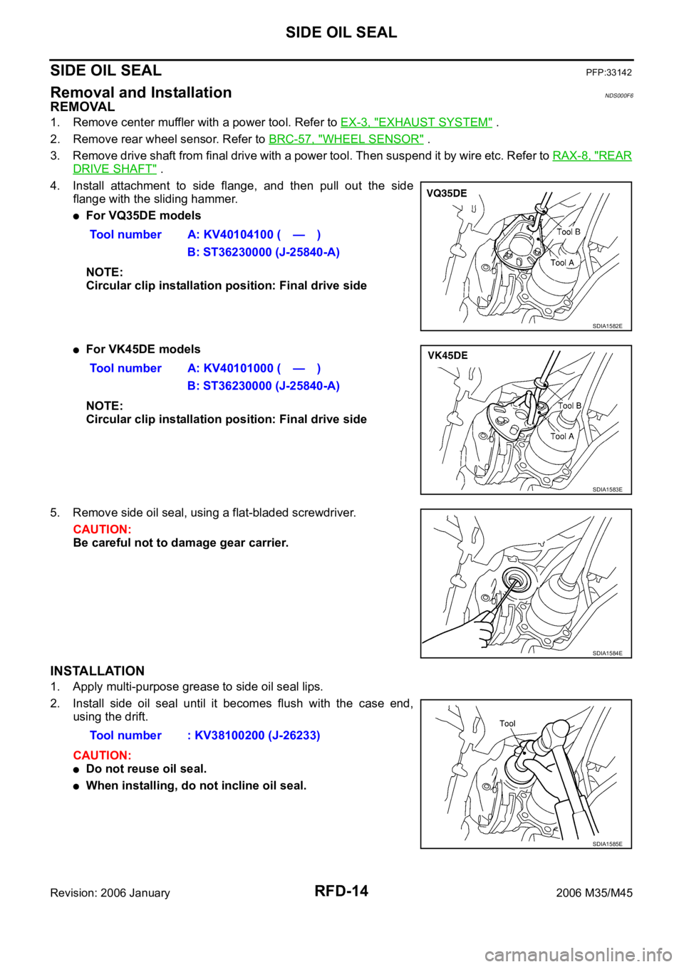
4. Install attachment to side flange, and then pull out the side
flange with the sliding hammer.
For VQ35DE models
NOTE:
Circular clip installation position: Final drive side
For VK45DE models
NOTE:
Circular clip installation position: Final drive side
5. Remove side oil seal, using a flat-bladed screwdriver.
CAUTION:
Be careful not to damage gear carrier.
INSTALLATION
1. Apply multi-purpose grease to side oil seal lips.
2. Install side oil seal until it becomes flush with the case end,
using the drift.
CAUTION:
Do not reuse oil seal.
When installing, do not incline oil seal.Tool number A: KV40104100 ( — )
B: ST36230000 (J-25840-A)
SDIA1582E
Tool number A: KV40101000 ( — )
B: ST36230000 (J-25840-A)
SDIA1583E
SDIA1584E
Tool number : KV38100200 (J-26233)
SDIA1585E
Page 5058 of 5621
SIDE OIL SEAL
RFD-15
C
E
F
G
H
I
J
K
L
MA
B
RFD
Revision: 2006 January2006 M35/M45
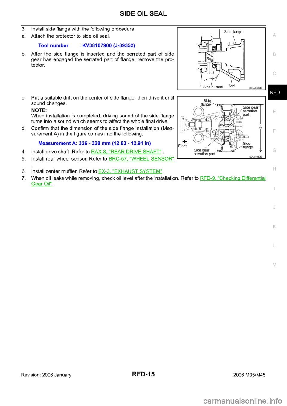
3. Install side flange with the following procedure.
a. Attach the protector to side oil seal.
b. After the side flange is inserted and the serrated part of side
gear has engaged the serrated part of flange, remove the pro-
tector.
c. Put a suitable drift on the center of side flange, then drive it until
sound changes.
NOTE:
When installation is completed, driving sound of the side flange
turns into a sound which seems to affect the whole final drive.
d. Confirm that the dimension of the side flange installation (Mea-
surement A) in the figure comes into the following.
4. Install drive shaft. Refer to RAX-8, "
REAR DRIVE SHAFT" .
5. Install rear wheel sensor. Refer to BRC-57, "
WHEEL SENSOR"
.
6. Install center muffler. Refer to EX-3, "
EXHAUST SYSTEM" .
7. When oil leaks while removing, check oil level after the installation. Refer to RFD-9, "
Checking Differential
Gear Oil" . Tool number : KV38107900 (J-39352)
SDIA0822E
Measurement A: 326 - 328 mm (12.83 - 12.91 in)
SDIA1039E
Page 5059 of 5621
RFD-16
REAR FINAL DRIVE ASSEMBLY
Revision: 2006 January2006 M35/M45
REAR FINAL DRIVE ASSEMBLYPFP:38300
Removal and InstallationNDS000F7
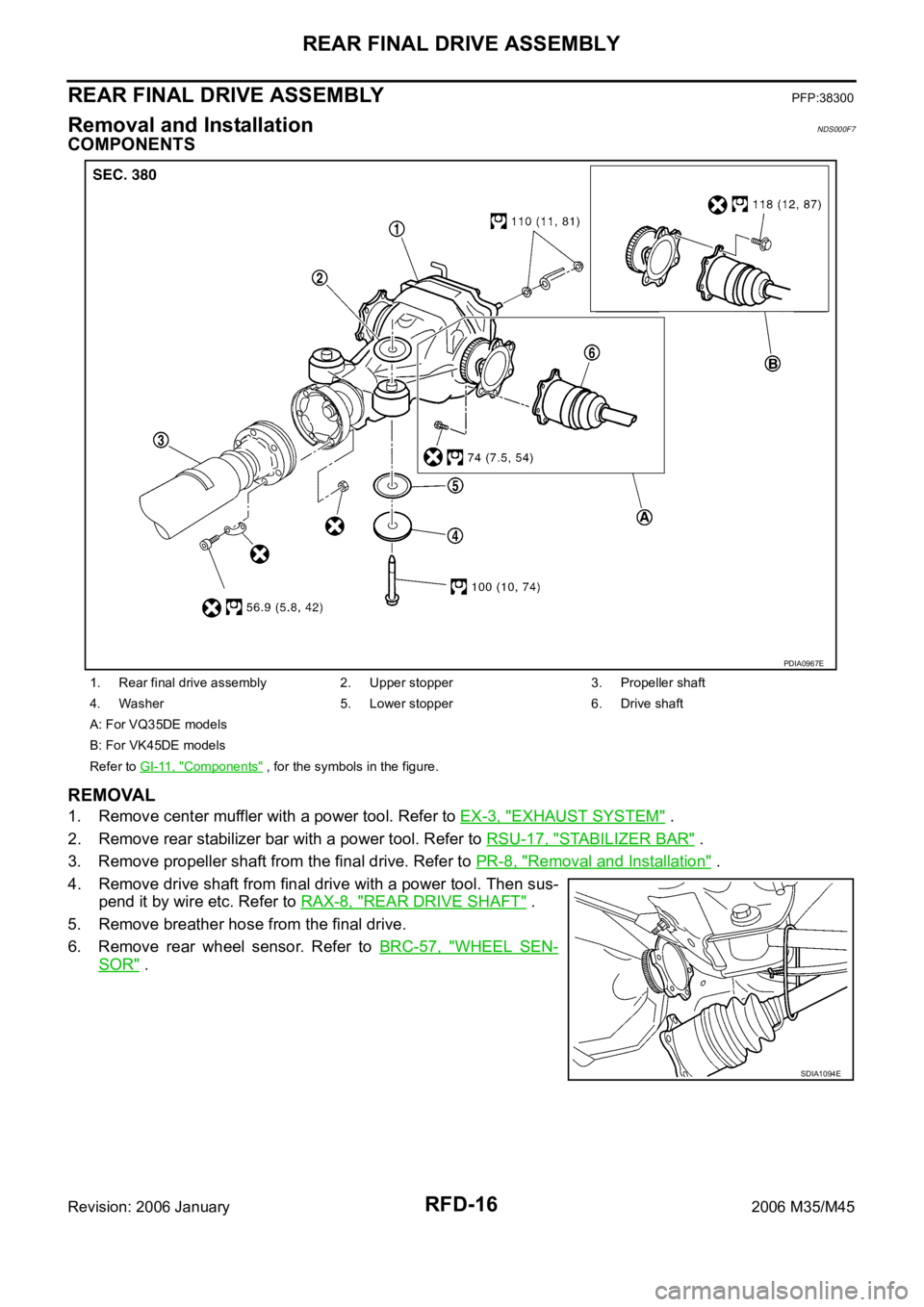
COMPONENTS
REMOVAL
1. Remove center muffler with a power tool. Refer to EX-3, "EXHAUST SYSTEM" .
2. Remove rear stabilizer bar with a power tool. Refer to RSU-17, "
STABILIZER BAR" .
3. Remove propeller shaft from the final drive. Refer to PR-8, "
Removal and Installation" .
4. Remove drive shaft from final drive with a power tool. Then sus-
pend it by wire etc. Refer to RAX-8, "
REAR DRIVE SHAFT" .
5. Remove breather hose from the final drive.
6. Remove rear wheel sensor. Refer to BRC-57, "
WHEEL SEN-
SOR" .
1. Rear final drive assembly 2. Upper stopper 3. Propeller shaft
4. Washer 5. Lower stopper 6. Drive shaft
A: For VQ35DE models
B: For VK45DE models
Refer to GI-11, "
Components" , for the symbols in the figure.
PDIA0967E
SDIA1094E
Page 5082 of 5621
RSU-1
REAR SUSPENSION
E SUSPENSION
CONTENTS
C
D
F
G
H
I
J
K
L
M
SECTION RSU
A
B
RSU
Revision: 2006 January2006 M35/M45
REAR SUSPENSION
PRECAUTIONS .......................................................... 2
Precautions .............................................................. 2
PREPARATION ........................................................... 3
Special Service Tools [SST] ..................................... 3
Commercial Service Tools ........................................ 3
NOISE, VIBRATION AND HARSHNESS (NVH)
TROUBLESHOOTING ................................................ 4
NVH Troubleshooting Chart ..................................... 4
REAR SUSPENSION ASSEMBLY ............................. 5
On-Vehicle Inspection and Service .......................... 5
SUSPENSION ARM BALL JOINT AXIAL END
PLAY INSPECTION .............................................. 5
SHOCK ABSORBER INSPECTION ..................... 5
Wheel Alignment Inspection ..................................... 5
DESCRIPTION ...................................................... 5
PRELIMINARY INSPECTION ............................... 5
GENERAL INFORMATION AND RECOMMEN-
DATIONS .............................................................. 5
THE ALIGNMENT PROCESS .............................. 6
CAMBER INSPECTION ........................................ 6
TOE-IN .................................................................. 6
Components ............................................................. 7
Removal and Installation .......................................... 8
REMOVAL ........................................................
..... 8
INSTALLATION ..................................................... 8
SHOCK ABSORBER ................................................ 10
Removal and Installation ........................................ 10
REMOVAL ........................................................
... 10
INSPECTION AFTER REMOVAL ....................... 10
INSTALLATION ................................................... 10
Disassembly and Assembly ................................... 10
DISASSEMBLY ................................................... 10
INSPECTION AFTER DISASSEMBLY ............... 10
ASSEMBLY .......................................................... 11SUSPENSION ARM .................................................. 12
Removal and Installation ........................................ 12
REMOVAL ........................................................
... 12
INSPECTION AFTER REMOVAL ....................... 12
INSTALLATION ................................................... 13
RADIUS ROD ............................................................ 14
Removal and Installation ........................................ 14
REMOVAL ........................................................
... 14
INSPECTION AFTER REMOVAL ....................... 14
INSTALLATION ................................................... 14
FRONT LOWER LINK .............................................. 15
Removal and Installation ........................................ 15
REMOVAL ........................................................
... 15
INSPECTION AFTER REMOVAL ....................... 15
INSTALLATION ................................................... 15
REAR LOWER LINK & COIL SPRING ..................
... 16
Removal and Installation ........................................ 16
REMOVAL ........................................................
... 16
INSPECTION AFTER REMOVAL ....................... 16
INSTALLATION ................................................... 16
STABILIZER BAR ..................................................... 17
Removal and Installation ........................................ 17
REMOVAL ........................................................
... 17
INSPECTION AFTER REMOVAL ....................... 17
INSTALLATION ................................................... 17
SERVICE DATA ........................................................ 18
Wheel Alignment (Unladen)* .................................. 18
Ball Joint ................................................................. 18
Wheelarch Height (Unladen*) ................................. 18
Page 5083 of 5621

RSU-2
PRECAUTIONS
Revision: 2006 January2006 M35/M45
PRECAUTIONSPFP:00001
PrecautionsNES000J2
When installing rubber bushings, final tightening must be carried out under unladen conditions with tires
on ground. Oil will shorten the life of rubber bushings. Be sure to wipe off any spilled oil.
–Unladen conditions mean that fuel, engine coolant and lubricant are full. Spare tire, jack, hand tools and
mats are in designated positions.
After servicing suspension parts, be sure to check wheel alignment.
Self-lock nuts are not reusable. Always use new ones when installing. Since new self-lock nuts are pre-
oiled, tighten as they are.
Page 5084 of 5621
![INFINITI M35 2006 Factory Service Manual PREPARATION
RSU-3
C
D
F
G
H
I
J
K
L
MA
B
RSU
Revision: 2006 January2006 M35/M45
PREPARATIONPFP:00002
Special Service Tools [SST]NES000J3
The actual shapes of Kent-Moore tools may differ from those of INFINITI M35 2006 Factory Service Manual PREPARATION
RSU-3
C
D
F
G
H
I
J
K
L
MA
B
RSU
Revision: 2006 January2006 M35/M45
PREPARATIONPFP:00002
Special Service Tools [SST]NES000J3
The actual shapes of Kent-Moore tools may differ from those of](/img/42/57023/w960_57023-5083.png)
PREPARATION
RSU-3
C
D
F
G
H
I
J
K
L
MA
B
RSU
Revision: 2006 January2006 M35/M45
PREPARATIONPFP:00002
Special Service Tools [SST]NES000J3
The actual shapes of Kent-Moore tools may differ from those of special service tools illustrated here.
Commercial Service ToolsNES000J4
Tool number
(Kent-Moore No.)
Tool nameDescription
ST3127S000
(See J25742-1)
Preload Gauge
1. GG91030000
(J25765)
Torque wrench
2. HT62940000
(—)
Socket adapter
3. HT62900000
(—)
Socket adapterMeasuring rotating torque of ball joint
NT124
Tool nameDescription
Power tool
Removing wheel nuts
Removing brake caliper assembly
Removing rear suspension component
parts
PBIC0190E