Motor INFINITI M35 2006 Factory Service Manual
[x] Cancel search | Manufacturer: INFINITI, Model Year: 2006, Model line: M35, Model: INFINITI M35 2006Pages: 5621, PDF Size: 65.56 MB
Page 5116 of 5621
![INFINITI M35 2006 Factory Service Manual PRE-CRASH SEAT BELT
SB-17
C
D
E
F
G
I
J
K
L
MA
B
SB
Revision: 2006 January2006 M35/M45
Ignition Power Supply Circuit CheckNHS00089
1. CHECK FUSE
Check 10A fuse [No.15, located in fuse block (J/B)].
NO INFINITI M35 2006 Factory Service Manual PRE-CRASH SEAT BELT
SB-17
C
D
E
F
G
I
J
K
L
MA
B
SB
Revision: 2006 January2006 M35/M45
Ignition Power Supply Circuit CheckNHS00089
1. CHECK FUSE
Check 10A fuse [No.15, located in fuse block (J/B)].
NO](/img/42/57023/w960_57023-5115.png)
PRE-CRASH SEAT BELT
SB-17
C
D
E
F
G
I
J
K
L
MA
B
SB
Revision: 2006 January2006 M35/M45
Ignition Power Supply Circuit CheckNHS00089
1. CHECK FUSE
Check 10A fuse [No.15, located in fuse block (J/B)].
NOTE:
Refer to SB-3, "
Component Parts and Harness Connector Location" .
OK or NG
OK >> GO TO 2.
NG >> If fuse is blown out, be sure to eliminate cause of malfunction before installing new fuse. Refer to
PG-3, "
POWER SUPPLY ROUTING CIRCUIT" .
2. CHECK IGNITION POWER SUPPLY CIRCUIT
1. Disconnect pre-crash seat belt control unit connector.
2. Turn ignition switch ON.
3. Check voltage between pre-crash seat belt control unit harness
connector and ground.
OK or NG
OK >> Ignition power supply circuit is OK.
NG >> Check pre-crash seat belt control unit ignition power supply circuit harness.
Motor Power Supply and Ground Circuit Check [B2454]NHS0008A
1. CHECK FUSE
Check 30A fusible link (letter G , located in the fuse and fusible link box).
NOTE:
Refer to SB-3, "
Component Parts and Harness Connector Location" .
OK or NG
OK >> GO TO 2.
NG >> If fuse is blown out, be sure to eliminate cause of malfunction before installing new fuse. Refer to
PG-3, "
POWER SUPPLY ROUTING CIRCUIT" .
Terminal
Voltage (V)
(Approx.) (+)
(–) Pre-crash seat
belt control unit
connectorTerminal
B142 13 Ground Battery voltage
PHIA1126E
Page 5117 of 5621

SB-18
PRE-CRASH SEAT BELT
Revision: 2006 January2006 M35/M45
2. CHECK MOTOR POWER SUPPLY CIRCUIT 1
With CONSULT-II
Select “SELF-DIAG RESULTS” and then make sure the “MOTOR
PWR SUP CIRC” is displayed.
Without CONSULT-II
When CONSULT-II is not used, omit this inspection, and then GO TO 3.
Displayed B2454?
Yes >> GO TO 3.
No >> Motor power supply system is normal.
3. CHECK MOTOR POWER SUPPLY CIRCUIT 2
1. Disconnect pre-crash seat belt control unit connector.
2. Check voltage between pre-crash seat belt control unit harness
connector and ground.
OK or NG
OK >> GO TO 4.
NG >> Repair or replace harness.
4. CHECK PRE-CRASH SEAT BELT CONTROL UNIT GROUND CIRCUIT
1. Disconnect pre-crash seat belt control unit connector.
2. Check continuity between pre-crash seat belt control unit har-
ness connector and ground.
OK or NG
OK >> Motor power supply and ground circuit is OK.
NG >> Repair or replace harness.
CONSULT-II display CONSULT-II display code
NO DTC –
MOTOR PWR SUP CIRC B2454
PHIA0770E
Terminal
Voltage (V)
(Approx.) (+)
(–) Pre-crash seat
belt control unit
connectorTerminal
B142 2 Ground Battery voltage
PHIA1127E
Terminal
Continuity Pre-crash seat
belt control unit
connectorTerminal
Ground
B1425
Ye s
26
PHIA1128E
Page 5124 of 5621

PRE-CRASH SEAT BELT
SB-25
C
D
E
F
G
I
J
K
L
MA
B
SB
Revision: 2006 January2006 M35/M45
5. CHECK BRAKE PEDAL STROKE SENSOR
Check continuity between brake pedal stroke sensor while perform-
ing brake operation.
OK or NG
OK >> Check harness connection.
If it is OK, replace pre-crash seat belt control unit.
If it is NG, repair or replace malfunction part.
NG >> Replace brake pedal stroke sensor.
Pre-Crash Seat Belt Motor LH Circuit Check [B2452]NHS0008E
1. CHECK LH SEAT BELT MOTOR CIRCUIT
With CONSULT-II
Select “SELF-DIAG RESULTS” of CONSULT-II, and then make sure
that “SB MOTOR LH CIRC” is displayed.
Without CONSULT-II
When CONSULT-II is not used, omit this inspection, and then GO TO 2.
Displayed B2452?
Ye s > > G O T O 2 .
No >> Pre-crash seat belt motor LH circuit is OK.
Brake pedal stroke
sensor connectorTerminal ConditionResistance
(K)
(Approx.)
E125 21
Brake released
depressed1.0 0.2
30.2
1.0
PHIA1137E
CONSULT-II display CONSULT-II display code
NO DTC –
SB MOTOR LH CIRC B2452
PHIA0768E
Page 5125 of 5621

SB-26
PRE-CRASH SEAT BELT
Revision: 2006 January2006 M35/M45
2. CHECK LH SEAT BELT MOTOR HARNESS
1. Turn the ignition switch OFF.
2. Disconnect pre-crash seat belt control unit connector and pre-crash seat belt motor LH connector.
3. Check continuity between pre-crash seat belt control unit har-
ness connector and pre-crash seat belt motor LH harness con-
nector.
4. Check continuity between pre-crash seat belt control unit har-
ness connector and ground.
OK or NG
OK >> GO TO 3.
NG >> Repair or replace harness.
3. CHECK SEAT BELT MOTOR
Check continuity between pre-crash seat belt motor LH.
OK or NG
OK >> Replace pre-crash seat belt control unit.
NG >> Replace pre-crash seat belt motor LH.
AB
Continuity Pre-crash seat
belt control unit
connectorTe r m i n a lPre-crash seat
belt motor LH
connectorTerminal
B1424
B321
Ye s
62
A
GroundContinuity
Pre-crash seat belt
control unit connectorTerminal
B1424
No
6
PHIA1138E
Pre-crash seat belt
motor LH connectorTerminal Continuity
B32 1 2 Yes
PHIA1139E
Page 5126 of 5621
![INFINITI M35 2006 Factory Service Manual PRE-CRASH SEAT BELT
SB-27
C
D
E
F
G
I
J
K
L
MA
B
SB
Revision: 2006 January2006 M35/M45
Pre-Crash Seat Belt Motor RH Circuit Check [B2451]NHS0008F
1. CHECK RH SEAT BELT MOTOR CIRCUIT
With CONSULT-II
S INFINITI M35 2006 Factory Service Manual PRE-CRASH SEAT BELT
SB-27
C
D
E
F
G
I
J
K
L
MA
B
SB
Revision: 2006 January2006 M35/M45
Pre-Crash Seat Belt Motor RH Circuit Check [B2451]NHS0008F
1. CHECK RH SEAT BELT MOTOR CIRCUIT
With CONSULT-II
S](/img/42/57023/w960_57023-5125.png)
PRE-CRASH SEAT BELT
SB-27
C
D
E
F
G
I
J
K
L
MA
B
SB
Revision: 2006 January2006 M35/M45
Pre-Crash Seat Belt Motor RH Circuit Check [B2451]NHS0008F
1. CHECK RH SEAT BELT MOTOR CIRCUIT
With CONSULT-II
Select SELF-DIAG RESULTS” of CONSULT-II, and then make sure
that “SB MOTOR RH CIRC” is displayed.
Without CONSULT-II
When CONSULT-II is not used, omit this inspection, and then GO TO 2.
Displayed B2451?
Ye s > > G O T O 2 .
No >> Pre-crash seat belt motor RH circuit is OK.
2. CHECK RH SEAT BELT MOTOR HARNESS
1. Turn the ignition switch OFF.
2. Disconnect pre-crash seat belt control unit connector and pre-crash seat belt motor RH connector.
3. Check continuity between pre-crash seat belt control unit har-
ness connector and pre-crash seat belt motor RH harness con-
nector.
4. Check continuity between pre-crash seat belt control unit har-
ness connector and ground.
OK or NG
OK >> GO TO 3.
NG >> Repair or replace harness.
CONSULT-II display CONSULT-II display code
NO DTC –
SB MOTOR RH CIRC B2451
PHIA0767E
AB
Continuity Pre-crash seat
belt control unit
connectorTerminalPre-crash seat
belt motor RH
connectorTerminal
B1421
B82
Ye s
3 1
A
GroundContinuity
Pre-crash seat belt
control unit connectorTerminal
B1421
No
3
PHIA1140E
Page 5127 of 5621

SB-28
PRE-CRASH SEAT BELT
Revision: 2006 January2006 M35/M45
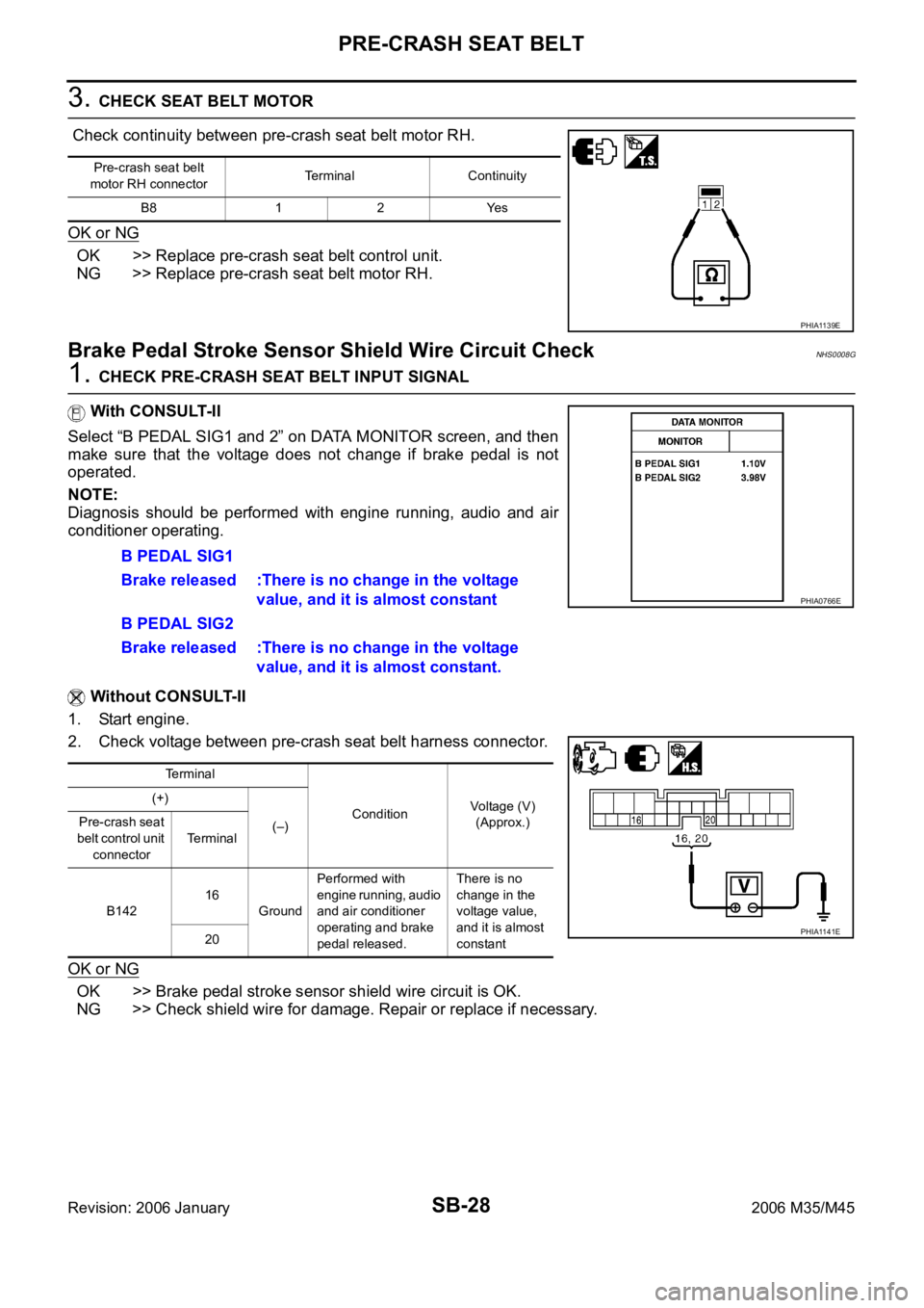
3. CHECK SEAT BELT MOTOR
Check continuity between pre-crash seat belt motor RH.
OK or NG
OK >> Replace pre-crash seat belt control unit.
NG >> Replace pre-crash seat belt motor RH.
Brake Pedal Stroke Sensor Shield Wire Circuit CheckNHS0008G
1. CHECK PRE-CRASH SEAT BELT INPUT SIGNAL
With CONSULT-II
Select “B PEDAL SIG1 and 2” on DATA MONITOR screen, and then
make sure that the voltage does not change if brake pedal is not
operated.
NOTE:
Diagnosis should be performed with engine running, audio and air
conditioner operating.
Without CONSULT-II
1. Start engine.
2. Check voltage between pre-crash seat belt harness connector.
OK or NG
OK >> Brake pedal stroke sensor shield wire circuit is OK.
NG >> Check shield wire for damage. Repair or replace if necessary.
Pre-crash seat belt
motor RH connectorTerminal Continuity
B8 1 2 Yes
PHIA1139E
B PEDAL SIG1
Brake released :There is no change in the voltage
value, and it is almost constant
B PEDAL SIG2
Brake released :There is no change in the voltage
value, and it is almost constant.
Terminal
ConditionVoltage (V)
(Approx.) (+)
(–) Pre-crash seat
belt control unit
connectorTerminal
B14216
GroundPerformed with
engine running, audio
and air conditioner
operating and brake
pedal released.There is no
change in the
voltage value,
and it is almost
constant 20
PHIA0766E
PHIA1141E
Page 5147 of 5621

SC-10
STARTING SYSTEM
Revision: 2006 January2006 M35/M45
STARTING SYSTEM PFP:00011
System Description NKS003NI
Power is supplied at all times
through 15A fuse (No. 78, located in the IPDM E/R)
to CPU of IPDM E/R,
through 15A fuse (No. 71, located in the IPDM E/R)
to CPU of IPDM E/R.
Ground is supplied
to IPDM E/R terminals 38 and 51
from grounds E22 and E43.
When the selector lever in the P or N position, power is supplied
from TCM, and through A/T assembly terminal 9
to IPDM E/R terminal 53.
And then provided that IPDM E/R receives a starter relay ON signal with CAN communication, starter relay is
energized.
With the ignition switch in the START position, power is supplied
through IPDM E/R terminal 3
to starter motor terminal 1.
The starter motor plunger closes and provides a closed circuit between the battery and starter motor. The
starter motor is grounded to the engine block. With power and ground supplied, cranking occurs and the
engine starts.
Page 5152 of 5621

STARTING SYSTEM
SC-15
C
D
E
F
G
H
I
J
L
MA
B
SC
Revision: 2006 January2006 M35/M45
DIAGNOSTIC PROCEDURE 1
Check “B” Terminal Circuit
CAUTION:
Perform diagnosis under the condition that engine cannot start by the following procedure.
1. Remove fuel pump fuse.
2. Crank or start the engine (where possible) until the fuel pressure is released.
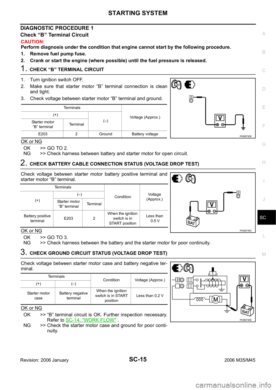
1. CHECK “B” TERMINAL CIRCUIT
1. Turn ignition switch OFF.
2. Make sure that starter motor “B” terminal connection is clean
and tight.
3. Check voltage between starter motor “B” terminal and ground.
OK or NG
OK >> GO TO 2.
NG >> Check harness between battery and starter motor for open circuit.
2. CHECK BATTERY CABLE CONNECTION STATUS (VOLTAGE DROP TEST)
Check voltage between starter motor battery positive terminal and
starter motor “B” terminal.
OK or NG
OK >> GO TO 3.
NG >> Check harness between the battery and the starter motor for poor continuity.
3. CHECK GROUND CIRCUIT STATUS (VOLTAGE DROP TEST)
Check voltage between starter motor case and battery negative ter-
minal.
OK or NG
OK >> “B” terminal circuit is OK. Further inspection necessary.
Refer to SC-14, "
WORK FLOW" .
NG >> Check the starter motor case and ground for poor conti-
nuity.
Terminals
Voltage (Approx.) (+)
(–)
Starter motor
“B” terminalTerminal
E203 2 Ground Battery voltage
PKIB8793E
Terminals
ConditionVoltage
(Approx.)
(+)(–)
Starter motor
“B” terminalTerminal
Battery positive
terminalE203 2 When the ignition
switch is in
START positionLess than
0.5 V
PKIB8794E
Terminals
Condition Voltage (Approx.)
(+) (–)
Starter motor
caseBattery negative
terminalWhen the ignition
switch is in START
positionLess than 0.2 V
PKIB8795E
Page 5153 of 5621

SC-16
STARTING SYSTEM
Revision: 2006 January2006 M35/M45
DIAGNOSTIC PROCEDURE 2
Check “S” Connector Circuit
CAUTION:
Perform diagnosis under the condition that engine cannot start by the following procedure.
1. Remove fuel pump fuse.
2. Crank or start the engine (where possible) until the fuel pressure is released.
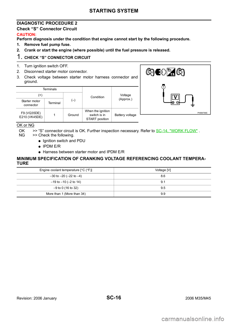
1. CHECK “S” CONNECTOR CIRCUIT
1. Turn ignition switch OFF.
2. Disconnect starter motor connector.
3. Check voltage between starter motor harness connector and
ground.
OK or NG
OK >> “S” connector circuit is OK. Further inspection necessary. Refer to SC-14, "WORK FLOW" .
NG >> Check the following.
Ignition switch and PDU
IPDM E/R
Harness between starter motor and IPDM E/R
MINIMUM SPECIFICATION OF CRANKING VOLTAGE REFERENCING COOLANT TEMPERA-
TURE
Te r m i n a l s
ConditionVoltage
(Approx.) (+)
(–)
Starter motor
connectorTe r m i n a l
F9 (VQ35DE)
E210 (VK45DE)1 GroundWhen the ignition
switch is in
START positionBattery voltage
PKIB8796E
Engine coolant temperature [C (F)] Voltage [V]
30 to 20 (22 to 4) 8.6
19 to 10 (2 to 14) 9.1
9 to 0 (16 to 32) 9.5
More than 1 (More than 34) 9.9
Page 5154 of 5621

STARTING SYSTEM
SC-17
C
D
E
F
G
H
I
J
L
MA
B
SC
Revision: 2006 January2006 M35/M45
Removal and Installation NKS003NL
VQ35DE ENGINE MODELS (2WD)
Removal
1. Disconnect the battery cable from the negative terminal.
2. Remove engine front and rear undercover, using power tools.
3. Remove “B” terminal nut (1).
4. Disconnect “S” connector (2).
5. Remove starter motor mounting bolts (A), using power tools.
6. Remove starter motor downward from the vehicle.
Installation
Installation is the reverse order of removal.
CAUTION:
Be sure to tighten “B” terminal nut carefully.
1. Starter motor mounting bolt 2. Harness clip bracket 3. “S” connector
4. “B” terminal nut 5. “B” terminal harness 6. Starter motor
7. Oil pan : Nꞏm (kg-m, ft-lb) : Nꞏm (kg-m, in-lb)
: Engine front
PKIB8799E
PKIB8800E