Motor INFINITI M35 2006 Factory Service Manual
[x] Cancel search | Manufacturer: INFINITI, Model Year: 2006, Model line: M35, Model: INFINITI M35 2006Pages: 5621, PDF Size: 65.56 MB
Page 5034 of 5621

SUNROOF
RF-21
C
D
E
F
G
H
J
K
L
MA
B
RF
Revision: 2006 January2006 M35/M45
Sunroof Switch CheckNIS00240
1. SUNROOF SWITCH INPUT SIGNAL CHECK
1. Turn ignition switch ON.
2. Check voltage between sunroof motor assembly connector and ground.
OK or NG
OK >> Sunroof switch system is OK.
NG >> GO TO 2.
2. SUNROOF SWITCH CIRCUIT CHECK
1. Turn ignition switch OFF.
2. Disconnect sunroof motor assembly and sunroof switch connector.
3. Check continuity between sunroof motor assembly connector and sunroof switch connector.
4. Check continuity between sunroof motor assembly connector
and ground.
OK or NG
OK >> GO TO 3.
NG >> Repair or replace harness.
Sunroof
motor
assembly
connectorTerminals
ConditionVoltage (V)
(Approx.)
(+) (–)
M1864
GroundSunroof switch is operated
TILT DOWN or SLIDE OPEN0
Other than above Battery voltage
11Sunroof switch is operated
TILT UP or SLIDE CLOSE0
Other than above Battery voltage
PIIB5908E
AB
Continuity
Sunroof motor
assembly connectorTerminalSunroof switch
connectorTerminal
M1864
R531
Ye s
11 3
A
GroundContinuity
Sunroof motor
assembly connectorTerminal
M1864
No
11
PIIB5909E
Page 5035 of 5621

RF-22
SUNROOF
Revision: 2006 January2006 M35/M45
3. SUNROOF SWITCH GROUND CIRCUIT CHECK
Check continuity between sunroof switch connector and ground.
OK or NG
OK >> GO TO 4.
NG >> Repair or replace harness.
4. SUNROOF SWITCH GROUND CIRCUIT CHECK
Check continuity between sunroof motor connector and sunroof switch connector.
OK or NG
OK >> GO TO 5.
NG >> Repair or replace harness.
5. SUNROOF SWITCH CHECK
Check continuity between sunroof switch terminals.
OK or NG
OK >> Replace sunroof motor assembly.
NG >> Replace sunroof switch.
Sunroof switch
connectorTerminal
GroundContinuity
R53 2 Yes
PIIB5910E
AB
Continuity
Sunroof switch
connectorTerminalSunroof motor
assembly connectorTerminal
R53 2 M186 9 Yes
PIIB5911E
Terminals Condition Continuity
1
2Sunroof switch is operated
TILT DOWN or SLIDE OPENYe s
Other than above No
3Sunroof switch is operated
TILT UP or SLIDE CLOSEYe s
Other than above No
PIIB5907E
Page 5038 of 5621

SUNROOF
RF-25
C
D
E
F
G
H
J
K
L
MA
B
RF
Revision: 2006 January2006 M35/M45
Fitting AdjustmentNIS00242
RID WEATHERSTRIP OVERLAP ADJUSTMENT AND SURFACE MISMATCH ADJUSTMENT
1. Tilt up glass lid then remove side trim.
2. After loosening glass lid from bolts (left and right), tilt down glass lid.
3. Adjust glass lid from outside of vehicle so it resembles “A–A” “B–B” "C–C" as shown in the figure.
4. To prevent glass lid from moving after adjustment, first tighten the bolts of front left, and then tighten the
bolts of rear right.
5. Tighten remaining bolts, being careful to prevent glass lid from moving.
6. Tilt glass lid up and down several times to check that it moves smoothly.
Removal and InstallationNIS00243
After any adjustment, check sunroof operation and glass lid alignment.
Handle finisher plate and glass lid with care so not to cause damage.
It is desirable for easy installation to mark each point before removal.
CAUTION:
Always work with a helper.
Fully close the glass lid assembly, before removal, then do not operate sunroof motor assembly
after removal.
PIIB3117J
ab
A–A 1.4
0.8 mm (0.055 0.031 in) 0 1.5 mm (0 0.059 in)
B–B 1.2
0.8 mm (0.047 0.031 in) 0 1.5 mm (0 0.059 in)
C–C 1.4
0.8 mm (0.055 0.031 in) 0 1.5 mm (0 0.059 in)
Page 5040 of 5621

SUNROOF
RF-27
C
D
E
F
G
H
J
K
L
MA
B
RF
Revision: 2006 January2006 M35/M45
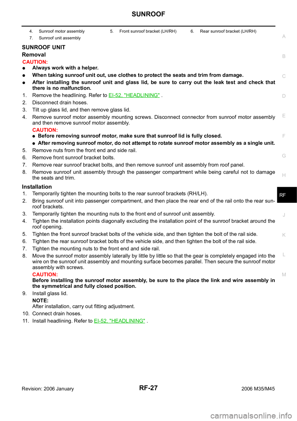
SUNROOF UNIT
Removal
CAUTION:
Always work with a helper.
When taking sunroof unit out, use clothes to protect the seats and trim from damage.
After installing the sunroof unit and glass lid, be sure to carry out the leak test and check that
there is no malfunction.
1. Remove the headlining. Refer to EI-52, "
HEADLINING" .
2. Disconnect drain hoses.
3. Tilt up glass lid, and then remove glass lid.
4. Remove sunroof motor assembly mounting screws. Disconnect connector from sunroof motor assembly
and then remove sunroof motor assembly.
CAUTION:
Before removing sunroof motor, make sure that sunroof lid is fully closed.
After removing sunroof motor, do not attempt to rotate sunroof motor assembly as a single unit.
5. Remove nuts from the front end and side rail.
6. Remove front sunroof bracket bolts.
7. Remove rear sunroof bracket bolts, and then remove sunroof unit assembly from roof panel.
8. Remove sunroof unit assembly through the passenger compartment while being careful not to damage
the seats and trim.
Installation
1. Temporarily tighten the mounting bolts to the rear sunroof brackets (RH/LH).
2. Bring sunroof unit into passenger compartment, and then place the rear end of the rail onto the rear sun-
roof brackets.
3. Temporarily tighten the mounting nuts to the front end of sunroof unit assembly.
4. Tighten the installation points diagonally excluding the installation point of the sunroof bracket around the
roof opening.
5. Tighten the front sunroof bracket bolts of the vehicle side, and then tighten the bolt of the rail side.
6. Tighten the rear sunroof bracket bolts of the vehicle side, and then tighten the bolt of the rail side.
7. Tighten the mounting nuts to the front end and side rail.
8. Move the sunroof motor assembly laterally by little by little so that the gear is completely engaged into the
wire on the sunroof unit assembly and mounting surface becomes parallel. Then secure the sunroof motor
assembly with screws.
CAUTION:
Before installing the sunroof motor assembly, be sure to the place the link and wire assembly in
the symmetrical and fully closed position.
9. Install glass lid.
NOTE:
After installation, carry out fitting adjustment.
10. Connect drain hoses.
11. Install headlining. Refer to EI-52, "
HEADLINING" .
4. Sunroof motor assembly 5. Front sunroof bracket (LH/RH) 6. Rear sunroof bracket (LH/RH)
7. Sunroof unit assembly
Page 5100 of 5621

SB-1
SEAT BELTS
H RESTRAINTS
CONTENTS
C
D
E
F
G
I
J
K
L
M
SECTION SB
A
B
SB
Revision: 2006 January2006 M35/M45
SEAT BELTS
PRECAUTIONS .......................................................... 2
Precautions for Supplemental Restraint System
(SRS) “AIR BAG” and “SEAT BELT PRE-TEN-
SIONER” .................................................................. 2
Precaution for Seat Belt Service .............................. 2
AFTER A COLLISION ........................................... 2
PRE-CRASH SEAT BELT .......................................... 3
Component Parts and Harness Connector Location ..... 3
System Description .................................................. 3
FUNCTION DESCRIPTION .................................. 4
FAIL-SAFE MODE ................................................ 4
CAN Communication System Description ................ 5
CAN Communication Unit ........................................ 5
Schematic ................................................................ 6
Wiring Diagram — PSB — ....................................... 7
Terminals and Reference Value for Pre-Crash Seat
Belt Control Unit ..................................................... 13
Work Flow .............................................................. 13
CONSULT-II Function (PRECRASH SEATBELT) ... 14
CONSULT-II INSPECTION PROCEDURE ......... 14
HOW TO READ SELF-DIAGNOSTIC RESULTS ... 15
SELF-DIAGNOSTIC RESULTS ITEM CHART ... 15
DATA MONITOR ITEM CHART .......................... 15
Preliminary Check .................................................. 16
PRE-CRASH SEAT BELT OPERATION
INSPECTION ...................................................... 16
Diagnoses Symptom Chart .................................... 16
Check CAN Communication System Inspection
[U1000] ................................................................... 16
Ignition Power Supply Circuit Check ...................... 17
Motor Power Supply and Ground Circuit Check
[B2454] ................................................................... 17
Seat Belt Buckle Switch (Driver Side) Circuit Check ... 19
Seat Belt Buckle Switch (Passenger Side) Circuit
Check ..................................................................... 21
Brake Pedal Stroke Sensor Circuit Check [B2453] ... 22
Pre-Crash Seat Belt Motor LH Circuit Check [B2452]
... 25
Pre-Crash Seat Belt Motor RH Circuit Check [B2451] ................................................................... 27
Brake Pedal Stroke Sensor Shield Wire Circuit
Check ..................................................................... 28
Removal and Installation of Pre-Crash Seat Belt
Control Unit ............................................................. 29
REMOVAL ........................................................
... 29
INSTALLATION ................................................... 29
SEAT BELTS ............................................................. 30
System Description ................................................. 30
SEAT BELT WARNING CHIME ........................... 30
SEAT BELT WARNING LAMP ............................. 30
Removal and Installation of Front Seat Belt ........... 30
REMOVAL OF SEAT BELT RETRACTOR .......... 30
INSTALLATION OF SEAT BELT RETRACTOR ... 31
REMOVAL OF SEAT BELT BUCKLE .................. 31
INSTALLATION OF SEAT BELT BUCKLE .......
... 31
Removal and Installation of Rear Seat Belt ............ 32
REMOVAL OF SEAT BELT RETRACTOR .......... 32
INSTALLATION OF SEAT BELT RETRACTOR ... 32
REMOVAL OF SEAT BELT BUCKLE .................. 32
INSTALLATION OF SEAT BELT BUCKLE .......... 33
Seat Belt Inspection ................................................ 33
AFTER A COLLISION ......................................... 33
PRELIMINARY CHECKS .................................... 33
SEAT BELT RETRACTOR ON-VEHICLE
CHECK ................................................................ 34
SEAT BELT RETRACTOR OFF-VEHICLE
CHECK (FRONT SEAT BELT) ............................ 35
SEAT BELT RETRACTOR OFF-VEHICLE
CHECK (REAR SEAT BELT) ............................... 35
LATCH (LOWER ANCHORS AND TETHER FOR
CHILDREN) SYSTEM ............................................... 36
Removal and Installation ........................................ 36
REMOVAL ........................................................
... 36
INSTALLATION ................................................... 36
TOP TETHER STRAP CHILD RESTRAINT ............. 37
Removal and Installation ........................................ 37
REMOVAL ........................................................
... 37
INSTALLATION ................................................... 37
Page 5102 of 5621

PRE-CRASH SEAT BELT
SB-3
C
D
E
F
G
I
J
K
L
MA
B
SB
Revision: 2006 January2006 M35/M45
PRE-CRASH SEAT BELTPFP:98845
Component Parts and Harness Connector LocationNHS0007X
System DescriptionNHS0007Y
Pre-crash seat belt system is adapted to front seat belts RH/LH.
When the pre-crash seat belt control unit judges the emergency braking operation, it gives the sense of
security by the motor built into the pre-crash seat belt retracting the shoulder belt and suppressing the
crew's posture change. Also, it eases the damage of the collision.
PHIA1123E
1. Fuse block (J/B) 2.Fuse, fusible link and relay block
(J/B)3.Pre-crash seat belt control unit B142
(View with the trunk side finisher LH
removed)
4.Brake pedal stroke sensor E125
(View with the instrument driver
lower panel removed)5.Pre-crash seat belt motor B32 (LH),
B8 (RH)
(View with the center pillar lower
garnish removed)6.Seat belt buckle switch B203 (driver
seat) B253 (passenger seat)
Page 5103 of 5621

SB-4
PRE-CRASH SEAT BELT
Revision: 2006 January2006 M35/M45
FUNCTION DESCRIPTION
Operation condition
Pre-crash seat belt operates under the following conditions.
Operation prohibition condition
If operation condition is satisfied, pre-crash seat belt does not operate under the following conditions.
*1 :When pre-crash seat belt doesn't operate after it continuously operates 3 times or more, operation can be performed again by stop-
ping operation for approximately 7 minutes.
*
2 : Refer to SB-4, "FAIL-SAFE MODE" for details of fail-safe mode.
FAIL-SAFE MODE
When a malfunction occurs in the following system, the pre-crash seat belt function is controlled according to
the malfunctioning parts.
Also, seat belt warning lamp blinks with fastening driver seat belt when the following malfunction occurs.
Seat Belt Warning Lamp Illumination Pattern
NOTE:
The seat belt warning lamp illumination system shown above operates only when the air bag system does not
turn on the seat belt warning lamp. The air bag system turns on the seat belt warning lamp, depending on the
conditions of passenger being on and the passenger seat belt fastening.
ConditionWhen the brake pedal is depressed more than a certain extent
When operation prohibition condition is not satisfied
Condition
When seat belt is not fastened (Only the seat belt that is not fastened does not operate.)
When vehicle is moving backwards
When the vehicle speed is 15 km/h (9 MPH) or less
When pre-crash seat belt continuously operates 3 times or more *1
At fail-safe condition *2
Malfunctioning parts Control contents
Brake pedal stroke sensor system malfunction Pre-crash seat belt RH/LH do not activate when emergency brake operates.
Seat belt motor RH malfunction Pre-crash seat belt RH does not activate.
Seat belt motor LH malfunction Pre-crash seat belt LH does not activate.
Motor power supply circuit malfunction Pre-crash seat belt RH/LH do not activate.
PHIA1142E
Page 5112 of 5621

PRE-CRASH SEAT BELT
SB-13
C
D
E
F
G
I
J
K
L
MA
B
SB
Revision: 2006 January2006 M35/M45
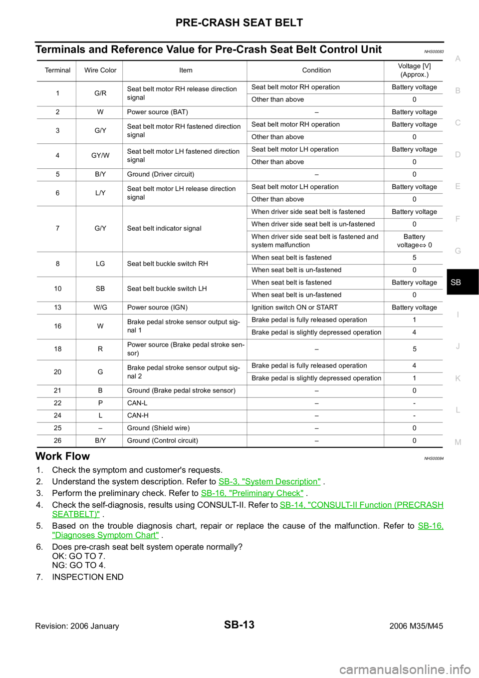
Terminals and Reference Value for Pre-Crash Seat Belt Control UnitNHS00083
Work FlowNHS00084
1. Check the symptom and customer's requests.
2. Understand the system description. Refer to SB-3, "
System Description" .
3. Perform the preliminary check. Refer to SB-16, "
Preliminary Check" .
4. Check the self-diagnosis, results using CONSULT-II. Refer to SB-14, "
CONSULT-II Function (PRECRASH
SEATBELT)" .
5. Based on the trouble diagnosis chart, repair or replace the cause of the malfunction. Refer to SB-16,
"Diagnoses Symptom Chart" .
6. Does pre-crash seat belt system operate normally?
OK: GO TO 7.
NG: GO TO 4.
7. INSPECTION END
Terminal Wire Color Item ConditionVoltage [V]
(Approx.)
1G/RSeat belt motor RH release direction
signalSeat belt motor RH operation Battery voltage
Other than above 0
2 W Power source (BAT) – Battery voltage
3G/YSeat belt motor RH fastened direction
signalSeat belt motor RH operation Battery voltage
Other than above 0
4GY/WSeat belt motor LH fastened direction
signalSeat belt motor LH operation Battery voltage
Other than above 0
5 B/Y Ground (Driver circuit) – 0
6L/YSeat belt motor LH release direction
signalSeat belt motor LH operation Battery voltage
Other than above 0
7 G/Y Seat belt indicator signalWhen driver side seat belt is fastened Battery voltage
When driver side seat belt is un-fastened 0
When driver side seat belt is fastened and
system malfunctionBattery
voltage
0
8 LG Seat belt buckle switch RHWhen seat belt is fastened 5
When seat belt is un-fastened 0
10 SB Seat belt buckle switch LHWhen seat belt is fastened Battery voltage
When seat belt is un-fastened 0
13 W/G Power source (IGN) Ignition switch ON or START Battery voltage
16 WBrake pedal stroke sensor output sig-
nal 1Brake pedal is fully released operation 1
Brake pedal is slightly depressed operation 4
18 RPower source (Brake pedal stroke sen-
sor)
–5
20 GBrake pedal stroke sensor output sig-
nal 2Brake pedal is fully released operation 4
Brake pedal is slightly depressed operation 1
21 B Ground (Brake pedal stroke sensor) – 0
22 P CAN-L – -
24 L CAN-H – -
25 – Ground (Shield wire) – 0
26 B/Y Ground (Control circuit) – 0
Page 5114 of 5621

PRE-CRASH SEAT BELT
SB-15
C
D
E
F
G
I
J
K
L
MA
B
SB
Revision: 2006 January2006 M35/M45
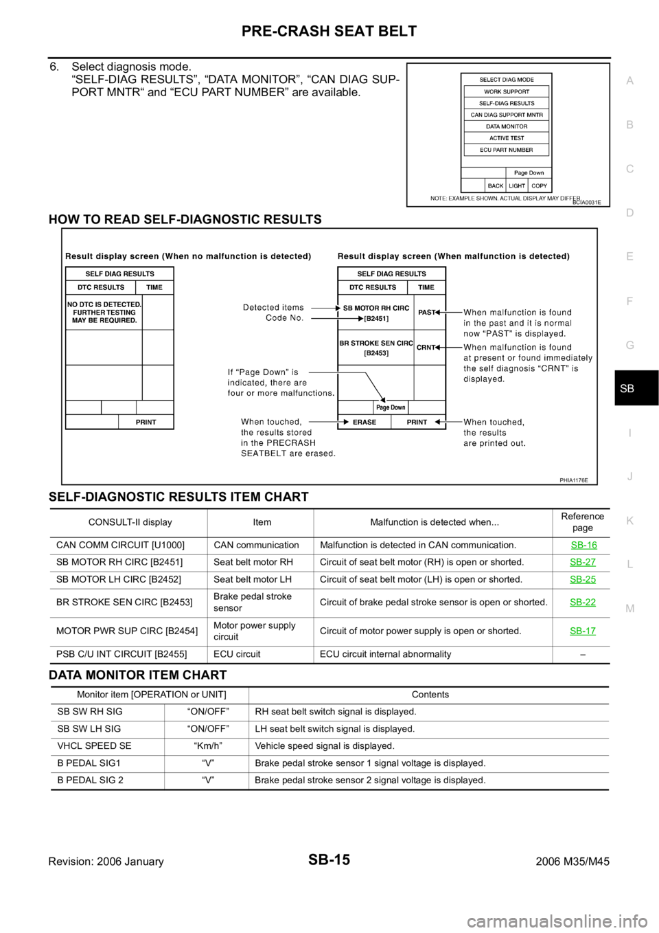
6. Select diagnosis mode.
“SELF-DIAG RESULTS”, “DATA MONITOR”, “CAN DIAG SUP-
PORT MNTR“ and “ECU PART NUMBER” are available.
HOW TO READ SELF-DIAGNOSTIC RESULTS
SELF-DIAGNOSTIC RESULTS ITEM CHART
DATA MONITOR ITEM CHART
BCIA0031E
PHIA1176E
CONSULT-II display Item Malfunction is detected when...Reference
page
CAN COMM CIRCUIT [U1000] CAN communication Malfunction is detected in CAN communication. SB-16
SB MOTOR RH CIRC [B2451] Seat belt motor RH Circuit of seat belt motor (RH) is open or shorted.SB-27
SB MOTOR LH CIRC [B2452] Seat belt motor LH Circuit of seat belt motor (LH) is open or shorted.SB-25
BR STROKE SEN CIRC [B2453]Brake pedal stroke
sensorCircuit of brake pedal stroke sensor is open or shorted.SB-22
MOTOR PWR SUP CIRC [B2454]Motor power supply
circuitCircuit of motor power supply is open or shorted.SB-17
PSB C/U INT CIRCUIT [B2455] ECU circuit ECU circuit internal abnormality –
Monitor item [OPERATION or UNIT] Contents
SB SW RH SIG “ON/OFF” RH seat belt switch signal is displayed.
SB SW LH SIG “ON/OFF” LH seat belt switch signal is displayed.
VHCL SPEED SE “Km/h” Vehicle speed signal is displayed.
B PEDAL SIG1 “V” Brake pedal stroke sensor 1 signal voltage is displayed.
B PEDAL SIG 2 “V” Brake pedal stroke sensor 2 signal voltage is displayed.
Page 5115 of 5621

SB-16
PRE-CRASH SEAT BELT
Revision: 2006 January2006 M35/M45
Preliminary CheckNHS00086
PRE-CRASH SEAT BELT OPERATION INSPECTION
WAR NING :
The following tests should be performed in a safe, open place that is free of traffic and obstacles.
The tests should be performed on a dry, paved road. Do not attempt the tests on wet or unpaved
road, open road, or highway. (This may cause an accident or personal injury.)
Driver and passenger assume it will not operate and prepare themselves accordingly.
1. Tighten driver and passenger seat belts.
2. Drive at approximately 25 km/h (16 MPH).
3. Notify passenger of a sudden stop. Driver and passenger prepare themselves for the possibility of
system not operating. Then, driver fully depresses the brake pedal to stop suddenly.
4. Make sure that the shoulder of the seat belt is pulled while braking.
Diagnoses Symptom ChartNHS00087
Check CAN Communication System Inspection [U1000]NHS00088
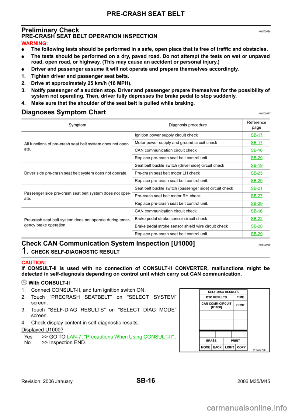
1. CHECK SELF-DIAGNOSTIC RESULT
CAUTION:
If CONSULT-II is used with no connection of CONSULT-II CONVERTER, malfunctions might be
detected in self-diagnosis depending on control unit which carry out CAN communication.
With CONSULT-II
1. Connect CONSULT-II, and turn ignition switch ON.
2. Touch “PRECRASH SEATBELT” on “SELECT SYSTEM”
screen.
3. Touch “SELF-DIAG RESULTS” on “SELECT DIAG MODE”
screen.
4. Check display content in self-diagnostic results.
Displayed U1000?
Yes >> GO TO LAN-7, "Precautions When Using CONSULT-II" .
No >> Inspection END.
Symptom Diagnosis procedureReference
page
All functions of pre-crash seat belt system does not oper-
ate.Ignition power supply circuit checkSB-17
Motor power supply and ground circuit checkSB-17
CAN communication circuit checkSB-16
Replace pre-crash seat belt control unit.SB-29
Driver side pre-crash seat belt system does not operate.Seat belt buckle switch (driver side) circuit checkSB-19Pre-crash seat belt motor LH checkSB-25
Replace pre-crash seat belt control unit.SB-29
Passenger side pre-crash seat belt system does not oper-
ate.Seat belt buckle switch (passenger side) circuit checkSB-21Pre-crash seat belt motor RH checkSB-27
Replace pre-crash seat belt control unit.SB-29
Pre-crash seat belt system does not operate during emer-
gency brake operation.CAN communication circuit checkSB-16Brake pedal stroke sensor circuit checkSB-22
Brake pedal stroke sensor shield wire circuit checkSB-28
Replace pre-crash seat belt control unit.SB-29
PHIA0772E