ECU INFINITI M35 2006 Factory Service Manual
[x] Cancel search | Manufacturer: INFINITI, Model Year: 2006, Model line: M35, Model: INFINITI M35 2006Pages: 5621, PDF Size: 65.56 MB
Page 4825 of 5621
PB-6
PARKING BRAKE SHOE
Revision: 2006 January2006 M35/M45
Removal and InstallationNFS000PV
REMOVAL
WAR NING :
Clean brakes with a vacuum dust collector to minimize the hazard of air borne particles or other mate-
rials.
CAUTION:
Clean dust on disc rotor and back plate using a vacuum dust collector. Do not blow with com-
pressed air.
Put matching marks on both disc rotor and wheel hub when removing disc rotor.
1. Remove rear tires from vehicle with power tool.
2. Remove disc rotor with parking brake pedal completely in the released position. Refer to BR-31,
"Removal and Installation of Brake Caliper Assembly" .
3. If disc rotor cannot be removed, remove as follows:
a. Secure the disc rotor in place with wheel nuts and remove adjuster hole plug.
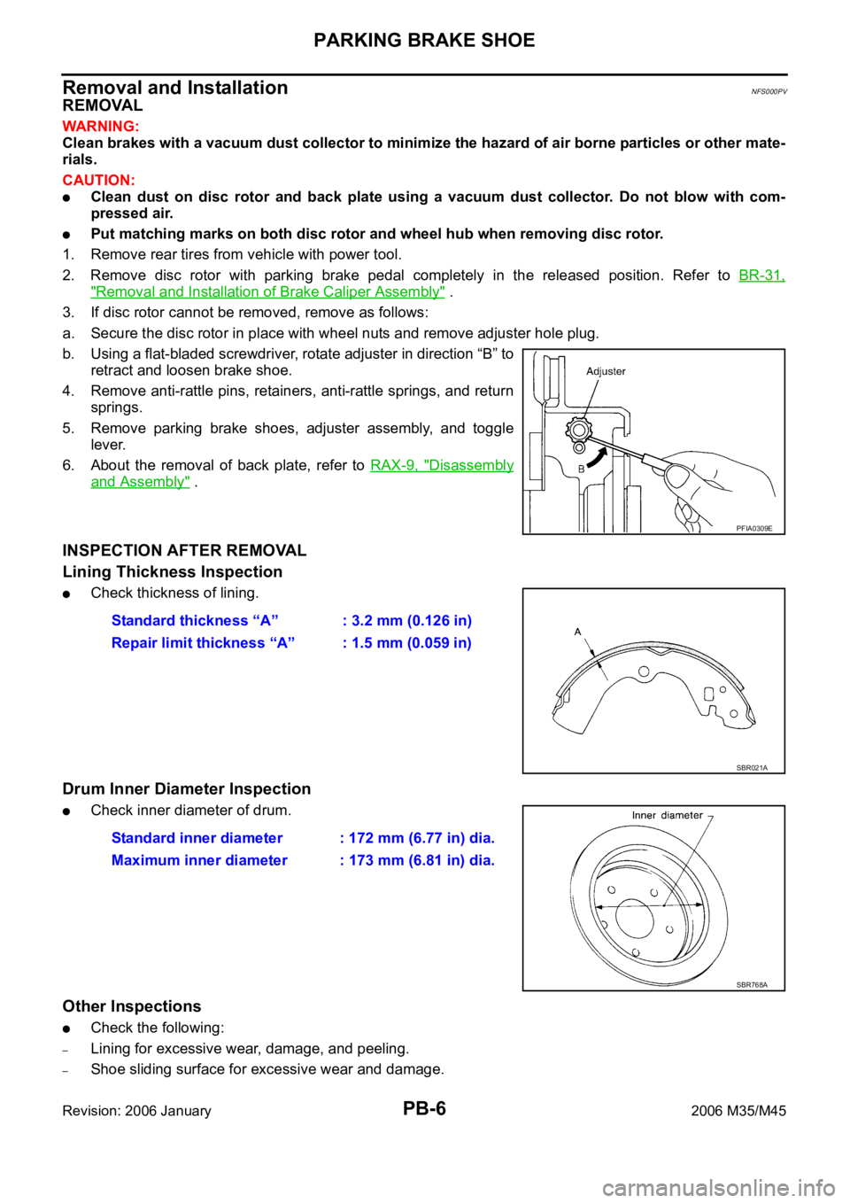
b. Using a flat-bladed screwdriver, rotate adjuster in direction “B” to
retract and loosen brake shoe.
4. Remove anti-rattle pins, retainers, anti-rattle springs, and return
springs.
5. Remove parking brake shoes, adjuster assembly, and toggle
lever.
6. About the removal of back plate, refer to RAX-9, "
Disassembly
and Assembly" .
INSPECTION AFTER REMOVAL
Lining Thickness Inspection
Check thickness of lining.
Drum Inner Diameter Inspection
Check inner diameter of drum.
Other Inspections
Check the following:
–Lining for excessive wear, damage, and peeling.
–Shoe sliding surface for excessive wear and damage.
PFIA0309E
Standard thickness “A” : 3.2 mm (0.126 in)
Repair limit thickness “A” : 1.5 mm (0.059 in)
SBR021A
Standard inner diameter : 172 mm (6.77 in) dia.
Maximum inner diameter : 173 mm (6.81 in) dia.
SBR768A
Page 4860 of 5621
PDU (POWER DISTRIBUTION UNIT)
PG-33
C
D
E
F
G
H
I
J
L
MA
B
PG
Revision: 2006 January2006 M35/M45
PDU (POWER DISTRIBUTION UNIT)PFP:285F1
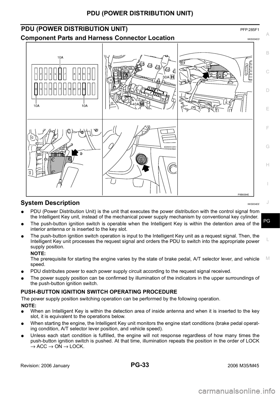
Component Parts and Harness Connector LocationNKS004ED
System DescriptionNKS004EE
PDU (Power Distribution Unit) is the unit that executes the power distribution with the control signal from
the Intelligent Key unit, instead of the mechanical power supply mechanism by conventional key cylinder.
The push-button ignition switch is operable when the Intelligent Key is within the detention area of the
interior antenna or is inserted to the key slot.
The push-button ignition switch operation is input to the Intelligent Key unit as a request signal. Then, the
Intelligent Key unit processes the request signal and orders the PDU to switch into the appropriate power
supply position.
NOTE:
The prerequisite for starting the engine varies by the state of brake pedal, A/T selector lever, and vehicle
speed.
PDU distributes power to each power supply circuit according to the request signal received.
The power supply position can be confirmed by illumination of the indicators in the upper surroundings of
the push-button ignition switch.
PUSH-BUTTON IGNITION SWITCH OPERATING PROCEDURE
The power supply position switching operation can be performed by the following operation.
NOTE:
When an Intelligent Key is within the detection area of inside antenna and when it is inserted to the key
slot, it is equivalent to the operations below.
When starting the engine, the Intelligent Key unit monitors the engine start conditions (brake pedal operat-
ing condition, A/T selector lever position, and vehicle speed).
Unless each start condition is fulfilled, the engine will not response regardless of how many times the
push-button ignition switch is pushed. At that time, illumination repeats the position in the order of LOCK
ACC ON LOCK.
PIIB6094E
Page 4922 of 5621

HARNESS
PG-95
C
D
E
F
G
H
I
J
L
MA
B
PG
Revision: 2006 January2006 M35/M45
PGC/V EC EVAP Canister Purge Volume Control Solenoid Valve
PHASE EC Camshaft Position Sensor (PHASE)
PHSB1 EC Camshaft Position Sensor (PHASE) (Bank 1)
PHSB2 EC Camshaft Position Sensor (PHASE) (Bank 2)
PNP/SW AT Park/Neutral Position Switch
PNP/SW EC Park/Neutral Position Switch
POS EC Crankshaft Position Sensor (CKPS) (POS)
POWER PG Power Supply Routing Circuit
PRE/SE EC EVAP Control System Pressure Sensor
PS/SEN EC Power Steering Pressure Sensor
PSB SB Pre-Crash Seat Belt
R/SEAT SE Auto Return Seat
RAS STC Rear Active Steer
ROOM/L LT Interior Room Lamp
RP/SEN EC Refrigerant Pressure Sensor
SEAT SE Power Seat
SEN/PW EC Sensor Power Supply
SHADE EI Rear Sunshade
SHIFT AT A/T Shift Lock System
SNOWSW EC Snow Mode Switch
SROOF RF Sunroof
SRS SRS Supplemental Restraint System
START SC Starting System
STOP/L LT Stop Lamp
STSIG AT Start Signal Circuit
T/WARN WT Low Tire Pressure Warning System
TAIL/L LT Parking, License and Tail Lamps
TLID BL Trunk Lid Opener
TPS1 EC Throttle Position Sensor (Sensor 1)
TPS2 EC Throttle Position Sensor (Sensor 2)
TPS3 EC Throttle Position Sensor
TRNSCV BL Homelink Universal Transceiver
TURN LT Turn Signal and Hazard Warning Lamp
VDC BRC Vehicle Dynamics Control System
VEHSEC BL Vehicle Security System
VENT/V EC EVAP Canister Vent Control Valve
VIAS EC Variable Induction Air Control System
VIAS/V EC VIAS Control Solenoid Valve
VSSA/T AT Vehicle speed Sensor A/T (Revolution Sensor)
WARN DI Warning Lamps
WINDOW GW Power Window
WIPER WW Front Wiper and Washer Code Section Wiring Diagram Name
Page 4971 of 5621
PS-18
POWER STEERING GEAR
Revision: 2006 January2006 M35/M45
POWER STEERING GEARPFP:49001
Removal and InstallationNGS000DC
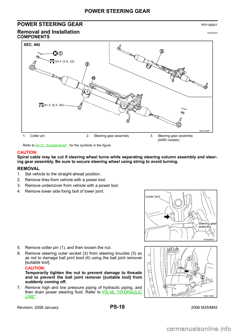
COMPONENTS
CAUTION:
Spiral cable may be cut if steering wheel turns while separating steering column assembly and steer-
ing gear assembly. Be sure to secure steering wheel using string to avoid turning.
REMOVAL
1. Set vehicle to the straight-ahead position.
2. Remove tires from vehicle with a power tool.
3. Remove undercover from vehicle with a power tool.
4. Remove lower side fixing bolt of lower joint.
5. Remove cotter pin (1), and then loosen the nut.
6. Remove steering outer socket (2) from steering knuckle (3) so
as not to damage ball joint boot (4) using the ball joint remover
[suitable tool].
CAUTION:
Temporarily tighten the nut to prevent damage to threads
and to prevent the ball joint remover [suitable tool] from
suddenly coming off.
7. Remove high and low pressure piping of hydraulic piping, and
then drain power steering fluid. Refer to PS-38, "
HYDRAULIC
LINE" .
1. Cotter pin 2. Steering gear assembly 3. Steering gear assembly
(AWD models)
Refer to GI-11, "
Components" , for the symbols in the figure.
SGIA1387E
SGIA0844E
SGIA1183E
Page 4973 of 5621
PS-20
POWER STEERING GEAR
Revision: 2006 January2006 M35/M45
Disassembly and AssemblyNGS000DD
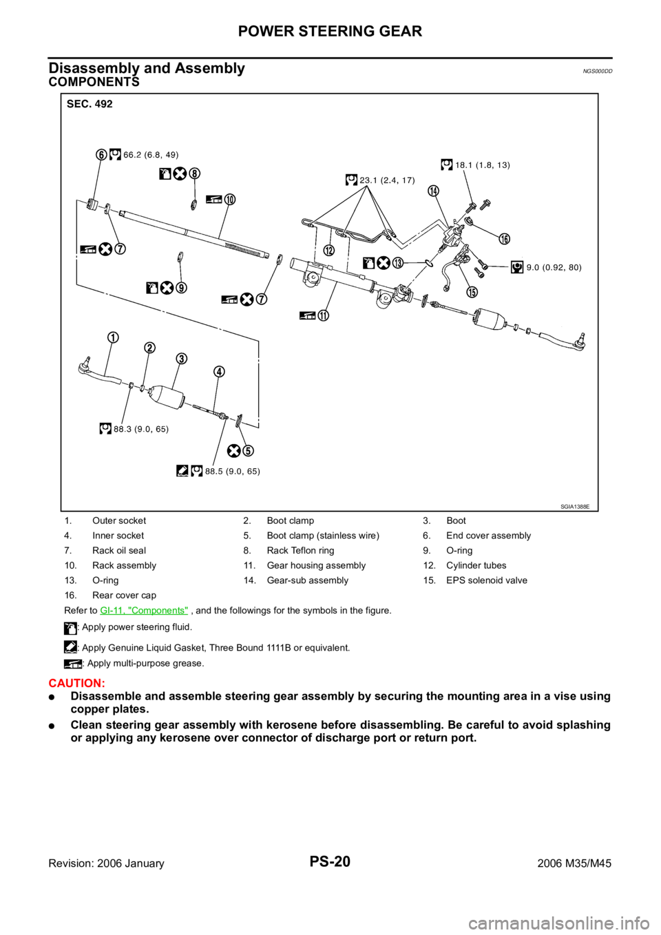
COMPONENTS
CAUTION:
Disassemble and assemble steering gear assembly by securing the mounting area in a vise using
copper plates.
Clean steering gear assembly with kerosene before disassembling. Be careful to avoid splashing
or applying any kerosene over connector of discharge port or return port.
1. Outer socket 2. Boot clamp 3. Boot
4. Inner socket 5. Boot clamp (stainless wire) 6. End cover assembly
7. Rack oil seal 8. Rack Teflon ring 9. O-ring
10. Rack assembly 11. Gear housing assembly 12. Cylinder tubes
13. O-ring 14. Gear-sub assembly 15. EPS solenoid valve
16. Rear cover cap
Refer to GI-11, "
Components" , and the followings for the symbols in the figure.
: Apply power steering fluid.
: Apply Genuine Liquid Gasket, Three Bound 1111 B o r equivalent.
: Apply multi-purpose grease.
SGIA1388E
Page 4984 of 5621

POWER STEERING OIL PUMP
PS-31
C
D
E
F
H
I
J
K
L
MA
B
PS
Revision: 2006 January2006 M35/M45
DISASSEMBLY
NOTE:
Secure oil pump in a vise if necessary.
CAUTION:
Use copper plates when securing in a vise.
1. Remove rear cover mounting bolts, and then remove rear cover from body assembly.
2. Remove gasket from body assembly.
3. Remove dowel pin, cartridge and side plate from body assembly.
4. Remove pulley mounting nut and washer, then remove pulley from drive shaft.
5. Remove snap ring from drive shaft and press out it.
CAUTION:
When removing snap ring, be careful not to damage drive
shaft.
6. Remove oil seal from body assembly using a flat-bladed screw-
driver.
7. Remove O-ring from body assembly.
8. Remove lock nut, and then remove copper washer, joint and O-
ring.
9. Remove connector bolt, and then remove O-ring, flow control
valve and spring from body assembly
10. Remove mounting bolts of suction pipe, and then remove suc-
tion pipe from body assembly.
11. Remove O-ring from body assembly.
INSPECTION AFTER DISASSEMBLY
Body Assembly and Rear Cover Inspection
Check body assembly and rear cover for internal damage. Replace rear cover if it is damaged. Replace oil
pump assembly if body assembly is damaged.
Cartridge Assembly Inspection
Check cam ring, rotor and vane for damage. Replace cartridge assembly if there are.
Side Plate Inspection
Check side plate for damage. Replace side plate if there are.
Flow Control Valve Inspection
Check flow control valve and spring for damage. Replace if there are.
SST010B
SST034A
Page 4985 of 5621

PS-32
POWER STEERING OIL PUMP
Revision: 2006 January2006 M35/M45
ASSEMBLY
NOTE:
Secure oil pump in a vise if necessary.
CAUTION:
Use copper plates when securing in a vise.
1. Apply multi purpose grease to oil seal lips (1). Apply power
steering fluid around oil seal, and then install oil seal to body
assembly.
2. Apply power steering fluid to drive shaft, and press drive shaft
into body assembly, then install snap ring.
3. Apply power steering fluid to O-ring, and install O-ring into body
assembly.
4. Install side plate to body assembly.
5. Install dowel pin (3) into dowel pin hole (A), and install cam ring
(2) pointing it's D
1 side toward the body assembly (1) side as
shown in the figure.
When installing cam ring, turn carved face with a letter E (B)
of it to rear cover.
CAUTION:
Do not confuse the assembling direction of cam ring. If
cam ring is installed facing the incorrect direction, it may
cause oil pump operation malfunction.
6. Install rotor to body assembly.
SGIA1150E
SGIA0422E
SGIA1166E
Page 4988 of 5621

POWER STEERING OIL PUMP
PS-35
C
D
E
F
H
I
J
K
L
MA
B
PS
Revision: 2006 January2006 M35/M45
DISASSEMBLY
NOTE:
Secure oil pump in a vise if necessary.
CAUTION:
Use copper plates when securing in a vise.
1. Remove rear cover mounting bolts, and then remove rear cover from body assembly.
2. Remove O-ring from body assembly.
3. Remove rear side plate from cartridge, and then remove Teflon ring and O-ring from rear side plate.
4. Remove rotor snap ring using a snap ring plier, and remove pul-
ley from body assembly.
CAUTION:
Remove pulley so as not to be damaged when removing
rotor snap ring.
5. Remove cartridge, front side plate, flow control valve A, flow
control valve spring and flow control valve B assembly from
body assembly.
CAUTION:
Do not drop and damage flow control valve A and flow con-
trol valve B assembly when removing.
6. Remove oil seal from body assembly.
7. Remove suction pipe from body assembly.
8. Remove O-ring from body assembly.
9. Remove bracket mounting bolts, and then remove bracket from
body assembly.
INSPECTION AFTER DISASSEMBLY
Body Assembly and Rear Cover Inspection
Check body assembly and rear cover for internal damage. Replace rear cover if it is damaged. Replace oil
pump assembly if body assembly is damaged.
Cartridge Assembly Inspection
Check cam ring, rotor and vane for damage. Replace cartridge assembly if there are.
Side Plate Inspection
Check side plates (front and rear) for damage. Side plates (front and rear) must be replaced as a set if they
are damaged.
Flow Control Valve Inspection
Check flow control valve A, flow control valve spring and flow control valve B assembly for damage. Replace if
there are.
SGIA0059E
SGIA0526E
Page 4989 of 5621

PS-36
POWER STEERING OIL PUMP
Revision: 2006 January2006 M35/M45
ASSEMBLY
NOTE:
Secure oil pump in a vise if necessary.
CAUTION:
Use copper plates when securing in a vise.
1. Apply multi purpose grease to oil seal lips. Apply power steering
fluid to around oil seal, and then install oil seal to body assembly
using the drift [SST].
2. Install bracket to body assembly, and then tighten mounting
bolts to the specified torque.
3. If dowel pin has been removed, insert it into body assembly by
hand. If cannot be inserted by hand, lightly tap with a hammer.
4. Install flow control valve A, flow control valve spring and flow
control valve B assembly as shown in the figure.
5. Install front side plate (3) with dowel pin (2) on flow control valve
A (1) side as shown in the figure aligning with front side plate
cutout (A) to body assembly (4).
6. Install cam ring as shown in the figure.
7. Install pulley to body assembly.
CAUTION:
Do not damage oil seal when installing pulley.
SGIA0527E
SGIA0526E
SGIA1189E
SGIA0612E
Page 4991 of 5621
PS-38
HYDRAULIC LINE
Revision: 2006 January2006 M35/M45
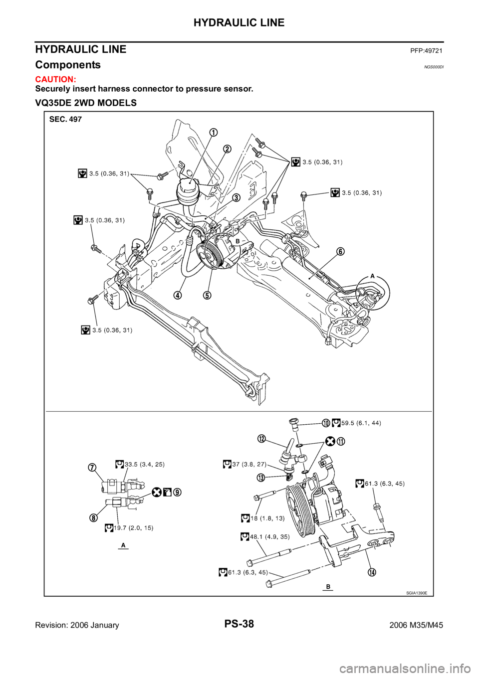
HYDRAULIC LINEPFP:49721
ComponentsNGS000DI
CAUTION:
Securely insert harness connector to pressure sensor.
VQ35DE 2WD MODELS
SGIA1390E