ECU INFINITI M35 2006 Factory Service Manual
[x] Cancel search | Manufacturer: INFINITI, Model Year: 2006, Model line: M35, Model: INFINITI M35 2006Pages: 5621, PDF Size: 65.56 MB
Page 5189 of 5621

SE-8
SQUEAK AND RATTLE TROUBLE DIAGNOSES
Revision: 2006 January2006 M35/M45
TRUNK
Trunk noises are often caused by a loose jack or loose items put into the trunk by the owner.
In addition look for:
1. Trunk lid dumpers out of adjustment
2. Trunk lid striker out of adjustment
3. The trunk lid torsion bars knocking together
4. A loose license plate or bracket
Most of these incidents can be repaired by adjusting, securing or insulating the item(s) or component(s) caus-
ing the noise.
SUNROOF/HEADLINING
Noises in the sunroof/headlining area can often be traced to one of the following:
1. Sunroof lid, rail, linkage or seals making a rattle or light knocking noise
2. Sunvisor shaft shaking in the holder
3. Front or rear windshield touching headlining and squeaking
Again, pressing on the components to stop the noise while duplicating the conditions can isolate most of these
incidents. Repairs usually consist of insulating with felt cloth tape.
SEATS
When isolating seat noise it's important to note the position the seat is in and the load placed on the seat when
the noise is present. These conditions should be duplicated when verifying and isolating the cause of the
noise.
Cause of seat noise include:
1. Headrest rods and holder
2. A squeak between the seat pad cushion and frame
3. The rear seatback lock and bracket
These noises can be isolated by moving or pressing on the suspected components while duplicating the con-
ditions under which the noise occurs. Most of these incidents can be repaired by repositioning the component
or applying urethane tape to the contact area.
UNDERHOOD
Some interior noise may be caused by components under the hood or on the engine wall. The noise is then
transmitted into the passenger compartment.
Causes of transmitted underhood noise include:
1. Any component mounted to the engine wall
2. Components that pass through the engine wall
3. Engine wall mounts and connectors
4. Loose radiator mounting pins
5. Hood bumpers out of adjustment
6. Hood striker out of adjustment
These noises can be difficult to isolate since they cannot be reached from the interior of the vehicle. The best
method is to secure, move or insulate one component at a time and test drive the vehicle. Also, engine RPM
or load can be changed to isolate the noise. Repairs can usually be made by moving, adjusting, securing, or
insulating the component causing the noise.
Page 5216 of 5621
AUTOMATIC DRIVE POSITIONER
SE-35
C
D
E
F
G
H
J
K
L
MA
B
SE
Revision: 2006 January2006 M35/M45
CONSULT-II Function (AUTO DRIVE POS.)NIS00260
CONSULT-II can display each diagnostic item using the diagnostic test modes shown following.
CONSULT-II INSPECTION PROCEDURE
CAUTION:
If CONSULT-II is used with no connection of CONSULT-II CONVERTER, malfunctions might be
detected in self-diagnosis depending on control unit which carry out CAN communication.
1. Turn ignition switch “OFF”.
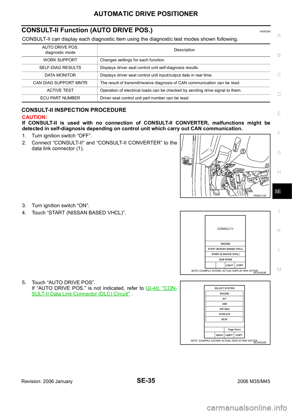
2. Connect “CONSULT-II” and “CONSULT-II CONVERTER” to the
data link connector (1).
3. Turn ignition switch “ON”.
4. Touch “START (NISSAN BASED VHCL)”.
5. Touch “AUTO DRIVE POS”.
If “AUTO DRIVE POS.” is not indicated, refer to GI-40, "
CON-
SULT-II Data Link Connector (DLC) Circuit" .
AUTO DRIVE POS.
diagnostic modeDescription
WORK SUPPORT Changes settings for each function.
SELF-DIAG RESULTS Displays driver seat control unit self-diagnosis results.
DATA MONITOR Displays driver seat control unit input/output data in real time.
CAN DIAG SUPPORT MNTR The result of transmit/receive diagnosis of CAN communication can be read.
ACTIVE TEST Operation of electrical loads can be checked by sending drive signal to them.
ECU PART NUMBER Driver seat control unit part number can be read.
PBIB2712E
BCIA0029E
BCIA0030E
Page 5217 of 5621

SE-36
AUTOMATIC DRIVE POSITIONER
Revision: 2006 January2006 M35/M45
6. Select diagnosis mode.
“DATA MONITOR”, “ACTIVE TEST”, “SELF-DIAG RESULTS“,
“ECU PART NUMBER”, “CAN DIAG SUPPORT MNTR” and
“WORK SUPPORT” are available.
SELF-DIAGNOSIS RESULTS
HOW TO READ SELF-DIAG RESULTS
NOTE:
CAN communication malfunction and detention switch malfunction are displayed on “TIME”. (1)
–If error is detected in the present, “CRNT” is displayed.
–If error is detected in the past (present error is not detected), “PAST” is displayed.
–If error has never been detected, nothing is displayed on “TIME”.
Any items other than CAN communication malfunction and detention switch malfunction are counted. (2)
–If error is detected, error detection frequency is displayed from “1” to “127” on “TIME”.
–If error has never been detected, nothing is displayed on “TIME”.
–Can clear the detected memory.
Normal: Clear memory in normal condition, history is erased and nothing is displayed on “TIME”.
Error: Clear memory in error condition, error is detected again and “1” is displayed on “TIME”.
DISPLAY ITEM LIST
BCIA0031E
CONSULT-II display Item Malfunction is detected when...Reference
page
CAN COMM CIRC
[U1000]CAN communication Malfunction is detected in CAN communication.SE-41
SEAT SLIDE
[B2112]Seat slide motorWhen any manual and automatic operations are not performed, if
any motor operations of seat slide is detected for 0.1 second or
more, status is judged “Output error”.SE-44
SE-52
SEAT RECLINING
[B2113]Seat reclining motorWhen any manual and automatic operations are not performed, if
any motor operations of seat reclining is detected for 0.1 second or
more, status is judged “Output error”.SE-45
SE-54
PIIB6449E
Page 5348 of 5621
FRONT SEAT
SE-167
C
D
E
F
G
H
J
K
L
MA
B
SE
Revision: 2006 January2006 M35/M45
Removal and InstallationNIS0028G
CAUTION:
When removing and installing, use shop cloths to protect parts from damage.
REMOVAL
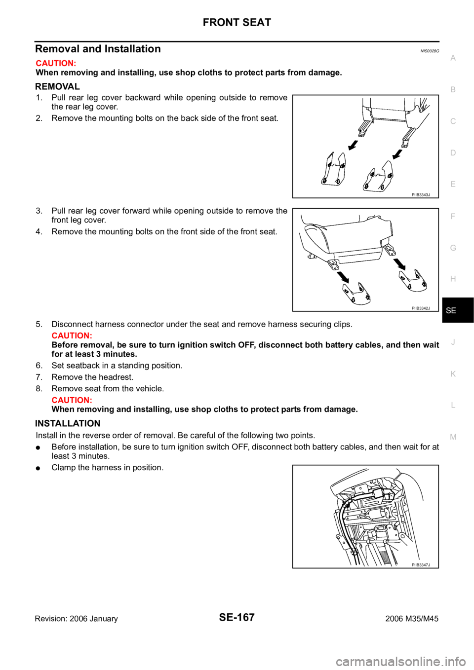
1. Pull rear leg cover backward while opening outside to remove
the rear leg cover.
2. Remove the mounting bolts on the back side of the front seat.
3. Pull rear leg cover forward while opening outside to remove the
front leg cover.
4. Remove the mounting bolts on the front side of the front seat.
5. Disconnect harness connector under the seat and remove harness securing clips.
CAUTION:
Before removal, be sure to turn ignition switch OFF, disconnect both battery cables, and then wait
for at least 3 minutes.
6. Set seatback in a standing position.
7. Remove the headrest.
8. Remove seat from the vehicle.
CAUTION:
When removing and installing, use shop cloths to protect parts from damage.
INSTALLATION
Install in the reverse order of removal. Be careful of the following two points.
Before installation, be sure to turn ignition switch OFF, disconnect both battery cables, and then wait for at
least 3 minutes.
Clamp the harness in position.
PIIB3343J
PIIB3342J
PIIB3347J
Page 5350 of 5621

FRONT SEAT
SE-169
C
D
E
F
G
H
J
K
L
MA
B
SE
Revision: 2006 January2006 M35/M45
Remove the bracket mounting nuts.
Remove seatback trim and pad from seatback frame.
Remove the hog rings to separate the trim and pad.
2. Remove seatback frame.
Remove seat speaker. (Applied 5.1 ch BOSE studio surround® system models) Refer to AV-287, "Seat
Speaker" .
Remove the bands, and then remove seatback thermal electrical device (TED) assembly.
Remove the seat harness assembly from seatback assembly.
Remove the bolts, and then remove seatback frame from seat cushion frame.
Assembly
Assemble in the reverse order of disassembly. Be careful of the following one point.
Install the hog rings of seat cushion trim in position, and then
securely connect the trim or trim code with the pad side wire.
SEAT CUSHION
Disassembly
1. Remove the seatback trim and seatback pad.
Remove the retainer from the lower side of seatback board.
Disconnect the clip and pawl, and then remove seatback
board.
: Pawl
: Clip
Remove the screws and disconnect the clips, and then
remove the seat cushion rear finisher. (Climate controlled
seat model)
PIIB3356J
PIIB3344J
PIIB3345J
Page 5352 of 5621

FRONT SEAT
SE-171
C
D
E
F
G
H
J
K
L
MA
B
SE
Revision: 2006 January2006 M35/M45
Remove driver's seat control unit. (Driver's seat only)
Remove the driver seat control switch.
Remove seat cushion finisher B and seat cushion finisher C.
Remove seat harnesses.
Assembly
Assemble in the reverse order of disassembly. Be careful of the following two points.
Install the hog rings of seat cushion trim in position, and then
securely connect the trim or trim code with the pad side wire.
Clamp the harness in position.
CLIMATE CONTROLLED SEAT
Blower Filter Replacement
Put your hand behind front seat cushion, pull filter downward and
remove it. Replace filter with a new one.
NOTE:
When replacing, be sure to set the front seat lifter to the top
position.
When installing, do not confuse up-down direction of the filter.
PIIB3357J
PIIB3356J
PIIB6502E
Page 5357 of 5621
SE-176
REAR SEAT
Revision: 2006 January2006 M35/M45
Removal and InstallationNIS0028K
CAUTION:
When removing and installing, use shop cloths to protect parts from damage.
BENCH SEAT
Removal
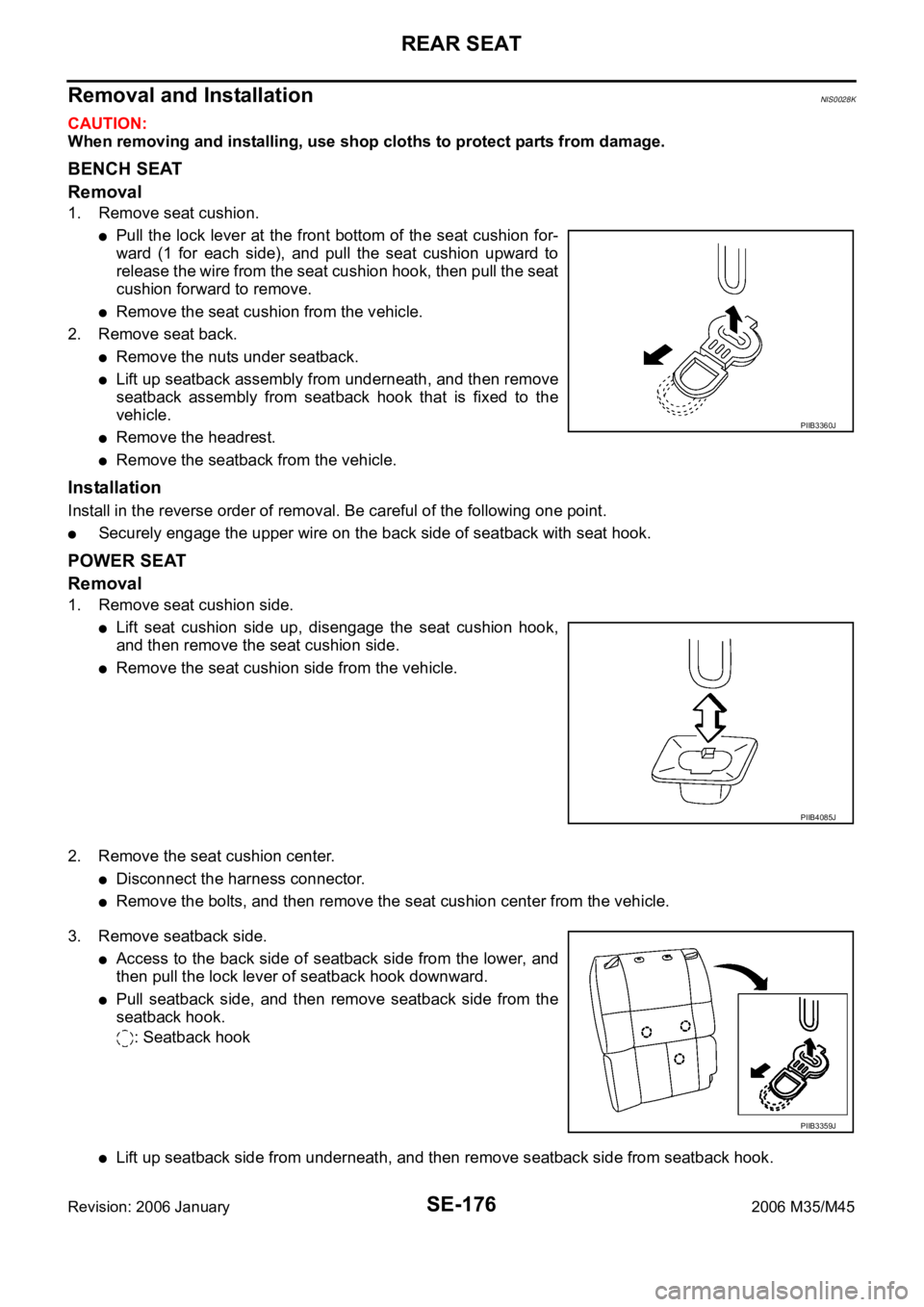
1. Remove seat cushion.
Pull the lock lever at the front bottom of the seat cushion for-
ward (1 for each side), and pull the seat cushion upward to
release the wire from the seat cushion hook, then pull the seat
cushion forward to remove.
Remove the seat cushion from the vehicle.
2. Remove seat back.
Remove the nuts under seatback.
Lift up seatback assembly from underneath, and then remove
seatback assembly from seatback hook that is fixed to the
vehicle.
Remove the headrest.
Remove the seatback from the vehicle.
Installation
Install in the reverse order of removal. Be careful of the following one point.
Securely engage the upper wire on the back side of seatback with seat hook.
POWER SEAT
Removal
1. Remove seat cushion side.
Lift seat cushion side up, disengage the seat cushion hook,
and then remove the seat cushion side.
Remove the seat cushion side from the vehicle.
2. Remove the seat cushion center.
Disconnect the harness connector.
Remove the bolts, and then remove the seat cushion center from the vehicle.
3. Remove seatback side.
Access to the back side of seatback side from the lower, and
then pull the lock lever of seatback hook downward.
Pull seatback side, and then remove seatback side from the
seatback hook.
: Seatback hook
Lift up seatback side from underneath, and then remove seatback side from seatback hook.
PIIB3360J
PIIB4085J
PIIB3359J
Page 5358 of 5621
REAR SEAT
SE-177
C
D
E
F
G
H
J
K
L
MA
B
SE
Revision: 2006 January2006 M35/M45
Disconnect the harness connector.
Remove the headrest.
Remove the seatback side from the vehicle.
4. Remove seatback center.
Disconnect the harness connector.
Remove the seatback center mounting bolts and nuts.
Remove the seatback center from the vehicle.
5. Remove the rear seat frame.
Disconnect the harness connector.
Remove the bolts and nuts, and then remove the rear seat frame.
Installation
Install in the reverse order of removal.
Disassembly and AssemblyNIS0028L
BENCH SEAT
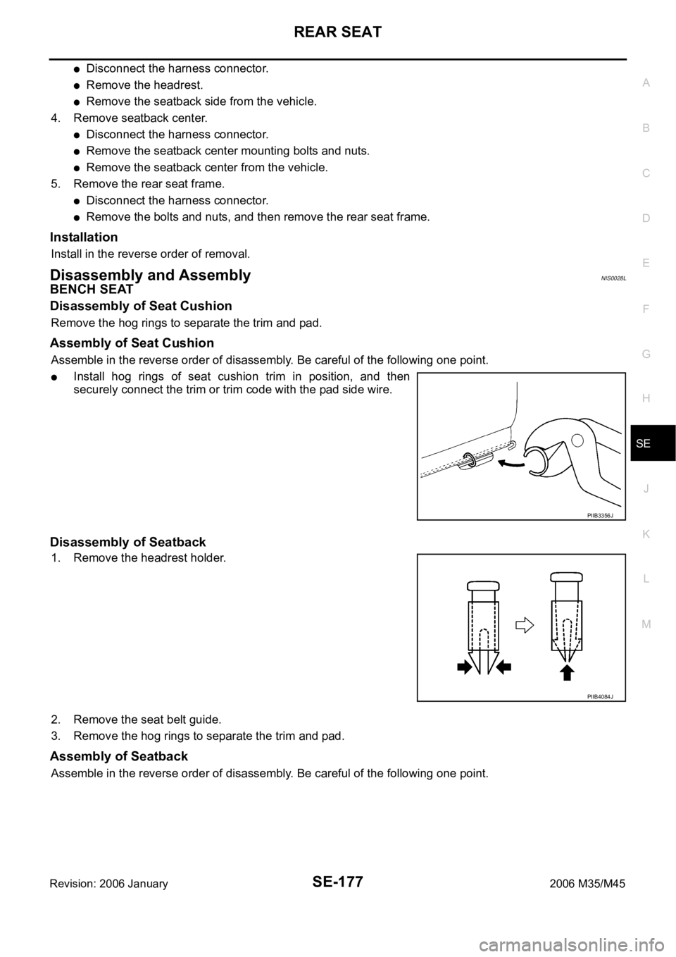
Disassembly of Seat Cushion
Remove the hog rings to separate the trim and pad.
Assembly of Seat Cushion
Assemble in the reverse order of disassembly. Be careful of the following one point.
Install hog rings of seat cushion trim in position, and then
securely connect the trim or trim code with the pad side wire.
Disassembly of Seatback
1. Remove the headrest holder.
2. Remove the seat belt guide.
3. Remove the hog rings to separate the trim and pad.
Assembly of Seatback
Assemble in the reverse order of disassembly. Be careful of the following one point.
PIIB3356J
PIIB4084J
Page 5359 of 5621
SE-178
REAR SEAT
Revision: 2006 January2006 M35/M45
Install hog rings of seat cushion trim in position, and then
securely connect the trim or trim code with the pad side wire.
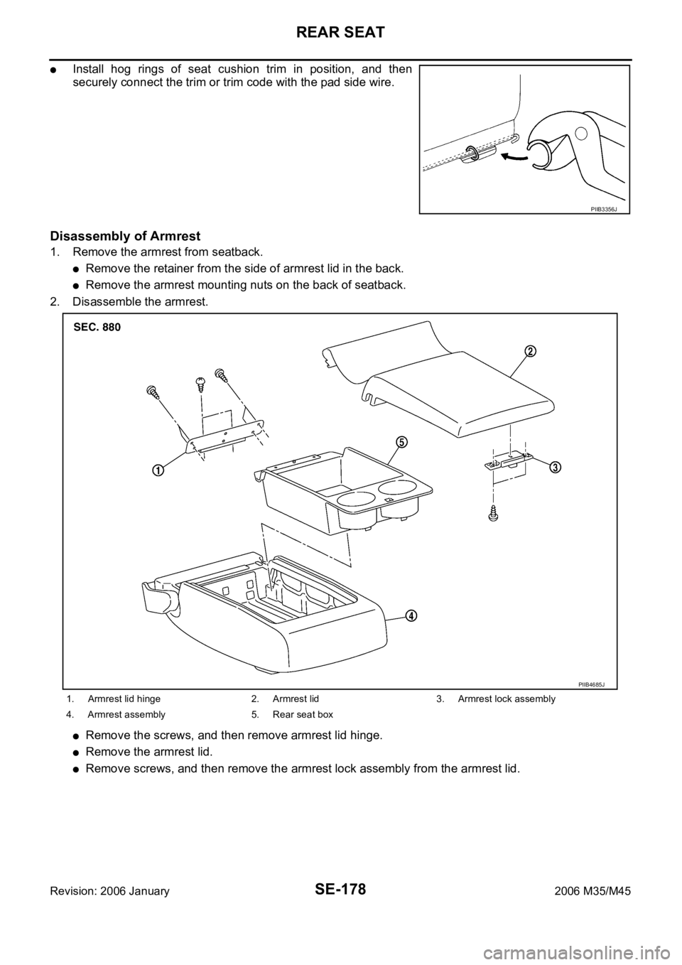
Disassembly of Armrest
1. Remove the armrest from seatback.
Remove the retainer from the side of armrest lid in the back.
Remove the armrest mounting nuts on the back of seatback.
2. Disassemble the armrest.
Remove the screws, and then remove armrest lid hinge.
Remove the armrest lid.
Remove screws, and then remove the armrest lock assembly from the armrest lid.
PIIB3356J
1. Armrest lid hinge 2. Armrest lid 3. Armrest lock assembly
4. Armrest assembly 5. Rear seat box
PIIB4685J
Page 5360 of 5621

REAR SEAT
SE-179
C
D
E
F
G
H
J
K
L
MA
B
SE
Revision: 2006 January2006 M35/M45
Pull the rear seat box rearward and lift up, and then remove
rear seat box from the armrest assembly.
CAUTION:
When removing, check that front tab is not damaged.
If the tab is damaged when removing the rear seat box,
replace rear seat box with a new one.
Assembly of Armrest
Assemble in the reverse order of disassembly.
POWER SEAT
Disassembly of Seat Cushion
Remove the hog rings to separate the trim and pad.
Assembly of Seat Cushion
Assemble in the reverse order of disassembly.
Disassembly of Seatback
1. Remove the headrest holder.
2. Remove the seat belt guide.
3. Remove the hog rings to separate the trim and pad.
Assembly of Seatback
Assemble in the reverse order of disassembly. Be careful of the following one point.
Install hog rings of seat cushion trim in position, and then
securely connect the trim or trim code with the pad side wire.
Disassembly of Seat Frame
1. Disconnect the harness connectors, remove the screws,and then remove the rear seat control unit.
2. Remove the seatback hook and seat cushion hook.
Assembly of Seat Frame
Assemble in the reverse order of removal.
Disassembly of Armrest
1. Remove the armrest from seatback center.
Remove the retainer from the side of armrest lid in the back.
Remove the armrest mounting nuts on the back of seatback.
PIIB4686J
PIIB4084J
PIIB3356J